User Manual
Page 2
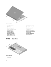
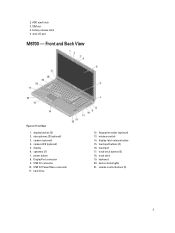
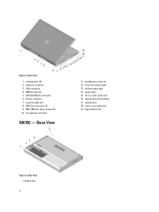
VGA connector 3. headphone connector 12. ExpressCard slot Figure 3. battery bay 2 eSATA/USB 2.0 connector 5. security cable slot 8. Base View 11. hard-drive status light 13. Base View 1. cooling vents (2) 2. power light 15. 10-in-1 card reader slot 16. USB 2.0 connectors (2) 9. microphone connector M4700 - optical drive 18. network connector 4. power connector 7. battery status light 14. optical-drive eject button 17. HDMI connector 6. Figure 2. Back View 1. smart card reader slot 19. IEEE 1394 port (4-pin) 10.
VGA connector 3. headphone connector 12. ExpressCard slot Figure 3. battery bay 2 eSATA/USB 2.0 connector 5. security cable slot 8. Base View 11. hard-drive status light 13. Base View 1. cooling vents (2) 2. power light 15. 10-in-1 card reader slot 16. USB 2.0 connectors (2) 9. microphone connector M4700 - optical drive 18. network connector 4. power connector 7. battery status light 14. optical-drive eject button 17. HDMI connector 6. Figure 2. Back View 1. smart card reader slot 19. IEEE 1394 port (4-pin) 10.
User Manual
Page 3
dock I/O port M6700 - camera (optional) 4. DisplayPort connector 9. touchpad 17. device status lights 21. Front and Back View Figure 4. USB 3.0 PowerShare connector 11. wireless switch 14. HDD eject latch 3. ...
dock I/O port M6700 - camera (optional) 4. DisplayPort connector 9. touchpad 17. device status lights 21. Front and Back View Figure 4. USB 3.0 PowerShare connector 11. wireless switch 14. HDD eject latch 3. ...
User Manual
Page 4
Figure 5. VGA connector 4. security cable slot 8. Base View 11. HDMI connector 5. USB 2.0 connectors (2) 9. power light 15. 10-in-1 card reader slot 16. Base View 1. battery status light 14. smart card reader slot 19. battery bay 4 cooling vents (2) 2. power connector 7. ExpressCard slot Figure 6. eSATA/USB 2.0 connector 6. headphone connector 12. optical-drive eject button 17. network connector 3. microphone connector M6700 - Back View 1. IEEE 1394 port (6-pin, powered) 10. hard-drive status light 13. optical drive 18.
Figure 5. VGA connector 4. security cable slot 8. Base View 11. HDMI connector 5. USB 2.0 connectors (2) 9. power light 15. 10-in-1 card reader slot 16. Base View 1. battery status light 14. smart card reader slot 19. battery bay 4 cooling vents (2) 2. power connector 7. ExpressCard slot Figure 6. eSATA/USB 2.0 connector 6. headphone connector 12. optical-drive eject button 17. network connector 3. microphone connector M6700 - Back View 1. IEEE 1394 port (6-pin, powered) 10. hard-drive status light 13. optical drive 18.
User Manual
Page 5
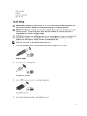
dock I/O port Quick Setup WARNING: Before you follow the angle of the procedures in this section, read the safety information that shipped with electrical outlets worldwide. USB ... 2. Connect IEEE 1394 devices, such as a mouse or keyboard (optional). battery release latch 5. Figure 8. Figure 9. HDD eject latch 3. For additional best practices information, see www.dell.com/regulatory_compliance WARNING: The AC adapter works with your computer. Connect the network cable (optional). Network Connector 3. Connect USB devices, such as a 1394 hard drive...
dock I/O port Quick Setup WARNING: Before you follow the angle of the procedures in this section, read the safety information that shipped with electrical outlets worldwide. USB ... 2. Connect IEEE 1394 devices, such as a mouse or keyboard (optional). battery release latch 5. Figure 8. Figure 9. HDD eject latch 3. For additional best practices information, see www.dell.com/regulatory_compliance WARNING: The AC adapter works with your computer. Connect the network cable (optional). Network Connector 3. Connect USB devices, such as a 1394 hard drive...
Owner's Manual
Page 4
......50 Removing the Hinge Cover...50 Installing the Hinge Cover...51 Removing the System Board...51 Installing the System Board...54 Removing the Power-Connector Port...55 Installing the Power Connector Port...56 Removing the Switch Board...56 Installing the Switch Board...57 3 System Setup...59
......50 Removing the Hinge Cover...50 Installing the Hinge Cover...51 Removing the System Board...51 Installing the System Board...54 Removing the Power-Connector Port...55 Installing the Power Connector Port...56 Removing the Switch Board...56 Installing the Switch Board...57 3 System Setup...59
Owner's Manual
Page 9
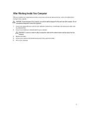
Do not use only the battery designed for other Dell computers. 1. After Working Inside Your Computer After you complete any replacement procedure, ensure you connect any external devices, cards, and cables before turning on your ... cable, first plug the cable into the network device and then plug it into the computer. 3. Replace the battery. 4. Connect any external devices, such as a port replicator, battery slice, or media base, and replace any telephone or network cables to your computer and all attached devices to the computer, use batteries...
Do not use only the battery designed for other Dell computers. 1. After Working Inside Your Computer After you complete any replacement procedure, ensure you connect any external devices, cards, and cables before turning on your ... cable, first plug the cable into the network device and then plug it into the computer. 3. Replace the battery. 4. Connect any external devices, such as a port replicator, battery slice, or media base, and replace any telephone or network cables to your computer and all attached devices to the computer, use batteries...
Owner's Manual
Page 55
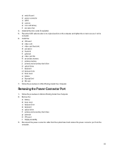
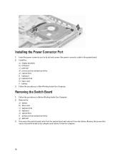
... and tighten the screw to secure it to the computer. 6. Disconnect the power-connector cable from the system board and remove the power connector port from the computer. 55 Place the LVDS cable bracket in After Working Inside Your Computer. Removing the Power-Connector... Port 1. Install the: a) I /O board i) display assembly 3. Follow the procedures in Before Working Inside Your Computer. 2. Install all the mini-cards (if available). 5. Remove the: a) battery b) ...
... and tighten the screw to secure it to the computer. 6. Disconnect the power-connector cable from the system board and remove the power connector port from the computer. 55 Place the LVDS cable bracket in After Working Inside Your Computer. Removing the Power-Connector... Port 1. Install the: a) I /O board i) display assembly 3. Follow the procedures in Before Working Inside Your Computer. 2. Install all the mini-cards (if available). 5. Remove the: a) battery b) ...
Owner's Manual
Page 56
... the latches. Install the: a) display assembly b) I/O board c) palmrest d) primary and secondary hard drive e) optical drive f) keyboard g) keyboard trim h) base cover i) battery 3. Insert the power-connector port in its slot and connect the power-connector cable to the computer and remove it from the computer. 56 Installing the Power Connector...
... the latches. Install the: a) display assembly b) I/O board c) palmrest d) primary and secondary hard drive e) optical drive f) keyboard g) keyboard trim h) base cover i) battery 3. Insert the power-connector port in its slot and connect the power-connector cable to the computer and remove it from the computer. 56 Installing the Power Connector...
Owner's Manual
Page 61
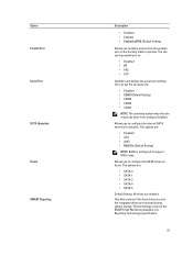
...controls if the hard drive errors for the integrated drives are enabled. You can set the parallel port to configure the SATA drives on the docking station operates. Option Parallel Port Serial Port SATA Operation Drives SMART Reporting Description • Disabled • Enabled • Enabled w/PXE ...(Default Setting) Allows you to configure the internal SATA hard-drive controller. Allows you to define and set the serial port to: • Disabled • COM1 (Default Setting) • COM2 • COM3 • COM4 NOTE: The operating system may allocate ...
...controls if the hard drive errors for the integrated drives are enabled. You can set the parallel port to configure the SATA drives on the docking station operates. Option Parallel Port Serial Port SATA Operation Drives SMART Reporting Description • Disabled • Enabled • Enabled w/PXE ...(Default Setting) Allows you to configure the internal SATA hard-drive controller. Allows you to define and set the serial port to: • Disabled • COM1 (Default Setting) • COM2 • COM3 • COM4 NOTE: The operating system may allocate ...
Owner's Manual
Page 62
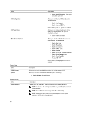
.... • Enable Optimus - The options are: • Enable Fixed Bay • Enable Microphone • Enable ExpressCard • Enable eSATA Ports • Enable Camera • Enable Hard Drive Free Fall Protection • Enable Media Card and 1394 • Enable Media Card Only •...Allows you enable or disable the various on board devices. The options are: • Enable Boot Support • Enable External USB Port Default Setting: both the options are enabled. This option is Off. Default Setting. Option USB Configuration USB PowerShare Miscellaneous Devices Table ...
.... • Enable Optimus - The options are: • Enable Fixed Bay • Enable Microphone • Enable ExpressCard • Enable eSATA Ports • Enable Camera • Enable Hard Drive Free Fall Protection • Enable Media Card and 1394 • Enable Media Card Only •...Allows you enable or disable the various on board devices. The options are: • Enable Boot Support • Enable External USB Port Default Setting: both the options are enabled. This option is Off. Default Setting. Option USB Configuration USB PowerShare Miscellaneous Devices Table ...
Owner's Manual
Page 77
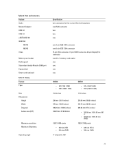
....60 inches) 344.23 mm X 193.54 mm 1920 X 1080 pixels • 220 nits (HD) • 300 nits (FHD) 0° (closed) to 135° M6700 • HD+ (1600 X 900) • FHD (1920 X 1080) 17.3 inches 270.60 mm (10.65 inches) 416.70 mm (16.40 inches) 439.42 mm... +) • 381.89 mm X 214.81 mm (FHD) 1920 X 1080 pixels • 220 nits (HD+) • 300 nits (FHD) 77 Ports and Connectors Feature Audio Network Adapter USB 2.0 USB 3.0 eSATA\USB 2.0 IEEE1394: M4700 M6700 Video Memory card reader Docking port Subscriber Identity Module (SIM) port ExpressCard Smart card (optional) Table 23. Table 22.
....60 inches) 344.23 mm X 193.54 mm 1920 X 1080 pixels • 220 nits (HD) • 300 nits (FHD) 0° (closed) to 135° M6700 • HD+ (1600 X 900) • FHD (1920 X 1080) 17.3 inches 270.60 mm (10.65 inches) 416.70 mm (16.40 inches) 439.42 mm... +) • 381.89 mm X 214.81 mm (FHD) 1920 X 1080 pixels • 220 nits (HD+) • 300 nits (FHD) 77 Ports and Connectors Feature Audio Network Adapter USB 2.0 USB 3.0 eSATA\USB 2.0 IEEE1394: M4700 M6700 Video Memory card reader Docking port Subscriber Identity Module (SIM) port ExpressCard Smart card (optional) Table 23. Table 22.


