User Manual
Page 1
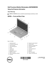
...stick buttons (3) 18. fingerprint reader (optional) 13. wireless switch 14. display latch release button 15. Dell Precision Mobile Workstation M4700/M6700 Setup And Features Information About Warnings WARNING: A WARNING indicates a potential for property damage, personal injury, or... death. Front and Back View Figure 1. Front View 1. USB 3.0 PowerShare connector 11. display 6. speakers (2) 7. track stick 19. display latches (2) 2. keyboard 20...
...stick buttons (3) 18. fingerprint reader (optional) 13. wireless switch 14. display latch release button 15. Dell Precision Mobile Workstation M4700/M6700 Setup And Features Information About Warnings WARNING: A WARNING indicates a potential for property damage, personal injury, or... death. Front and Back View Figure 1. Front View 1. USB 3.0 PowerShare connector 11. display 6. speakers (2) 7. track stick 19. display latches (2) 2. keyboard 20...
User Manual
Page 3
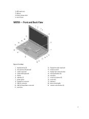
display latches (2) 2. display 6. DisplayPort connector 9. device status lights 21. camera (optional) 4. power button 8. dock I/O port M6700 - USB 3.0 connector 10. hard drive 12. touchpad buttons (3) 16. track-stick buttons (3) 18. touchpad 17. volume control buttons (3) 3 Front and Back View Figure 4. speakers (2) 7. battery ...) 3. display-latch release button 15. wireless switch 14. USB 3.0 PowerShare connector 11. 2. HDD eject latch 3. camera LED (optional) 5. fingerprint reader (optional) 13. track stick 19. keyboard 20.
display latches (2) 2. display 6. DisplayPort connector 9. device status lights 21. camera (optional) 4. power button 8. dock I/O port M6700 - USB 3.0 connector 10. hard drive 12. touchpad buttons (3) 16. track-stick buttons (3) 18. touchpad 17. volume control buttons (3) 3 Front and Back View Figure 4. speakers (2) 7. battery ...) 3. display-latch release button 15. wireless switch 14. USB 3.0 PowerShare connector 11. 2. HDD eject latch 3. camera LED (optional) 5. fingerprint reader (optional) 13. track stick 19. keyboard 20.
User Manual
Page 5
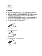
However, power connectors and power strips vary among countries. Connect the network cable (optional). Connect IEEE 1394 devices, such as a mouse or keyboard (optional). battery release latch 5. Using an incompatible cable or improperly connecting the cable to avoid damaging the cable. AC Adapter 2. Figure 8. USB Connector 4. dock ... shipped with electrical outlets worldwide. Connect USB devices, such as a 1394 hard drive (optional). 5 SIM slot 4. For additional best practices information, see www.dell.com/regulatory_compliance WARNING: The AC adapter works with your computer.
However, power connectors and power strips vary among countries. Connect the network cable (optional). Connect IEEE 1394 devices, such as a mouse or keyboard (optional). battery release latch 5. Using an incompatible cable or improperly connecting the cable to avoid damaging the cable. AC Adapter 2. Figure 8. USB Connector 4. dock ... shipped with electrical outlets worldwide. Connect USB devices, such as a 1394 hard drive (optional). 5 SIM slot 4. For additional best practices information, see www.dell.com/regulatory_compliance WARNING: The AC adapter works with your computer.
Statement of Volatility
Page 1
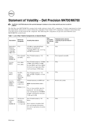
...M6700 CAUTION: A CAUTION indicates either potential damage to hardware or loss of system memory. Table 1. Volatile components lose their data even after power is removed from the component. System memory size will depend on System Board Description Reference Designator Volatility Description User Accessible for keyboard...- 2-4 present Stores memory manufacturer data and timing information for basic boot operation, PSA (on the Dell Precision M4700/M6700 system board. Statement of Volatility - Non-volatile (NV) components continue to four modules must be ...
...M6700 CAUTION: A CAUTION indicates either potential damage to hardware or loss of system memory. Table 1. Volatile components lose their data even after power is removed from the component. System memory size will depend on System Board Description Reference Designator Volatility Description User Accessible for keyboard...- 2-4 present Stores memory manufacturer data and timing information for basic boot operation, PSA (on the Dell Precision M4700/M6700 system board. Statement of Volatility - Non-volatile (NV) components continue to four modules must be ...
Owner's Manual
Page 3
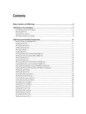
......21 Removing the Processor Fan...21 Installing the Processor Fan...22 Removing the Video-Card Fan...22 Installing the Video-Card Fan...22 Removing the Keyboard Trim...22 Installing the...
......21 Removing the Processor Fan...21 Installing the Processor Fan...22 Removing the Video-Card Fan...22 Installing the Video-Card Fan...22 Removing the Keyboard Trim...22 Installing the...
Owner's Manual
Page 4
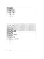
Removing the Keyboard...24 Installing the Keyboard...26 Removing the Primary Memory...26 Installing the Primary Memory...27 Removing the Secondary Memory...27 Installing the Secondary Memory...28 Removing the Bluetooth Module......
Removing the Keyboard...24 Installing the Keyboard...26 Removing the Primary Memory...26 Installing the Primary Memory...27 Removing the Secondary Memory...27 Installing the Secondary Memory...28 Removing the Bluetooth Module......
Owner's Manual
Page 22
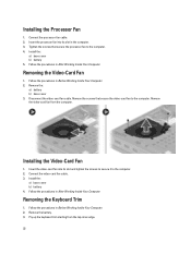
... a) battery b) base cover 3. Installing the Video-Card Fan 1. Install the: a) base cover b) battery 4. Remove the battery. 3. Pry up the keyboard trim starting from the computer. Installing the Processor Fan 1. Follow the procedures in Before Working Inside Your Computer. 2. Insert the video-card fan into its... video-card fan cable. Install the: a) base cover b) battery 5. Follow the procedures in After Working Inside Your Computer. Removing the Keyboard Trim 1. Remove the video-card fan from the top-inner edge. 22 Removing the Video-Card Fan 1. Remove the screws that secure ...
... a) battery b) base cover 3. Installing the Video-Card Fan 1. Install the: a) base cover b) battery 4. Remove the battery. 3. Pry up the keyboard trim starting from the computer. Installing the Processor Fan 1. Follow the procedures in Before Working Inside Your Computer. 2. Insert the video-card fan into its... video-card fan cable. Install the: a) base cover b) battery 5. Follow the procedures in After Working Inside Your Computer. Removing the Keyboard Trim 1. Remove the video-card fan from the top-inner edge. 22 Removing the Video-Card Fan 1. Remove the screws that secure ...
Owner's Manual
Page 23
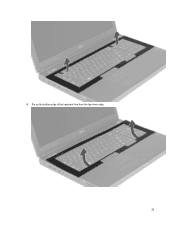
Pry up the bottom edge of the keyboard trim from the top-inner edge. 23 4.
Pry up the bottom edge of the keyboard trim from the top-inner edge. 23 4.
Owner's Manual
Page 24
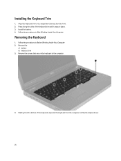
Installing the Keyboard Trim 1. Install the battery. 4. Follow the procedures in Before Working Inside Your Computer. 2. Remove the screws that secure the keyboard to its compartment starting from the bottom of the keyboard trim until it snaps in place. 3. Follow the procedures in After Working Inside Your Computer. Align the keyboard trim to the computer. 4. Press along the sides of the keyboard, separate the keyboard from the computer and flip the keyboard over. 24 Removing the Keyboard 1. Starting from the front. 2. Remove the: a) battery b) keyboard trim 3.
Installing the Keyboard Trim 1. Install the battery. 4. Follow the procedures in Before Working Inside Your Computer. 2. Remove the screws that secure the keyboard to its compartment starting from the bottom of the keyboard trim until it snaps in place. 3. Follow the procedures in After Working Inside Your Computer. Align the keyboard trim to the computer. 4. Press along the sides of the keyboard, separate the keyboard from the computer and flip the keyboard over. 24 Removing the Keyboard 1. Starting from the front. 2. Remove the: a) battery b) keyboard trim 3.
Owner's Manual
Page 25
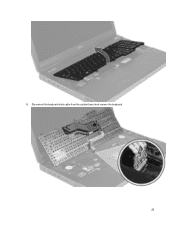
Disconnect the keyboard-data cable from the system board and remove the keyboard. 25 5.
Disconnect the keyboard-data cable from the system board and remove the keyboard. 25 5.
Owner's Manual
Page 26
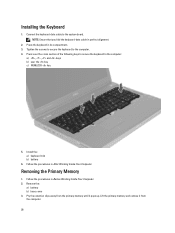
.... 26 Follow the procedures in Before Working Inside Your Computer. 2. Press the keyboard in perfect alignment. 2. Removing the Primary Memory 1. Installing the Keyboard 1. Tighten the screws to secure the keyboard to the system board. Remove the: a) battery b) base cover 3. Install the: a) keyboard trim b) battery 6. Lift the primary memory and remove it pops up. Connect...
.... 26 Follow the procedures in Before Working Inside Your Computer. 2. Press the keyboard in perfect alignment. 2. Removing the Primary Memory 1. Installing the Keyboard 1. Tighten the screws to secure the keyboard to the system board. Remove the: a) battery b) base cover 3. Install the: a) keyboard trim b) battery 6. Lift the primary memory and remove it pops up. Connect...

Owner's Manual
Page 27
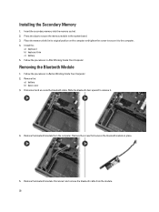
... b) battery 4. Follow the procedures in After Working Inside Your Computer. Insert the primary memory into the memory socket. 2. Removing the Secondary Memory 1. Remove the: a) battery b) keyboard trim c) keyboard 3. Lift up .
... b) battery 4. Follow the procedures in After Working Inside Your Computer. Insert the primary memory into the memory socket. 2. Removing the Secondary Memory 1. Remove the: a) battery b) keyboard trim c) keyboard 3. Lift up .
Owner's Manual
Page 28
... in After Working Inside Your Computer. Follow the procedures in its original position on the computer and tighten the screw to secure it . 4. Install the: a) keyboard b) keyboard trim c) battery 5. Remove the: a) battery b) base cover 3.
... in After Working Inside Your Computer. Follow the procedures in its original position on the computer and tighten the screw to secure it . 4. Install the: a) keyboard b) keyboard trim c) battery 5. Remove the: a) battery b) base cover 3.
Owner's Manual
Page 34
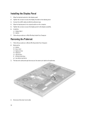
... cable to the display assembly. 6. Install the: a) display bezel b) battery 7. Follow the procedures in Before Working Inside Your Computer. 2. Remove the: a) battery b) base cover c) keyboard trim d) keyboard e) optical drive f) primary hard drive g) secondary hard drive 3. Installing the Display Panel 1. Tighten the screws to secure the display panel to the palmrest. 4. Tighten the...
... cable to the display assembly. 6. Install the: a) display bezel b) battery 7. Follow the procedures in Before Working Inside Your Computer. 2. Remove the: a) battery b) base cover c) keyboard trim d) keyboard e) optical drive f) primary hard drive g) secondary hard drive 3. Installing the Display Panel 1. Tighten the screws to secure the display panel to the palmrest. 4. Tighten the...
Owner's Manual
Page 39
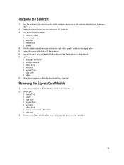
... Before Working Inside Your Computer. 2. Removing the ExpressCard Module 1. Remove the: a) ExpressCard b) battery c) base cover d) keyboard trim e) keyboard f) optical drive g) primary and secondary hard drive h) palm rest 3. Install the: a) secondary hard drive b) primary hard drive c) optical drive d) keyboard e) keyboard trim f) base cover g) battery 8. Tighten the screw that secures it snaps in place. 2. Affix the...
... Before Working Inside Your Computer. 2. Removing the ExpressCard Module 1. Remove the: a) ExpressCard b) battery c) base cover d) keyboard trim e) keyboard f) optical drive g) primary and secondary hard drive h) palm rest 3. Install the: a) secondary hard drive b) primary hard drive c) optical drive d) keyboard e) keyboard trim f) base cover g) battery 8. Tighten the screw that secures it snaps in place. 2. Affix the...
Owner's Manual
Page 40
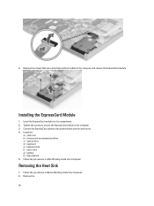
Insert the ExpressCard module into its compartment. 2. Install the: a) palm rest b) primary and secondary hard drive c) optical drive d) keyboard e) keyboard trim f) base cover g) battery h) ExpressCard 5. Follow the procedures in Before Working Inside Your Computer. 2. Installing the ExpressCard Module 1. Tighten the screws to secure the ExpressCard ...
Insert the ExpressCard module into its compartment. 2. Install the: a) palm rest b) primary and secondary hard drive c) optical drive d) keyboard e) keyboard trim f) base cover g) battery h) ExpressCard 5. Follow the procedures in Before Working Inside Your Computer. 2. Installing the ExpressCard Module 1. Tighten the screws to secure the ExpressCard ...
Owner's Manual
Page 41
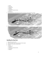
a) battery b) base cover c) keyboard trim d) keyboard e) optical drive f) primary and secondary hard drive g) palm rest h) processor fan 3. Replace the heat sink in its slot. 2. Tighten the captive screws to secure the heat sink to the computer. 4. Install the: a) processor fan b) palm rest c) primary and secondary hard drive d) optical drive e) keyboard 41 Remove the heat sink from the computer. Installing the Heat Sink 1. Disconnect the camera cable and loosen the captive screws that secure the heat sink to the computer. 3. Connect the camera cable to the system board. 4.
a) battery b) base cover c) keyboard trim d) keyboard e) optical drive f) primary and secondary hard drive g) palm rest h) processor fan 3. Replace the heat sink in its slot. 2. Tighten the captive screws to secure the heat sink to the computer. 4. Install the: a) processor fan b) palm rest c) primary and secondary hard drive d) optical drive e) keyboard 41 Remove the heat sink from the computer. Installing the Heat Sink 1. Disconnect the camera cable and loosen the captive screws that secure the heat sink to the computer. 3. Connect the camera cable to the system board. 4.
Owner's Manual
Page 42
f) keyboard trim g) base cover h) battery 5. Follow the procedures in After Working Inside Your Computer. Removing the Processor 1. Follow the procedures in After Working Inside ... Inside Your Computer. 2. Install the: a) heat sink b) processor fan c) palm rest d) primary and secondary hard drive e) optical drive f) keyboard g) keyboard trim h) base cover i) battery 4. Remove the: a) battery b) base cover c) keyboard trim d) keyboard e) optical drive f) primary and secondary hard drive g) palm rest h) processor fan i) heat sink 3. Follow the procedures in a counter-clockwise ...
f) keyboard trim g) base cover h) battery 5. Follow the procedures in After Working Inside Your Computer. Removing the Processor 1. Follow the procedures in After Working Inside ... Inside Your Computer. 2. Install the: a) heat sink b) processor fan c) palm rest d) primary and secondary hard drive e) optical drive f) keyboard g) keyboard trim h) base cover i) battery 4. Remove the: a) battery b) base cover c) keyboard trim d) keyboard e) optical drive f) primary and secondary hard drive g) palm rest h) processor fan i) heat sink 3. Follow the procedures in a counter-clockwise ...
Owner's Manual
Page 43
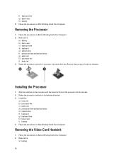
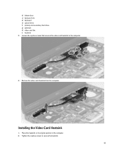
Installing the Video-Card Heatsink 1. Place the heatsink on its original position in the computer. 2. Tighten the captive screws to the computer. 4. Loosen the captive screws that secures the video-card heatsink to secure the heatsink. 43 Remove the video-card heatsink from the computer. b) bottom door c) keyboard trim d) keyboard e) optical drive f) primary and secondary hard drive g) palmrest h) video-card fan i) heatsink 3.
Installing the Video-Card Heatsink 1. Place the heatsink on its original position in the computer. 2. Tighten the captive screws to the computer. 4. Loosen the captive screws that secures the video-card heatsink to secure the heatsink. 43 Remove the video-card heatsink from the computer. b) bottom door c) keyboard trim d) keyboard e) optical drive f) primary and secondary hard drive g) palmrest h) video-card fan i) heatsink 3.
Owner's Manual
Page 44
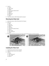
... Remove the screws that secure the video card to the computer. 3. Tighten the screws to secure it to the computer. Remove the: a) battery b) base cover c) keyboard trim d) keyboard e) optical drive f) primary and secondary hard drive g) palm rest h) video-card fan i) video-card heat sink j) heatsink 3. Installing the Video Card 1. Install the: a) heatsink...
... Remove the screws that secure the video card to the computer. 3. Tighten the screws to secure it to the computer. Remove the: a) battery b) base cover c) keyboard trim d) keyboard e) optical drive f) primary and secondary hard drive g) palm rest h) video-card fan i) video-card heat sink j) heatsink 3. Installing the Video Card 1. Install the: a) heatsink...


