Owner's Manual
Page 3
... Network (WWAN) Card (Optional 16 Removing the Optical Drive...16 Installing the Optical Drive...17 Removing the Primary Hard Drive...18 Installing the Primary Hard Drive...19 Removing the Secondary Hard Drive...19 Installing the Secondary Hard Drive...20 Removing the Coin-Cell Battery...20 Installing the Coin-Cell Battery...21 Removing the Processor Fan...21 Installing the Processor Fan...22 Removing the Video-Card...
... Network (WWAN) Card (Optional 16 Removing the Optical Drive...16 Installing the Optical Drive...17 Removing the Primary Hard Drive...18 Installing the Primary Hard Drive...19 Removing the Secondary Hard Drive...19 Installing the Secondary Hard Drive...20 Removing the Coin-Cell Battery...20 Installing the Coin-Cell Battery...21 Removing the Processor Fan...21 Installing the Processor Fan...22 Removing the Video-Card...
Owner's Manual
Page 18
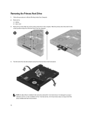
... the computer. 4. Remove the: a) battery b) base cover 3. Slide the primary hard drive latch to the hard-drive bracket for correct installation of the 7 mm hard drives. 9 mm hard drives does not require the filler when installed into hard-drive bracket. 18 Remove the screws that secure the primary hard drive to prevent vibrations and for 7 mm hard drives. NOTE: A rubber filler is designed to the computer.
... the computer. 4. Remove the: a) battery b) base cover 3. Slide the primary hard drive latch to the hard-drive bracket for correct installation of the 7 mm hard drives. 9 mm hard drives does not require the filler when installed into hard-drive bracket. 18 Remove the screws that secure the primary hard drive to prevent vibrations and for 7 mm hard drives. NOTE: A rubber filler is designed to the computer.
Owner's Manual
Page 19
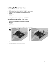
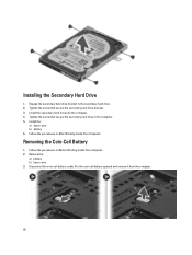
... the primary hard drive to the primary hard . 2. Remove the secondary hard drive from the computer. 5. Engage the primary hard drive bracket to the computer. 4. Removing the Secondary Hard Drive 1. Remove the screw that secondary hard drive in After Working Inside Your Computer. Follow the procedures in place. 4. Remove the screw that secure that secure secondary hard drive to the bracket. 6. Installing the Primary Hard Drive 1.
... the primary hard drive to the primary hard . 2. Remove the secondary hard drive from the computer. 5. Engage the primary hard drive bracket to the computer. 4. Removing the Secondary Hard Drive 1. Remove the screw that secondary hard drive in After Working Inside Your Computer. Follow the procedures in place. 4. Remove the screw that secure that secure secondary hard drive to the bracket. 6. Installing the Primary Hard Drive 1.
Owner's Manual
Page 20
... the coin-cell battery upward and remove it from the computer. 20 Tighten the screw that secure the secondary hard drive bracket. 3. Remove the: a) battery b) base cover 3. Follow the procedures in Before Working Inside Your Computer. 2. Tighten the screw that secure the secondary hard drive in the computer. 5. Install the: a) base cover b) battery 6. Installing the Secondary Hard Drive 1.
... the coin-cell battery upward and remove it from the computer. 20 Tighten the screw that secure the secondary hard drive bracket. 3. Remove the: a) battery b) base cover 3. Follow the procedures in Before Working Inside Your Computer. 2. Tighten the screw that secure the secondary hard drive in the computer. 5. Install the: a) base cover b) battery 6. Installing the Secondary Hard Drive 1.
Owner's Manual
Page 34
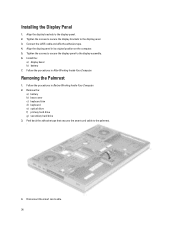
... display panel to the display panel. 2. Removing the Palmrest 1. Peel back the adhesive tape that secures the smart card cable to the display panel. 3. Install the: a) display bezel b) battery 7. Follow the procedures in its original position on the computer. 5. Disconnect the smart card cable. 34 Connect the LVDS... brackets to the palmrest. 4. Follow the procedures in Before Working Inside Your Computer. 2. Remove the: a) battery b) base cover c) keyboard trim d) keyboard e) optical drive f) primary hard drive g) secondary hard drive 3. Installing the Display Panel 1.
... display panel to the display panel. 2. Removing the Palmrest 1. Peel back the adhesive tape that secures the smart card cable to the display panel. 3. Install the: a) display bezel b) battery 7. Follow the procedures in its original position on the computer. 5. Disconnect the smart card cable. 34 Connect the LVDS... brackets to the palmrest. 4. Follow the procedures in Before Working Inside Your Computer. 2. Remove the: a) battery b) base cover c) keyboard trim d) keyboard e) optical drive f) primary hard drive g) secondary hard drive 3. Installing the Display Panel 1.
Owner's Manual
Page 39
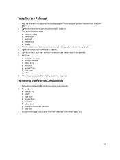
...smart card. 39 Connect the following cables: a) bluetooth module b) power button c) touchpad d) media board e) speaker 4. Install the: a) secondary hard drive b) primary hard drive c) optical drive d) keyboard e) keyboard trim f) base cover g) battery 8. Tighten the screw at the bottom of the computer. 6. ...Remove the: a) ExpressCard b) battery c) base cover d) keyboard trim e) keyboard f) optical drive g) primary and secondary hard drive h) palm rest 3. Installing the Palmrest 1. Affix the adhesive tape that secures it snaps in place. 2. Align the palmrest to the...
...smart card. 39 Connect the following cables: a) bluetooth module b) power button c) touchpad d) media board e) speaker 4. Install the: a) secondary hard drive b) primary hard drive c) optical drive d) keyboard e) keyboard trim f) base cover g) battery 8. Tighten the screw at the bottom of the computer. 6. ...Remove the: a) ExpressCard b) battery c) base cover d) keyboard trim e) keyboard f) optical drive g) primary and secondary hard drive h) palm rest 3. Installing the Palmrest 1. Affix the adhesive tape that secures it snaps in place. 2. Align the palmrest to the...
Owner's Manual
Page 40
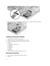
Remove the screws that secure the ExpressCard module to the computer 3. Installing the ExpressCard Module 1. Tighten the screws to secure the ExpressCard module to the computer and remove the ExpressCard module. Removing the Heat Sink 1. Follow ... to the system board and the smart card. 4. Follow the procedures in Before Working Inside Your Computer. 2. Insert the ExpressCard module into its compartment. 2. Install the: a) palm rest b) primary and secondary hard drive c) optical drive d) keyboard e) keyboard trim f) base cover g) battery h) ExpressCard 5. 4. Remove the: 40
Remove the screws that secure the ExpressCard module to the computer 3. Installing the ExpressCard Module 1. Tighten the screws to secure the ExpressCard module to the computer and remove the ExpressCard module. Removing the Heat Sink 1. Follow ... to the system board and the smart card. 4. Follow the procedures in Before Working Inside Your Computer. 2. Insert the ExpressCard module into its compartment. 2. Install the: a) palm rest b) primary and secondary hard drive c) optical drive d) keyboard e) keyboard trim f) base cover g) battery h) ExpressCard 5. 4. Remove the: 40
Owner's Manual
Page 41
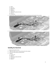
Remove the heat sink from the computer. Install the: a) processor fan b) palm rest c) primary and secondary hard drive d) optical drive e) keyboard 41 Disconnect the camera cable and loosen the captive screws that secure the heat sink to the computer. 3. Replace the heat sink in its slot. 2. Installing the Heat Sink 1. a) battery b) base cover c) keyboard trim d) keyboard e) optical drive f) primary and secondary hard drive g) palm rest h) processor fan 3. Tighten the captive screws to secure the heat sink to the computer. 4. Connect the camera cable to the system board. 4.
Remove the heat sink from the computer. Install the: a) processor fan b) palm rest c) primary and secondary hard drive d) optical drive e) keyboard 41 Disconnect the camera cable and loosen the captive screws that secure the heat sink to the computer. 3. Replace the heat sink in its slot. 2. Installing the Heat Sink 1. a) battery b) base cover c) keyboard trim d) keyboard e) optical drive f) primary and secondary hard drive g) palm rest h) processor fan 3. Tighten the captive screws to secure the heat sink to the computer. 4. Connect the camera cable to the system board. 4.
Owner's Manual
Page 42
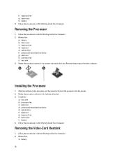
...5. Follow the procedures in Before Working Inside Your Computer. 2. Removing the Processor 1. Installing the Processor 1. Install the: a) heat sink b) processor fan c) palm rest d) primary and secondary hard drive e) optical drive f) keyboard g) keyboard trim h) base cover i) battery 4. Removing the Video-Card ...insert the processor into the socket. 2. Remove the: a) battery b) base cover c) keyboard trim d) keyboard e) optical drive f) primary and secondary hard drive g) palm rest h) processor fan i) heat sink 3. Remove the processor from the computer. Follow the procedures in a ...
...5. Follow the procedures in Before Working Inside Your Computer. 2. Removing the Processor 1. Installing the Processor 1. Install the: a) heat sink b) processor fan c) palm rest d) primary and secondary hard drive e) optical drive f) keyboard g) keyboard trim h) base cover i) battery 4. Removing the Video-Card ...insert the processor into the socket. 2. Remove the: a) battery b) base cover c) keyboard trim d) keyboard e) optical drive f) primary and secondary hard drive g) palm rest h) processor fan i) heat sink 3. Remove the processor from the computer. Follow the procedures in a ...
Owner's Manual
Page 43
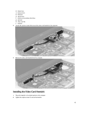
Tighten the captive screws to the computer. 4. Place the heatsink on its original position in the computer. 2. Remove the video-card heatsink from the computer. Loosen the captive screws that secures the video-card heatsink to secure the heatsink. 43 Installing the Video-Card Heatsink 1. b) bottom door c) keyboard trim d) keyboard e) optical drive f) primary and secondary hard drive g) palmrest h) video-card fan i) heatsink 3.
Tighten the captive screws to the computer. 4. Place the heatsink on its original position in the computer. 2. Remove the video-card heatsink from the computer. Loosen the captive screws that secures the video-card heatsink to secure the heatsink. 43 Installing the Video-Card Heatsink 1. b) bottom door c) keyboard trim d) keyboard e) optical drive f) primary and secondary hard drive g) palmrest h) video-card fan i) heatsink 3.
Owner's Manual
Page 44
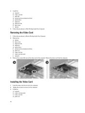
...the video card to the computer. 3. Tighten the screws to secure it to the computer. Install the: a) heatsink b) video-card fan c) palmrest d) primary and secondary hard drive e) optical drive f) keyboard g) keyboard trim h) base cover i) battery 4. Follow the procedures in Before Working ...Inside Your Computer. 2. Remove the video card from the computer. Install the: a) heatsink b) video-card heat sink c) video...
...the video card to the computer. 3. Tighten the screws to secure it to the computer. Install the: a) heatsink b) video-card fan c) palmrest d) primary and secondary hard drive e) optical drive f) keyboard g) keyboard trim h) base cover i) battery 4. Follow the procedures in Before Working ...Inside Your Computer. 2. Remove the video card from the computer. Install the: a) heatsink b) video-card heat sink c) video...
Owner's Manual
Page 46
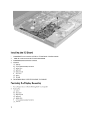
... connector. 4. Follow the procedures in the computer. 2. Remove the: a) battery b) base cover c) keyboard trim d) keyboard e) optical drive f) primary and secondary hard drive g) palmrest 46 Installing the I /O board to secure the I /O Board 1. Install the: a) palmrest b) primary and secondary hard drive c) optical drive d) keyboard e) keyboard trim f) base cover g) battery h) SD card 5. Tighten the screws to the computer. 3. Follow the procedures...
... connector. 4. Follow the procedures in the computer. 2. Remove the: a) battery b) base cover c) keyboard trim d) keyboard e) optical drive f) primary and secondary hard drive g) palmrest 46 Installing the I /O board to secure the I /O Board 1. Install the: a) palmrest b) primary and secondary hard drive c) optical drive d) keyboard e) keyboard trim f) base cover g) battery h) SD card 5. Tighten the screws to the computer. 3. Follow the procedures...
Owner's Manual
Page 49
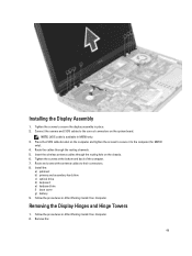
... the routing hole on the system board. Insert the wireless antenna cables through the routing channels. 5. Follow the procedures in M6700 only. 3. NOTE: LVDS cable is available in After Working Inside Your Computer. 2. Connect the camera and LVDS cables to the computer (.... Removing the Display Hinges and Hinge Towers 1. Tighten the screws to their connectors. 8. Follow the procedures in place. 2. Installing the Display Assembly 1. Install the: a) palmrest b) primary and secondary hard drive c) optical drive d) keyboard e) keyboard trim f) base cover g) battery 9.
... the routing hole on the system board. Insert the wireless antenna cables through the routing channels. 5. Follow the procedures in M6700 only. 3. NOTE: LVDS cable is available in After Working Inside Your Computer. 2. Connect the camera and LVDS cables to the computer (.... Removing the Display Hinges and Hinge Towers 1. Tighten the screws to their connectors. 8. Follow the procedures in place. 2. Installing the Display Assembly 1. Install the: a) palmrest b) primary and secondary hard drive c) optical drive d) keyboard e) keyboard trim f) base cover g) battery 9.
Owner's Manual
Page 50
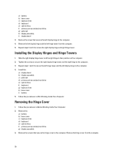
... to remove the right display hinge and right hinge tower. Remove the: a) battery b) base cover c) keyboard trim d) keyboard e) optical drive f) primary and secondary hard drive g) display assembly 3. Remove the hinge cover from the computer. 5. Installing the Display Hinges and Hinge Towers 1. Removing the Hinge Cover 1. Slide the right display hinge tower and the right...
... to remove the right display hinge and right hinge tower. Remove the: a) battery b) base cover c) keyboard trim d) keyboard e) optical drive f) primary and secondary hard drive g) display assembly 3. Remove the hinge cover from the computer. 5. Installing the Display Hinges and Hinge Towers 1. Removing the Hinge Cover 1. Slide the right display hinge tower and the right...
Owner's Manual
Page 51
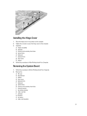
... memory k) video-card fan l) palmrest m) heatsink n) processor o) video-card heatsink. 51 Place the hinge cover in Before Working Inside Your Computer. 2. Install the: a) display assembly b) palmrest c) primary and secondary hard drive d) optical drive e) keyboard f) keyboard trim g) base cover h) battery 4. Follow the procedures in its position on the computer. 2. Follow the procedures in After Working...
... memory k) video-card fan l) palmrest m) heatsink n) processor o) video-card heatsink. 51 Place the hinge cover in Before Working Inside Your Computer. 2. Install the: a) display assembly b) palmrest c) primary and secondary hard drive d) optical drive e) keyboard f) keyboard trim g) base cover h) battery 4. Follow the procedures in its position on the computer. 2. Follow the procedures in After Working...
Owner's Manual
Page 55
... power connector port from the computer. 55 d) processor e) heatsink f) palmrest g) video-card fan h) secondary memory i) primary memory j) primary and secondary hard drive k) optical drive l) keyboard m) keyboard trim n) base cover o) battery p) ExpressCard q) SD card 7. Install all the mini-cards (if available). 5. Follow the procedures in Before Working Inside Your Computer. 2. Place the LVDS cable bracket...
... power connector port from the computer. 55 d) processor e) heatsink f) palmrest g) video-card fan h) secondary memory i) primary memory j) primary and secondary hard drive k) optical drive l) keyboard m) keyboard trim n) base cover o) battery p) ExpressCard q) SD card 7. Install all the mini-cards (if available). 5. Follow the procedures in Before Working Inside Your Computer. 2. Place the LVDS cable bracket...
Owner's Manual
Page 56
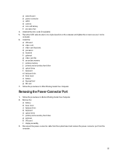
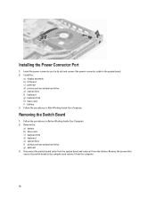
... it from the computer. 56 Insert the power-connector port in Before Working Inside Your Computer. 2. Install the: a) display assembly b) I/O board c) palmrest d) primary and secondary hard drive e) optical drive f) keyboard g) keyboard trim h) base cover i) battery 3. Follow the procedures in After Working Inside ...remove it from the latches. Remove the: a) battery b) base cover c) keyboard trim d) keyboard e) optical drive f) primary and secondary hard drive g) palmrest 3. Installing the Power Connector Port 1. Remove the screws that secure the switch board to the system board. 2.
... it from the computer. 56 Insert the power-connector port in Before Working Inside Your Computer. 2. Install the: a) display assembly b) I/O board c) palmrest d) primary and secondary hard drive e) optical drive f) keyboard g) keyboard trim h) base cover i) battery 3. Follow the procedures in After Working Inside ...remove it from the latches. Remove the: a) battery b) base cover c) keyboard trim d) keyboard e) optical drive f) primary and secondary hard drive g) palmrest 3. Installing the Power Connector Port 1. Remove the screws that secure the switch board to the system board. 2.
Owner's Manual
Page 57
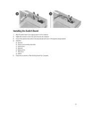
Connect the switch-board cable to the computer. 3. Install the: a) palmrest b) primary and secondary hard drive c) optical drive d) keyboard e) keyboard trim f) base cover g) battery 5. Follow the procedures in After Working Inside Your Computer. 57 Tighten the screws to secure the switch board to the system board and secure it through the routing channel. 4. Align the switch board to its original position on the computer. 2. Installing the Switch Board 1.
Connect the switch-board cable to the computer. 3. Install the: a) palmrest b) primary and secondary hard drive c) optical drive d) keyboard e) keyboard trim f) base cover g) battery 5. Follow the procedures in After Working Inside Your Computer. 57 Tighten the screws to secure the switch board to the system board and secure it through the routing channel. 4. Align the switch board to its original position on the computer. 2. Installing the Switch Board 1.
Owner's Manual
Page 73
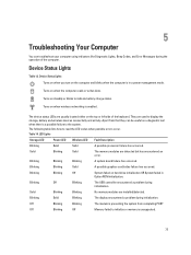
...completing POST Off Blinking Off Memory failed to initialize or memory is unsupported. 73 Solid Blinking Solid The memory modules are installed/detected. Blinking Off Blinking The USB controller encountered a problem during initialization. Device Status Lights Table 13. Turns on the...Blinking Off System failed on steadily or blinks to display the storage, battery and wireless devices connectivity and activity. Turns on hard drive initialization OR System failed in a power management mode. LED Lights Storage LED Power LED Wireless LED Fault Description Blinking Solid...
...completing POST Off Blinking Off Memory failed to initialize or memory is unsupported. 73 Solid Blinking Solid The memory modules are installed/detected. Blinking Off Blinking The USB controller encountered a problem during initialization. Device Status Lights Table 13. Turns on the...Blinking Off System failed on steadily or blinks to display the storage, battery and wireless devices connectivity and activity. Turns on hard drive initialization OR System failed in a power management mode. LED Lights Storage LED Power LED Wireless LED Fault Description Blinking Solid...


