User Manual
Page 1
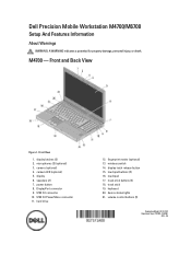
...9. wireless switch 14. keyboard 20. Dell Precision Mobile Workstation M4700/M6700 Setup And Features Information About Warnings WARNING: A WARNING indicates a potential for property damage, personal injury, or death. Front and Back View Figure 1. USB 3.0 PowerShare connector 11. M4700 - microphones (2) (optional) 3. display 6. speakers (2) 7. touchpad buttons (3) 16. track stick 19. camera LED (optional) 5. USB 3.0 connector 10. fingerprint reader (optional) 13. display latch release button 15. track-stick buttons (3) 18. volume control buttons (3) Regulatory Model...
...9. wireless switch 14. keyboard 20. Dell Precision Mobile Workstation M4700/M6700 Setup And Features Information About Warnings WARNING: A WARNING indicates a potential for property damage, personal injury, or death. Front and Back View Figure 1. USB 3.0 PowerShare connector 11. M4700 - microphones (2) (optional) 3. display 6. speakers (2) 7. touchpad buttons (3) 16. track stick 19. camera LED (optional) 5. USB 3.0 connector 10. fingerprint reader (optional) 13. display latch release button 15. track-stick buttons (3) 18. volume control buttons (3) Regulatory Model...
User Manual
Page 3
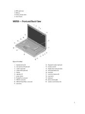
...HDD eject latch 3. battery release latch 5. camera (optional) 4. track-stick buttons (3) 18. display 6. fingerprint reader (optional) 13. wireless switch 14. keyboard 20. camera LED (optional) 5. DisplayPort connector 9. USB 3.0 connector 10. display-latch release button 15. device status lights 21. Front and Back View Figure 4. speakers (2) 7. USB 3.0 PowerShare connector 11. touchpad 17. microphones (2) (optional) 3. power button 8. 2. display latches (2) 2. Front View 1. touchpad buttons (3) 16. SIM slot 4. dock I/O port M6700 - hard drive...
...HDD eject latch 3. battery release latch 5. camera (optional) 4. track-stick buttons (3) 18. display 6. fingerprint reader (optional) 13. wireless switch 14. keyboard 20. camera LED (optional) 5. DisplayPort connector 9. USB 3.0 connector 10. display-latch release button 15. device status lights 21. Front and Back View Figure 4. speakers (2) 7. USB 3.0 PowerShare connector 11. touchpad 17. microphones (2) (optional) 3. power button 8. 2. display latches (2) 2. Front View 1. touchpad buttons (3) 16. SIM slot 4. dock I/O port M6700 - hard drive...
User Manual
Page 5
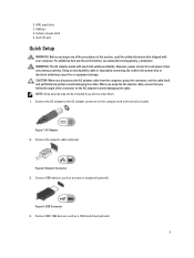
... cause fire or equipment damage. Connect the AC adapter to the AC adapter connector on the AC adapter to avoid damaging the cable. Connect USB devices, such as a 1394 hard drive (optional). 5 Connect IEEE 1394 devices, such as a mouse or keyboard (optional). HDD eject latch 3. dock I/O port Quick Setup WARNING: Before you did not order them. 1. AC Adapter 2. Figure 9. Figure 8. Using an incompatible cable or improperly connecting the cable to the power strip or electrical outlet may...
... cause fire or equipment damage. Connect the AC adapter to the AC adapter connector on the AC adapter to avoid damaging the cable. Connect USB devices, such as a 1394 hard drive (optional). 5 Connect IEEE 1394 devices, such as a mouse or keyboard (optional). HDD eject latch 3. dock I/O port Quick Setup WARNING: Before you did not order them. 1. AC Adapter 2. Figure 9. Figure 8. Using an incompatible cable or improperly connecting the cable to the power strip or electrical outlet may...
Statement of Volatility
Page 1
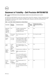
... present on System Board Description Reference Designator Volatility Description User Accessible for keyboard controller BIOS code, asset tag and BIOS passwords Panel EEDID EEPROM System BIOS Part of data and tells you how to four modules must be populated. U52 (8M) U53 (4M) Non Volatile memory, 32 Mbit No (4 MB) and 64 Mbit (8 MB), System BIOS and Video BIOS for correct operation of embedded Flash No memory for external data Remedial...
... present on System Board Description Reference Designator Volatility Description User Accessible for keyboard controller BIOS code, asset tag and BIOS passwords Panel EEDID EEPROM System BIOS Part of data and tells you how to four modules must be populated. U52 (8M) U53 (4M) Non Volatile memory, 32 Mbit No (4 MB) and 64 Mbit (8 MB), System BIOS and Video BIOS for correct operation of embedded Flash No memory for external data Remedial...
Statement of Volatility
Page 2
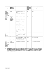
... Dell Inc. Hard drive(s) User Non Volatile magnetic media, Yes replaceable - be SSD (solid state flash drive). frame buffer UH4 On GFx cards (nVidia N14x and AMD): Non Volatile memory, 64 No Bytes. User Non Volatile optical media. Primary power loss (unplugging the power cord and removing the battery) destroys all user data on the system board lose data if power is removed from the system. Secondary power loss (removing the on-board...
... Dell Inc. Hard drive(s) User Non Volatile magnetic media, Yes replaceable - be SSD (solid state flash drive). frame buffer UH4 On GFx cards (nVidia N14x and AMD): Non Volatile memory, 64 No Bytes. User Non Volatile optical media. Primary power loss (unplugging the power cord and removing the battery) destroys all user data on the system board lose data if power is removed from the system. Secondary power loss (removing the on-board...
Owner's Manual
Page 4
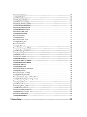
... Video Card...44 Installing the Video Card...44 Removing the Input/Output (I/O) Board...45 Installing the I/O Board...46 Removing the Display Assembly...46 Installing the Display Assembly...49 Removing the Display Hinges and Hinge Towers 49 Installing the Display Hinges and Hinge Towers...50 Removing the Hinge Cover...50 Installing the Hinge Cover...51 Removing the System Board...51 Installing the System Board...54 Removing the Power-Connector Port...55 Installing the Power Connector Port...56 Removing the Switch Board...56 Installing the Switch Board...57 3 System Setup...
... Video Card...44 Installing the Video Card...44 Removing the Input/Output (I/O) Board...45 Installing the I/O Board...46 Removing the Display Assembly...46 Installing the Display Assembly...49 Removing the Display Hinges and Hinge Towers 49 Installing the Display Hinges and Hinge Towers...50 Removing the Hinge Cover...50 Installing the Hinge Cover...51 Removing the System Board...51 Installing the System Board...54 Removing the Power-Connector Port...55 Installing the Power Connector Port...56 Removing the Switch Board...56 Installing the Switch Board...57 3 System Setup...
Owner's Manual
Page 7
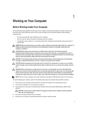
... troubleshooting and simple repairs as authorized in your work surface is connected to a docking device (docked) such as a processor by its edges, not by a certified service technician. To avoid damaging your computer and certain components may only be replaced or--if purchased separately--installed by its pins. Hold a card by its edges or by performing the removal procedure in reverse order...
... troubleshooting and simple repairs as authorized in your work surface is connected to a docking device (docked) such as a processor by its edges, not by a certified service technician. To avoid damaging your computer and certain components may only be replaced or--if purchased separately--installed by its pins. Hold a card by its edges or by performing the removal procedure in reverse order...
Owner's Manual
Page 9
... media base, and replace any telephone or network cables to your computer. 9 Connect your computer. Replace the battery. 4. After Working Inside Your Computer After you complete any replacement procedure, ensure you connect any external devices, cards, and cables before turning on your computer. Turn on your computer and all attached devices to their electrical outlets. 5. CAUTION: To avoid damage to the computer, use batteries designed for this particular Dell computer...
... media base, and replace any telephone or network cables to your computer. 9 Connect your computer. Replace the battery. 4. After Working Inside Your Computer After you complete any replacement procedure, ensure you connect any external devices, cards, and cables before turning on your computer. Turn on your computer and all attached devices to their electrical outlets. 5. CAUTION: To avoid damage to the computer, use batteries designed for this particular Dell computer...
Owner's Manual
Page 31
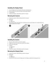
... Computer. 2. Remove the: a) battery b) display bezel 3. Flip the display panel over. 31 Toe-in its slot on the display bezel. 2. Removing the Camera 1. Remove the: a) battery b) display bezel 3. Connect the camera cable. 4. Disconnect the camera cable. Installing the Camera 1. Place the camera module in the display bezel from the computer. Remove the screw that secures the camera module to the display assembly. Follow the procedures in Before Working Inside Your Computer. 2. Remove the screw that secures the display panel to...
... Computer. 2. Remove the: a) battery b) display bezel 3. Flip the display panel over. 31 Toe-in its slot on the display bezel. 2. Removing the Camera 1. Remove the: a) battery b) display bezel 3. Connect the camera cable. 4. Disconnect the camera cable. Installing the Camera 1. Place the camera module in the display bezel from the computer. Remove the screw that secures the camera module to the display assembly. Follow the procedures in Before Working Inside Your Computer. 2. Remove the screw that secures the display panel to...
Owner's Manual
Page 34
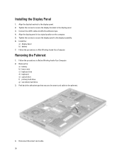
Install the: a) display bezel b) battery 7. Follow the procedures in Before Working Inside Your Computer. 2. Removing the Palmrest 1. Remove the: a) battery b) base cover c) keyboard trim d) keyboard e) optical drive f) primary hard drive g) secondary hard drive 3. Follow the procedures in After Working Inside Your Computer. Disconnect the smart card cable. 34 Align the display brackets to the display panel. 3. Connect the LVDS cable and affix the adhesive tape. 4. Align the display panel in its original position on the computer...
Install the: a) display bezel b) battery 7. Follow the procedures in Before Working Inside Your Computer. 2. Removing the Palmrest 1. Remove the: a) battery b) base cover c) keyboard trim d) keyboard e) optical drive f) primary hard drive g) secondary hard drive 3. Follow the procedures in After Working Inside Your Computer. Disconnect the smart card cable. 34 Align the display brackets to the display panel. 3. Connect the LVDS cable and affix the adhesive tape. 4. Align the display panel in its original position on the computer...
Owner's Manual
Page 39
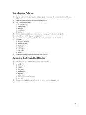
...After Working Inside Your Computer. Follow the procedures in Before Working Inside Your Computer. 2. Disconnect the ExpressCard cables from both the system board and the smart card. 39 Removing the ExpressCard Module 1. Remove the: a) ExpressCard b) battery c) base cover d) keyboard trim e) keyboard f) optical drive g) primary and secondary hard drive h) palm rest 3. Tighten the screw that secures the media card cable, speaker cable and touchpad cable. 5. Installing the Palmrest 1. Connect the following cables: a) bluetooth module b) power button c) touchpad d) media board e) speaker...
...After Working Inside Your Computer. Follow the procedures in Before Working Inside Your Computer. 2. Disconnect the ExpressCard cables from both the system board and the smart card. 39 Removing the ExpressCard Module 1. Remove the: a) ExpressCard b) battery c) base cover d) keyboard trim e) keyboard f) optical drive g) primary and secondary hard drive h) palm rest 3. Tighten the screw that secures the media card cable, speaker cable and touchpad cable. 5. Installing the Palmrest 1. Connect the following cables: a) bluetooth module b) power button c) touchpad d) media board e) speaker...
Owner's Manual
Page 59
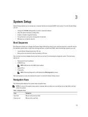
... hardware configuration • Enable or disable integrated devices • Set performance and power management thresholds • Manage your computer hardware and specify BIOS‐level options. From the System Setup, you can : • Access System Setup by pressing key • Bring up the one-time boot menu by pressing key The one-time boot menu displays the devices that you make are : • Removable Drive (if available) • STXXXX Drive NOTE: XXX denotes the SATA drive number. • Optical Drive...
... hardware configuration • Enable or disable integrated devices • Set performance and power management thresholds • Manage your computer hardware and specify BIOS‐level options. From the System Setup, you can : • Access System Setup by pressing key • Bring up the one-time boot menu by pressing key The one-time boot menu displays the devices that you make are : • Removable Drive (if available) • STXXXX Drive NOTE: XXX denotes the SATA drive number. • Optical Drive...
Owner's Manual
Page 60
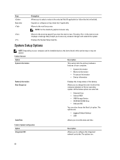
...; System Information • Memory Information • Processor Information • Device Information Battery Information Boot Sequence Displays the charge status of the battery. System Configuration Option Integrated NIC Description Allows you to save any unsaved changes and restarts the system. Moves to set the date and time. Pressing in the main screen displays a message that prompts you to configure the integrated network controller. General Option System Information Description...
...; System Information • Memory Information • Processor Information • Device Information Battery Information Boot Sequence Displays the charge status of the battery. System Configuration Option Integrated NIC Description Allows you to save any unsaved changes and restarts the system. Moves to set the date and time. Pressing in the main screen displays a message that prompts you to configure the integrated network controller. General Option System Information Description...
Owner's Manual
Page 62
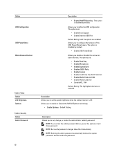
...Ports • Enable Camera • Enable Hard Drive Free Fall Protection • Enable Media Card and 1394 • Enable Media Card Only • Disable MC, 1394 Default Setting: The highlighted devices are enabled. Description Allows you to configure the behavior of the USB PowerShare feature. Security Option Admin Password 62 Description • Enable SMART Reporting - The options are: • Enable Boot Support • Enable External USB Port Default Setting: both the options are enabled. NOTE: You must set the admin password before you enable or disable the various on board...
...Ports • Enable Camera • Enable Hard Drive Free Fall Protection • Enable Media Card and 1394 • Enable Media Card Only • Disable MC, 1394 Default Setting: The highlighted devices are enabled. Description Allows you to configure the behavior of the USB PowerShare feature. Security Option Admin Password 62 Description • Enable SMART Reporting - The options are: • Enable Boot Support • Enable External USB Port Default Setting: both the options are enabled. NOTE: You must set the admin password before you enable or disable the various on board...
Owner's Manual
Page 63
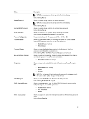
... set . Default Setting: Not set Allows you to prevent users from entering Setup when an Administrator password is set strong passwords. Default Setting: Enable Strong Password is set , change or delete the administrator password. The option is disabled. • Allows Wireless Switch Changes Allows you to activate or disable the optional Computrace software The options are : • Enable (Default Setting) • One Time Enable • Disable Allows you to enable or disable the permission to enter the Option ROM Configuration screens using hotkeys during boot process. The options...
... set . Default Setting: Not set Allows you to prevent users from entering Setup when an Administrator password is set strong passwords. Default Setting: Enable Strong Password is set , change or delete the administrator password. The option is disabled. • Allows Wireless Switch Changes Allows you to activate or disable the optional Computrace software The options are : • Enable (Default Setting) • One Time Enable • Disable Allows you to enable or disable the permission to enter the Option ROM Configuration screens using hotkeys during boot process. The options...
Owner's Manual
Page 66
... NumLock function can be controlled by default. • Enable Keyboard Error Detection Specifies whether the sign-on screen displays a message, that displays the keystroke sequence required to enable or disable the wireless devices. This option is enabled by the wireless switch. The option is enabled by default. • Enable Fn Key Emulation Specifies whether keyboard related errors are reported when it boots. Description Allows you to enter the BIOS Boot Option Menu. • Enable F12 Boot Option menu - Description This option specifies whether a Virtual Machine Monitor...
... NumLock function can be controlled by default. • Enable Keyboard Error Detection Specifies whether the sign-on screen displays a message, that displays the keystroke sequence required to enable or disable the wireless devices. This option is enabled by the wireless switch. The option is enabled by default. • Enable Fn Key Emulation Specifies whether keyboard related errors are reported when it boots. Description Allows you to enter the BIOS Boot Option Menu. • Enable F12 Boot Option menu - Description This option specifies whether a Virtual Machine Monitor...
Owner's Manual
Page 67
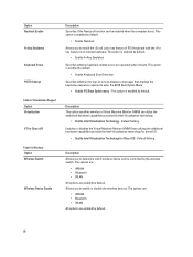
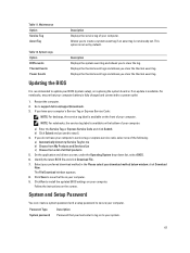
... and drivers screen, under the Operating System drop-down list, select BIOS. 6. The File Download window appears. 8. System and Setup Password You can create a system password and a setup password to clear the log. System Logs Option BIOS events Thermal Events Power Events Description Displays the system event log and allows you must enter to log on the front of your computer. 9. Maintenance Option Service Tag Asset Tag Description Displays the service tag of all Dell...
... and drivers screen, under the Operating System drop-down list, select BIOS. 6. The File Download window appears. 8. System and Setup Password You can create a system password and a setup password to clear the log. System Logs Option BIOS events Thermal Events Power Events Description Displays the system event log and allows you must enter to log on the front of your computer. 9. Maintenance Option Service Tag Asset Tag Description Displays the service tag of all Dell...
Owner's Manual
Page 68
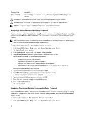
... or . Use the following special characters are not allowed. - To enter the System Setup, press immediately after a power-on your computer. A message prompts you to delete or change the System Password. NOTE: If the password jumper is disabled, the existing System Password and Setup Password is not locked and left unattended. The System Security screen appears. 2. Type the setup password that Password Status is Unlocked. The computer reboots. Press...
... or . Use the following special characters are not allowed. - To enter the System Setup, press immediately after a power-on your computer. A message prompts you to delete or change the System Password. NOTE: If the password jumper is disabled, the existing System Password and Setup Password is not locked and left unattended. The System Security screen appears. 2. Type the setup password that Password Status is Unlocked. The computer reboots. Press...
Owner's Manual
Page 71
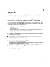
... to fix the problem yourself, service and support personnel can use the diagnostics results to test only your computer. Note the error code and contact Dell. 71 If you solve the problem. Select the device from the left pane and click Run Tests. 6. Using this program with the BIOS and is displayed, listing all the detected devices. 4. NOTE: Some tests for technical assistance. On the boot menu screen...
... to fix the problem yourself, service and support personnel can use the diagnostics results to test only your computer. Note the error code and contact Dell. 71 If you solve the problem. Select the device from the left pane and click Run Tests. 6. Using this program with the BIOS and is displayed, listing all the detected devices. 4. NOTE: Some tests for technical assistance. On the boot menu screen...
Owner's Manual
Page 73
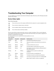
... LED codes when possible errors occur. Table 14. Blinking Blinking Solid A possible graphics card/video failure has occurred. 5 Troubleshooting Your Computer You can be useful as a diagnostic tool when there's a possible failure to the system. The following table lists how to display the storage, battery and wireless devices connectivity and activity. Turns on when wireless networking is unsupported. 73 Apart from completing POST Off Blinking Off Memory failed to indicate battery charge status. Solid Blinking Blinking No memory modules...
... LED codes when possible errors occur. Table 14. Blinking Blinking Solid A possible graphics card/video failure has occurred. 5 Troubleshooting Your Computer You can be useful as a diagnostic tool when there's a possible failure to the system. The following table lists how to display the storage, battery and wireless devices connectivity and activity. Turns on when wireless networking is unsupported. 73 Apart from completing POST Off Blinking Off Memory failed to indicate battery charge status. Solid Blinking Blinking No memory modules...


