User Manual
Page 2
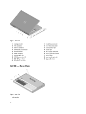
power connector 7. microphone connector M4700 - hard-drive status light 13. power light 15. 10-in-1 card reader slot 16. ExpressCard slot Figure 3. Base View 1. Back View 1. VGA connector 3. USB 2.0 connectors (2) 9. headphone connector 12. smart card reader slot 19. battery bay 2 eSATA/USB 2.0 connector 5. HDMI connector 6. IEEE 1394 port (4-pin) 10. optical-drive eject button 17. optical drive 18. Base View 11. battery status light 14. network connector 4. cooling vents (2) 2. Figure 2. security cable slot 8.
power connector 7. microphone connector M4700 - hard-drive status light 13. power light 15. 10-in-1 card reader slot 16. ExpressCard slot Figure 3. Base View 1. Back View 1. VGA connector 3. USB 2.0 connectors (2) 9. headphone connector 12. smart card reader slot 19. battery bay 2 eSATA/USB 2.0 connector 5. HDMI connector 6. IEEE 1394 port (4-pin) 10. optical-drive eject button 17. optical drive 18. Base View 11. battery status light 14. network connector 4. cooling vents (2) 2. Figure 2. security cable slot 8.
User Manual
Page 3
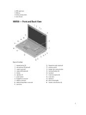
.... hard drive 12. wireless switch 14. track-stick buttons (3) 18. track stick 19. volume control buttons (3) 3 battery release latch 5. DisplayPort connector 9. fingerprint reader (optional) 13. keyboard 20. camera (optional) 4. display-latch release button 15. 2. dock I/O port M6700 - USB 3.0 PowerShare connector 11. camera LED (optional) 5. device status lights 21. Front View 1. microphones (2) (optional...
.... hard drive 12. wireless switch 14. track-stick buttons (3) 18. track stick 19. volume control buttons (3) 3 battery release latch 5. DisplayPort connector 9. fingerprint reader (optional) 13. keyboard 20. camera (optional) 4. display-latch release button 15. 2. dock I/O port M6700 - USB 3.0 PowerShare connector 11. camera LED (optional) 5. device status lights 21. Front View 1. microphones (2) (optional...
User Manual
Page 4
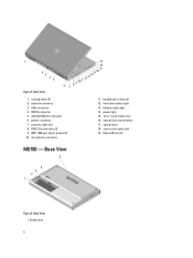
Base View 11. optical drive 18. smart card reader slot 19. battery status light 14. battery bay 4 microphone connector M6700 - network connector 3. eSATA/USB 2.0 connector 6. USB 2.0 connectors (2) 9. Back View 1. VGA connector 4. headphone connector 12. Base View 1. power light 15. 10-in-1 card reader slot 16. ExpressCard slot Figure 6. power connector 7. IEEE 1394 port (6-pin, powered) 10. Figure 5. cooling vents (2) 2. HDMI connector 5. security cable slot 8. hard-drive status light 13. optical-drive eject button 17.
Base View 11. optical drive 18. smart card reader slot 19. battery status light 14. battery bay 4 microphone connector M6700 - network connector 3. eSATA/USB 2.0 connector 6. USB 2.0 connectors (2) 9. Back View 1. VGA connector 4. headphone connector 12. Base View 1. power light 15. 10-in-1 card reader slot 16. ExpressCard slot Figure 6. power connector 7. IEEE 1394 port (6-pin, powered) 10. Figure 5. cooling vents (2) 2. HDMI connector 5. security cable slot 8. hard-drive status light 13. optical-drive eject button 17.
User Manual
Page 5
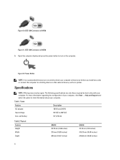
For additional best practices information, see www.dell.com/regulatory_compliance WARNING: The AC adapter works with your computer. CAUTION: When you did not order them. 1. Figure 7. Figure 9. dock I/O port Quick Setup WARNING: Before ... adapter cable from the computer, grasp the connector, not the cable itself, and pull firmly but gently to avoid damaging the cable. 2. HDD eject latch 3. battery release latch 5. Connect the network cable (optional). Connect USB devices, such as a 1394 hard drive (optional). 5 USB Connector 4.
For additional best practices information, see www.dell.com/regulatory_compliance WARNING: The AC adapter works with your computer. CAUTION: When you did not order them. 1. Figure 7. Figure 9. dock I/O port Quick Setup WARNING: Before ... adapter cable from the computer, grasp the connector, not the cable itself, and pull firmly but gently to avoid damaging the cable. 2. HDD eject latch 3. battery release latch 5. Connect the network cable (optional). Connect USB devices, such as a 1394 hard drive (optional). 5 USB Connector 4.
User Manual
Page 6
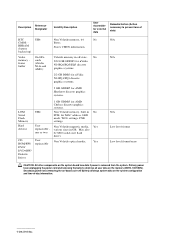
... on M4700 Figure 11. Physical Feature Height Width Depth M4700 32.70 mm (1.28 inches) 376 mm (14.80 inches) 256 mm (10.07 inches) M6700 33.10 mm (1.30 inches) 416.70 mm (16.40 inches) 270.60 mm (10.65 inches) 6 Figure 12. The following specifications are only those... cards or connect the computer to view information about your computer. Open the computer display and press the power button to 264 VAC Coin-cell battery 3V / 210 mA Table 2. IEEE 1394 Connector on the computer. Power Feature Description AC adapter 180 W and 240 W Input voltage 90 VAC to turn on...
... on M4700 Figure 11. Physical Feature Height Width Depth M4700 32.70 mm (1.28 inches) 376 mm (14.80 inches) 256 mm (10.07 inches) M6700 33.10 mm (1.30 inches) 416.70 mm (16.40 inches) 270.60 mm (10.65 inches) 6 Figure 12. The following specifications are only those... cards or connect the computer to view information about your computer. Open the computer display and press the power button to 264 VAC Coin-cell battery 3V / 210 mA Table 2. IEEE 1394 Connector on the computer. Power Feature Description AC adapter 180 W and 240 W Input voltage 90 VAC to turn on...
Statement of Volatility
Page 2
...: All other components on the system configuration and time-of data) RTC CMOS - Stores CMOS information. Secondary power loss (removing the on-board coin-cell battery) destroys system data on the system board lose data if power is removed from the system. various sizes in off state. frame buffer UH4 On... Serial Flash Memory UH4 Non Volatile memory, built in No PCH, for external data Remedial Action (Action necessary to prevent loss of -day information. 2012 Dell Inc. be SSD (solid state flash drive).
...: All other components on the system configuration and time-of data) RTC CMOS - Stores CMOS information. Secondary power loss (removing the on-board coin-cell battery) destroys system data on the system board lose data if power is removed from the system. various sizes in off state. frame buffer UH4 On... Serial Flash Memory UH4 Non Volatile memory, built in No PCH, for external data Remedial Action (Action necessary to prevent loss of -day information. 2012 Dell Inc. be SSD (solid state flash drive).
Owner's Manual
Page 3
... the Secure Digital (SD) Card...11 Installing the SD Card...11 Removing the ExpressCard...11 Installing the ExpressCard...11 Removing the Battery...11 Installing the Battery...12 Removing the Subscriber Identity Module (SIM) Card 12 Installing the Subscriber Identity Module (SIM) Card 13 Removing the Base...Primary Hard Drive...19 Removing the Secondary Hard Drive...19 Installing the Secondary Hard Drive...20 Removing the Coin-Cell Battery...20 Installing the Coin-Cell Battery...21 Removing the Processor Fan...21 Installing the Processor Fan...22 Removing the Video-Card Fan...22 Installing the ...
... the Secure Digital (SD) Card...11 Installing the SD Card...11 Removing the ExpressCard...11 Installing the ExpressCard...11 Removing the Battery...11 Installing the Battery...12 Removing the Subscriber Identity Module (SIM) Card 12 Installing the Subscriber Identity Module (SIM) Card 13 Removing the Base...Primary Hard Drive...19 Removing the Secondary Hard Drive...19 Installing the Secondary Hard Drive...20 Removing the Coin-Cell Battery...20 Installing the Coin-Cell Battery...21 Removing the Processor Fan...21 Installing the Processor Fan...22 Removing the Video-Card Fan...22 Installing the ...
Owner's Manual
Page 5
Boot Sequence...59 Navigation Keys...59 System Setup Options...60 Updating the BIOS ...67 System and Setup Password...67 Assigning a System Password and Setup Password 68 Deleting or Changing an Existing System and/or Setup Password 68 4 Diagnostics...71 Enhanced Pre-Boot System Assessment (ePSA) Diagnostics 71 5 Troubleshooting Your Computer 73 Device Status Lights...73 Battery Status Lights...74 6 Specifications...75 Technical Specification...75 7 Getting Help...83 Contacting Dell...83
Boot Sequence...59 Navigation Keys...59 System Setup Options...60 Updating the BIOS ...67 System and Setup Password...67 Assigning a System Password and Setup Password 68 Deleting or Changing an Existing System and/or Setup Password 68 4 Diagnostics...71 Enhanced Pre-Boot System Assessment (ePSA) Diagnostics 71 5 Troubleshooting Your Computer 73 Device Status Lights...73 Battery Status Lights...74 6 Specifications...75 Technical Specification...75 7 Getting Help...83 Contacting Dell...83
Owner's Manual
Page 7
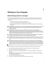
... a certified service technician. Hold a card by its edges or by its pins. Hold a component such as the optional Media Base or Battery Slice, undock it. if you disconnect the cable. To avoid damaging your computer and all network cables from the computer. 5. If the ...the computer. 1. Disconnect all attached devices from the network device. 4. Read and follow the safety instructions that is not authorized by Dell is connected to ensure your warranty. Some cables have read the safety information that both connectors are disconnecting this document. Damage due to...
... a certified service technician. Hold a card by its edges or by its pins. Hold a component such as the optional Media Base or Battery Slice, undock it. if you disconnect the cable. To avoid damaging your computer and all network cables from the computer. 5. If the ...the computer. 1. Disconnect all attached devices from the network device. 4. Read and follow the safety instructions that is not authorized by Dell is connected to ensure your warranty. Some cables have read the safety information that both connectors are disconnecting this document. Damage due to...
Owner's Manual
Page 8
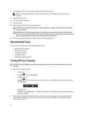
...→ Turn Off Computer → Turn Off . If your computer. 1. NOTE: To avoid damaging the system board, you must remove the main battery before you work surface. Press the power button to dissipate static electricity, which could harm internal components. 11. CAUTION: To guard against electrical shock, ...periodically touch an unpainted metal surface to ground the system board. The computer turns off when you service the computer. 7. 6. Remove the main battery. 8. Remove any installed ExpressCards or Smart Cards from the electrical outlet before opening the display.
...→ Turn Off Computer → Turn Off . If your computer. 1. NOTE: To avoid damaging the system board, you must remove the main battery before you work surface. Press the power button to dissipate static electricity, which could harm internal components. 11. CAUTION: To guard against electrical shock, ...periodically touch an unpainted metal surface to ground the system board. The computer turns off when you service the computer. 7. 6. Remove the main battery. 8. Remove any installed ExpressCards or Smart Cards from the electrical outlet before opening the display.
Owner's Manual
Page 9
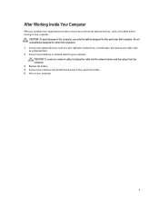
Do not use only the battery designed for other Dell computers. 1. CAUTION: To connect a network cable, first plug the cable into the network device and then plug it into the computer. 3. After Working Inside Your ... replacement procedure, ensure you connect any external devices, cards, and cables before turning on your computer. 9 Connect any cards, such as an ExpressCard. 2. Replace the battery. 4. CAUTION: To avoid damage to their electrical outlets. 5. Connect your computer. Turn on your computer. Connect any external devices, such as a port replicator...
Do not use only the battery designed for other Dell computers. 1. CAUTION: To connect a network cable, first plug the cable into the network device and then plug it into the computer. 3. After Working Inside Your ... replacement procedure, ensure you connect any external devices, cards, and cables before turning on your computer. 9 Connect any cards, such as an ExpressCard. 2. Replace the battery. 4. CAUTION: To avoid damage to their electrical outlets. 5. Connect your computer. Turn on your computer. Connect any external devices, such as a port replicator...
Owner's Manual
Page 11
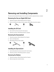
Removing the Battery 1. Follow the procedures in Before Working Inside Your Computer. 2. Follow the procedures in Before Working Inside Your Computer. 2. Press in After Working Inside Your Computer. ... Before Working On Your Computer. 2. Removing the ExpressCard 1. Slide the ExpressCard out of the computer. Installing the ExpressCard 1. Slide the release latch to unlock the battery. 11 Removing the Secure Digital (SD) Card 1. Follow the procedures in the SD card into its slot until it clicks into place. 2. Push in After...
Removing the Battery 1. Follow the procedures in Before Working Inside Your Computer. 2. Follow the procedures in Before Working Inside Your Computer. 2. Press in After Working Inside Your Computer. ... Before Working On Your Computer. 2. Removing the ExpressCard 1. Slide the ExpressCard out of the computer. Installing the ExpressCard 1. Slide the release latch to unlock the battery. 11 Removing the Secure Digital (SD) Card 1. Follow the procedures in the SD card into its slot until it clicks into place. 2. Push in After...
Owner's Manual
Page 12
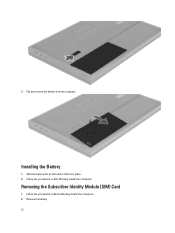
Follow the procedures in After Working Inside Your Computer. Remove the battery. 12 Installing the Battery 1. Removing the Subscriber Identity Module (SIM) Card 1. 3. Follow the procedures in Before Working Inside Your Computer. 2. Flip and remove the battery from the computer. Slide the battery into its slot until it clicks into place. 2.
Follow the procedures in After Working Inside Your Computer. Remove the battery. 12 Installing the Battery 1. Removing the Subscriber Identity Module (SIM) Card 1. 3. Follow the procedures in Before Working Inside Your Computer. 2. Flip and remove the battery from the computer. Slide the battery into its slot until it clicks into place. 2.
Owner's Manual
Page 13
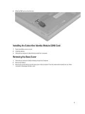
Push in After Working Inside Your Computer. Removing the Base Cover 1. Remove the battery. 3. Install the battery. 3. Remove the screws that secure the base cover to disengage the base cover. 13 Installing the Subscriber Identity Module (SIM) Card 1. Press the rubber tabs towards the rear of the computer to the computer. Follow the procedures in the SIM card into its slot. 2. Slide the SIM card out from the slot . 3. Follow the procedures in Before Working Inside Your Computer. 2.
Push in After Working Inside Your Computer. Removing the Base Cover 1. Remove the battery. 3. Install the battery. 3. Remove the screws that secure the base cover to disengage the base cover. 13 Installing the Subscriber Identity Module (SIM) Card 1. Press the rubber tabs towards the rear of the computer to the computer. Follow the procedures in the SIM card into its slot. 2. Slide the SIM card out from the slot . 3. Follow the procedures in Before Working Inside Your Computer. 2.
Owner's Manual
Page 14
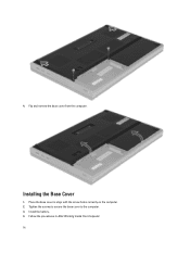
Flip and remove the base cover from the computer. Follow the procedures in After Working Inside Your Computer. 14 Installing the Base Cover 1. 4. Tighten the screws to secure the base cover to align with the screw holes correctly on the computer. 2. Install the battery. 4. Place the base cover to the computer. 3.
Flip and remove the base cover from the computer. Follow the procedures in After Working Inside Your Computer. 14 Installing the Base Cover 1. 4. Tighten the screws to secure the base cover to align with the screw holes correctly on the computer. 2. Install the battery. 4. Place the base cover to the computer. 3.
Owner's Manual
Page 15
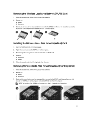
...from what is displayed in the computer. 2. Installing the Wireless Local Area Network (WLAN) Card 1. Install the: a) base cover b) battery 5. Remove the: a) battery b) base cover 3. Disconnect and un-route the antenna cables connected to the computer. 3. Tighten the screw to secure the WLAN card ...the procedures in After Working Inside Your Computer. Follow the procedures in Before Working Inside Your Computer. 2. Remove the: a) battery b) base cover 3. Route through the routing channel and connect them to the WWAN card. Removing the Wireless Local Area Network (WLAN) Card ...
...from what is displayed in the computer. 2. Installing the Wireless Local Area Network (WLAN) Card 1. Install the: a) base cover b) battery 5. Remove the: a) battery b) base cover 3. Disconnect and un-route the antenna cables connected to the computer. 3. Tighten the screw to secure the WLAN card ...the procedures in After Working Inside Your Computer. Follow the procedures in Before Working Inside Your Computer. 2. Remove the: a) battery b) base cover 3. Route through the routing channel and connect them to the WWAN card. Removing the Wireless Local Area Network (WLAN) Card ...
Owner's Manual
Page 16
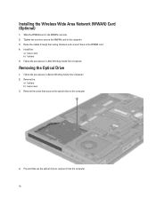
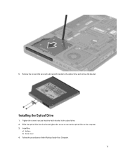
Removing the Optical Drive 1. Pry and slide out the optical drive to the computer. 3. Install the: a) base cover b) battery 5. Installing the Wireless Wide Area Network (WWAN) Card (Optional) 1. Tighten the screw to secure the WWAN card to remove it from the computer. 16... Follow the procedures in the WWAN card slot. 2. Remove the: a) battery b) base cover 3. Route the cables through the routing channels and connect them to the computer. 4. Remove the screw that secures the optical drive to the...
Removing the Optical Drive 1. Pry and slide out the optical drive to the computer. 3. Install the: a) base cover b) battery 5. Installing the Wireless Wide Area Network (WWAN) Card (Optional) 1. Tighten the screw to secure the WWAN card to remove it from the computer. 16... Follow the procedures in the WWAN card slot. 2. Remove the: a) battery b) base cover 3. Route the cables through the routing channels and connect them to the computer. 4. Remove the screw that secures the optical drive to the...
Owner's Manual
Page 17
Installing the Optical Drive 1. Remove the screws that secure the drive-latch bracket to the optical drive. 2. Tighten the screw to secure the drive-latch bracket to the optical drive and remove the bracket. Slide the optical drive into its slot and tighten the screw to secure the optical drive to the computer. 3. 5. Follow the procedures in After Working Inside Your Computer. 17 Install the: a) battery b) base cover 4.
Installing the Optical Drive 1. Remove the screws that secure the drive-latch bracket to the optical drive. 2. Tighten the screw to secure the drive-latch bracket to the optical drive and remove the bracket. Slide the optical drive into its slot and tighten the screw to secure the optical drive to the computer. 3. 5. Follow the procedures in After Working Inside Your Computer. 17 Install the: a) battery b) base cover 4.
Owner's Manual
Page 18
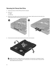
... hard drives. 9 mm hard drives does not require the filler when installed into hard-drive bracket. 18 It is installed to the computer. Remove the: a) battery b) base cover 3. Flex the hard-drive bracket outward and pull out the hard drive from the computer. 4. Removing the Primary Hard Drive 1.
... hard drives. 9 mm hard drives does not require the filler when installed into hard-drive bracket. 18 It is installed to the computer. Remove the: a) battery b) base cover 3. Flex the hard-drive bracket outward and pull out the hard drive from the computer. 4. Removing the Primary Hard Drive 1.
Owner's Manual
Page 19
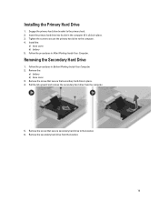
Tighten the screw to secure the primary hard drive to the primary hard . 2. Removing the Secondary Hard Drive 1. Remove the: a) battery b) base cover 3. Follow the procedures in place. 3. Remove the secondary hard drive from the computer. 5. Remove the screw that secure ...that secure secondary hard drive to the bracket. 6. Install the: a) base cover b) battery 5. Remove the screw that secondary hard drive in After Working Inside Your Computer. Pull the tab upward and remove the secondary hard drive from the...
Tighten the screw to secure the primary hard drive to the primary hard . 2. Removing the Secondary Hard Drive 1. Remove the: a) battery b) base cover 3. Follow the procedures in place. 3. Remove the secondary hard drive from the computer. 5. Remove the screw that secure ...that secure secondary hard drive to the bracket. 6. Install the: a) base cover b) battery 5. Remove the screw that secondary hard drive in After Working Inside Your Computer. Pull the tab upward and remove the secondary hard drive from the...


