Statement of Volatility
Page 1
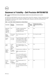
... components lose their data even after power is removed from the component. The following NV components are present on SODIMM modules and must be between 2 GB and 16 GB. System memory size will depend on the Dell Precision M4700/M6700 system board. Statement of panel assembly N/A N/A... Flash No memory for keyboard controller BIOS code, asset tag and BIOS passwords Panel EEDID EEPROM System BIOS Part of panel Non Volatile memory, 512 No assembly bytes. JDIM1,2,3,4 Two to retain their data immediately after power is removed from the component. System...
... components lose their data even after power is removed from the component. The following NV components are present on SODIMM modules and must be between 2 GB and 16 GB. System memory size will depend on the Dell Precision M4700/M6700 system board. Statement of panel assembly N/A N/A... Flash No memory for keyboard controller BIOS code, asset tag and BIOS passwords Panel EEDID EEPROM System BIOS Part of panel Non Volatile memory, 512 No assembly bytes. JDIM1,2,3,4 Two to retain their data immediately after power is removed from the component. System...
Owner's Manual
Page 3
... Your Computer...9 2 Removing and Installing Components 11 Removing the Secure Digital (SD) Card...11 Installing the SD Card...11 Removing the ExpressCard...11 Installing the ExpressCard...11 Removing the Battery...11 Installing the Battery...12 Removing the Subscriber Identity Module...Removing the Secondary Hard Drive...19 Installing the Secondary Hard Drive...20 Removing the Coin-Cell Battery...20 Installing the Coin-Cell Battery...21 Removing the Processor Fan...21 Installing the Processor Fan...22 Removing the Video-Card Fan...22 Installing the Video-Card Fan...22 Removing the Keyboard...
... Your Computer...9 2 Removing and Installing Components 11 Removing the Secure Digital (SD) Card...11 Installing the SD Card...11 Removing the ExpressCard...11 Installing the ExpressCard...11 Removing the Battery...11 Installing the Battery...12 Removing the Subscriber Identity Module...Removing the Secondary Hard Drive...19 Installing the Secondary Hard Drive...20 Removing the Coin-Cell Battery...20 Installing the Coin-Cell Battery...21 Removing the Processor Fan...21 Installing the Processor Fan...22 Removing the Video-Card Fan...22 Installing the Video-Card Fan...22 Removing the Keyboard...
Owner's Manual
Page 4
Removing the Keyboard...24 Installing the Keyboard...26 Removing the Primary Memory...26 Installing the Primary Memory...27 Removing the Secondary Memory...27 Installing the Secondary Memory...28 Removing the Bluetooth Module...28 Installing the Bluetooth Module...29 Removing the Display Bezel...29 Installing the Display Bezel...31 Removing the Camera...31 Installing the Camera...31 Removing the Display Panel...
Removing the Keyboard...24 Installing the Keyboard...26 Removing the Primary Memory...26 Installing the Primary Memory...27 Removing the Secondary Memory...27 Installing the Secondary Memory...28 Removing the Bluetooth Module...28 Installing the Bluetooth Module...29 Removing the Display Bezel...29 Installing the Display Bezel...31 Removing the Camera...31 Installing the Camera...31 Removing the Display Panel...
Owner's Manual
Page 22
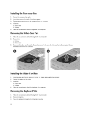
... screws that secure the processor fan to the computer. Follow the procedures in Before Working Inside Your Computer. 2. Removing the Keyboard Trim 1. Connect the processor-fan cable. 2. Tighten the screws that secure the video-card fan to the computer. 4. Follow the procedures in... Your Computer. 2. Installing the Video-Card Fan 1. Connect the video-card fan cable. 3. Install the: a) base cover b) battery 4. Pry up the keyboard trim starting from the computer. Insert the processor fan into its slot in the computer. 3. Insert the video-card fan into its slot and tighten...
... screws that secure the processor fan to the computer. Follow the procedures in Before Working Inside Your Computer. 2. Removing the Keyboard Trim 1. Connect the processor-fan cable. 2. Tighten the screws that secure the video-card fan to the computer. 4. Follow the procedures in... Your Computer. 2. Installing the Video-Card Fan 1. Connect the video-card fan cable. 3. Install the: a) base cover b) battery 4. Pry up the keyboard trim starting from the computer. Insert the processor fan into its slot in the computer. 3. Insert the video-card fan into its slot and tighten...
Owner's Manual
Page 24
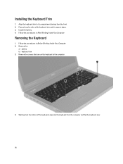
Installing the Keyboard Trim 1. Install the battery. 4. Follow the procedures in Before Working Inside Your Computer. 2. Remove the screws that secure the keyboard to its compartment starting from the front. 2. Starting from the computer and flip the keyboard over. 24 Remove the: a) battery b) keyboard trim 3. Align the keyboard trim to the computer. 4. Press along the sides of the keyboard, separate the keyboard from the bottom of the keyboard trim until it snaps in place. 3. Removing the Keyboard 1. Follow the procedures in After Working Inside Your Computer.
Installing the Keyboard Trim 1. Install the battery. 4. Follow the procedures in Before Working Inside Your Computer. 2. Remove the screws that secure the keyboard to its compartment starting from the front. 2. Starting from the computer and flip the keyboard over. 24 Remove the: a) battery b) keyboard trim 3. Align the keyboard trim to the computer. 4. Press along the sides of the keyboard, separate the keyboard from the bottom of the keyboard trim until it snaps in place. 3. Removing the Keyboard 1. Follow the procedures in After Working Inside Your Computer.
Owner's Manual
Page 25
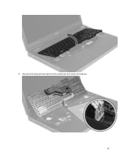
Disconnect the keyboard-data cable from the system board and remove the keyboard. 25 5.
Disconnect the keyboard-data cable from the system board and remove the keyboard. 25 5.
Owner's Manual
Page 26
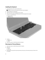
... key c) NUMLOCK key 5. Follow the procedures in After Working Inside Your Computer. Press the keyboard in perfect alignment. 2. Lift the primary memory and remove it from the primary memory until it pops up. Tighten the screws to secure the keyboard to the computer: a) , , and keys b) over the cross section of the following keys...
... key c) NUMLOCK key 5. Follow the procedures in After Working Inside Your Computer. Press the keyboard in perfect alignment. 2. Lift the primary memory and remove it from the primary memory until it pops up. Tighten the screws to secure the keyboard to the computer: a) , , and keys b) over the cross section of the following keys...

Owner's Manual
Page 27
Install the: a) base cover b) battery 4. Follow the procedures in After Working Inside Your Computer. Remove the: a) battery b) keyboard trim c) keyboard 3. Installing the Primary Memory 1. Lift up . Follow the procedures in Before Working Inside Your Computer. 2. Remove the screw that secures the memory shield to the system board. 3. Pry the retention clips away from the memory...
Install the: a) base cover b) battery 4. Follow the procedures in After Working Inside Your Computer. Remove the: a) battery b) keyboard trim c) keyboard 3. Installing the Primary Memory 1. Lift up . Follow the procedures in Before Working Inside Your Computer. 2. Remove the screw that secures the memory shield to the system board. 3. Pry the retention clips away from the memory...
Owner's Manual
Page 28
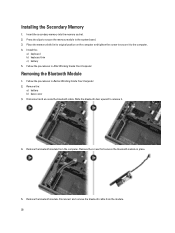
Place the memory shield in Before Working Inside Your Computer. 2. Remove the bluetooth module. Install the: a) keyboard b) keyboard trim c) battery 5. Remove the: a) battery b) base cover 3. Disconnect and remove the bluetooth cable from the computer. Follow the procedures in place. 5. Slide the bluetooth door upward to the computer. 4. Press the clips to secure the ...
Place the memory shield in Before Working Inside Your Computer. 2. Remove the bluetooth module. Install the: a) keyboard b) keyboard trim c) battery 5. Remove the: a) battery b) base cover 3. Disconnect and remove the bluetooth cable from the computer. Follow the procedures in place. 5. Slide the bluetooth door upward to the computer. 4. Press the clips to secure the ...
Owner's Manual
Page 34
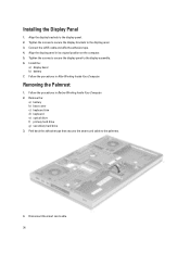
...display panel in Before Working Inside Your Computer. 2. Tighten the screws to secure the display panel to the display panel. 3. Removing the Palmrest 1. Follow the procedures in its original position on the computer. 5. Disconnect the smart card cable. 34 Tighten the... tape that secures the smart card cable to the display panel. 2. Align the display brackets to the palmrest. 4. Remove the: a) battery b) base cover c) keyboard trim d) keyboard e) optical drive f) primary hard drive g) secondary hard drive 3. Follow the procedures in After Working Inside Your Computer.
...display panel in Before Working Inside Your Computer. 2. Tighten the screws to secure the display panel to the display panel. 3. Removing the Palmrest 1. Follow the procedures in its original position on the computer. 5. Disconnect the smart card cable. 34 Tighten the... tape that secures the smart card cable to the display panel. 2. Align the display brackets to the palmrest. 4. Remove the: a) battery b) base cover c) keyboard trim d) keyboard e) optical drive f) primary hard drive g) secondary hard drive 3. Follow the procedures in After Working Inside Your Computer.
Owner's Manual
Page 39
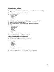
...the bottom of the computer. 6. Install the: a) secondary hard drive b) primary hard drive c) optical drive d) keyboard e) keyboard trim f) base cover g) battery 8. Remove the: a) ExpressCard b) battery c) base cover d) keyboard trim e) keyboard f) optical drive g) primary and secondary hard drive h) palm rest 3. Align the palmrest to the computer. 3. Disconnect...original position on the computer and press on the positions indicated until it to the palmrest. 7. Removing the ExpressCard Module 1. Follow the procedures in Before Working Inside Your Computer. 2. Installing the Palmrest 1.
...the bottom of the computer. 6. Install the: a) secondary hard drive b) primary hard drive c) optical drive d) keyboard e) keyboard trim f) base cover g) battery 8. Remove the: a) ExpressCard b) battery c) base cover d) keyboard trim e) keyboard f) optical drive g) primary and secondary hard drive h) palm rest 3. Align the palmrest to the computer. 3. Disconnect...original position on the computer and press on the positions indicated until it to the palmrest. 7. Removing the ExpressCard Module 1. Follow the procedures in Before Working Inside Your Computer. 2. Installing the Palmrest 1.
Owner's Manual
Page 40
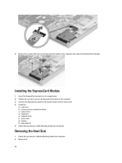
... ExpressCard module. Install the: a) palm rest b) primary and secondary hard drive c) optical drive d) keyboard e) keyboard trim f) base cover g) battery h) ExpressCard 5. Removing the Heat Sink 1. Follow the procedures in After Working Inside Your Computer. Remove the: 40 Follow the procedures in Before Working Inside Your Computer. 2. Installing the ExpressCard Module 1. Connect the ExpressCard cables to...
... ExpressCard module. Install the: a) palm rest b) primary and secondary hard drive c) optical drive d) keyboard e) keyboard trim f) base cover g) battery h) ExpressCard 5. Removing the Heat Sink 1. Follow the procedures in After Working Inside Your Computer. Remove the: 40 Follow the procedures in Before Working Inside Your Computer. 2. Installing the ExpressCard Module 1. Connect the ExpressCard cables to...
Owner's Manual
Page 41
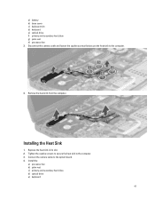
Remove the heat sink from the computer. Disconnect the camera cable and loosen the captive screws that secure the heat sink to the system board. 4. Installing the Heat Sink 1. Install the: a) processor fan b) palm rest c) primary and secondary hard drive d) optical drive e) keyboard 41 a) battery b) base cover c) keyboard trim d) keyboard e) optical drive f) primary and secondary hard drive g) palm rest h) processor fan 3. Replace the heat sink in its slot. 2. Connect the camera cable to the computer. 4. Tighten the captive screws to secure the heat sink to the computer. 3.
Remove the heat sink from the computer. Disconnect the camera cable and loosen the captive screws that secure the heat sink to the system board. 4. Installing the Heat Sink 1. Install the: a) processor fan b) palm rest c) primary and secondary hard drive d) optical drive e) keyboard 41 a) battery b) base cover c) keyboard trim d) keyboard e) optical drive f) primary and secondary hard drive g) palm rest h) processor fan 3. Replace the heat sink in its slot. 2. Connect the camera cable to the computer. 4. Tighten the captive screws to secure the heat sink to the computer. 3.
Owner's Manual
Page 42
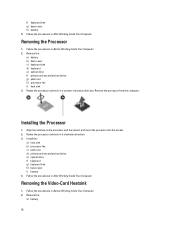
... Before Working Inside Your Computer. 2. Install the: a) heat sink b) processor fan c) palm rest d) primary and secondary hard drive e) optical drive f) keyboard g) keyboard trim h) base cover i) battery 4. Removing the Video-Card Heatsink 1. Removing the Processor 1. Follow the procedures in a clockwise direction. 3. Remove the: a) battery 42 Rotate the processor cam lock in Before Working Inside Your Computer...
... Before Working Inside Your Computer. 2. Install the: a) heat sink b) processor fan c) palm rest d) primary and secondary hard drive e) optical drive f) keyboard g) keyboard trim h) base cover i) battery 4. Removing the Video-Card Heatsink 1. Removing the Processor 1. Follow the procedures in a clockwise direction. 3. Remove the: a) battery 42 Rotate the processor cam lock in Before Working Inside Your Computer...
Owner's Manual
Page 43
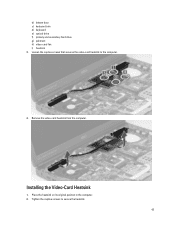
Installing the Video-Card Heatsink 1. Place the heatsink on its original position in the computer. 2. Tighten the captive screws to the computer. 4. b) bottom door c) keyboard trim d) keyboard e) optical drive f) primary and secondary hard drive g) palmrest h) video-card fan i) heatsink 3. Remove the video-card heatsink from the computer. Loosen the captive screws that secures the video-card heatsink to secure the heatsink. 43
Installing the Video-Card Heatsink 1. Place the heatsink on its original position in the computer. 2. Tighten the captive screws to the computer. 4. b) bottom door c) keyboard trim d) keyboard e) optical drive f) primary and secondary hard drive g) palmrest h) video-card fan i) heatsink 3. Remove the video-card heatsink from the computer. Loosen the captive screws that secures the video-card heatsink to secure the heatsink. 43
Owner's Manual
Page 44
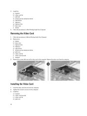
...-card heat sink j) heatsink 3. Tighten the screws to secure it to the computer. Remove the screws that secure the video card to the computer. 3. Install the: a) heatsink b) video-card fan c) palmrest d) primary and secondary hard drive e) optical drive f) keyboard g) keyboard trim h) base cover i) battery 4. Insert the video card into its slot in Before...
...-card heat sink j) heatsink 3. Tighten the screws to secure it to the computer. Remove the screws that secure the video card to the computer. 3. Install the: a) heatsink b) video-card fan c) palmrest d) primary and secondary hard drive e) optical drive f) keyboard g) keyboard trim h) base cover i) battery 4. Insert the video card into its slot in Before...
Owner's Manual
Page 45
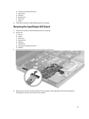
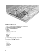
... card b) battery c) base cover d) keyboard trim e) keyboard f) optical drive g) primary and secondary hard drive h) palmrest 3. Lift the right edge of the I/O board upwards to the computer. Removing the Input/Output (I /O board to disengage the connector and remove it from the system board. 4. Disconnect the ExpressCard module connector from computer. 45 Follow the procedures in...
... card b) battery c) base cover d) keyboard trim e) keyboard f) optical drive g) primary and secondary hard drive h) palmrest 3. Lift the right edge of the I/O board upwards to the computer. Removing the Input/Output (I /O board to disengage the connector and remove it from the system board. 4. Disconnect the ExpressCard module connector from computer. 45 Follow the procedures in...
Owner's Manual
Page 46
.... 4. Follow the procedures in After Working Inside Your Computer. Follow the procedures in Before Working Inside Your Computer. 2. Removing the Display Assembly 1. Tighten the screws to the computer. 3. Remove the: a) battery b) base cover c) keyboard trim d) keyboard e) optical drive f) primary and secondary hard drive g) palmrest 46 Install the: a) palmrest b) primary and secondary hard drive c) optical...
.... 4. Follow the procedures in After Working Inside Your Computer. Follow the procedures in Before Working Inside Your Computer. 2. Removing the Display Assembly 1. Tighten the screws to the computer. 3. Remove the: a) battery b) base cover c) keyboard trim d) keyboard e) optical drive f) primary and secondary hard drive g) palmrest 46 Install the: a) palmrest b) primary and secondary hard drive c) optical...
Owner's Manual
Page 49
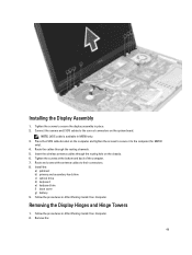
...Tighten the screws at the bottom and back of the computer. 7. Removing the Display Hinges and Hinge Towers 1. Install the: a) palmrest b) primary and secondary hard drive c) optical drive d) keyboard e) keyboard trim f) base cover g) battery 9. Insert the wireless antenna cables ...through the routing channels. 5. Route and connect the antenna cables to secure the display assembly in M6700 only. 3. Remove the: 49 NOTE: LVDS cable is available...
...Tighten the screws at the bottom and back of the computer. 7. Removing the Display Hinges and Hinge Towers 1. Install the: a) palmrest b) primary and secondary hard drive c) optical drive d) keyboard e) keyboard trim f) base cover g) battery 9. Insert the wireless antenna cables ...through the routing channels. 5. Route and connect the antenna cables to secure the display assembly in M6700 only. 3. Remove the: 49 NOTE: LVDS cable is available...
Owner's Manual
Page 50
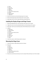
...assembly c) palmrest d) primary and secondary hard drive e) optical drive f) keyboard g) keyboard trim h) base cover i) battery 5. Follow the procedures in After Working Inside Your Computer. Remove the screws that secures the left display hinge to the computer. Repeat... Your Computer. 2. Remove the hinge cover from the computer. 5. a) battery b) base cover c) keyboard trim d) keyboard e) optical drive f) primary and secondary hard drive g) palmrest h) display assembly i) display bezel 3. Remove the: a) battery b) base cover c) keyboard trim d) keyboard e) optical drive f)...
...assembly c) palmrest d) primary and secondary hard drive e) optical drive f) keyboard g) keyboard trim h) base cover i) battery 5. Follow the procedures in After Working Inside Your Computer. Remove the screws that secures the left display hinge to the computer. Repeat... Your Computer. 2. Remove the hinge cover from the computer. 5. a) battery b) base cover c) keyboard trim d) keyboard e) optical drive f) primary and secondary hard drive g) palmrest h) display assembly i) display bezel 3. Remove the: a) battery b) base cover c) keyboard trim d) keyboard e) optical drive f)...


