Quick Reference Guide
Page 11
... Your computer is 100 V. NOTICE: In Japan, the voltage selection switch must be available on the back panel and can access connectors for any installed PCI and PCI Express cards.
... Your computer is 100 V. NOTICE: In Japan, the voltage selection switch must be available on the back panel and can access connectors for any installed PCI and PCI Express cards.
Quick Reference Guide
Page 13
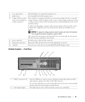
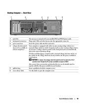
... and attached devices are electrically rated to operate with either an auto-sensing voltage selector or a (may not be set the switch for any installed PCI and PCI Express cards. 2 back-panel connectors Plug serial, USB, and other devices into the appropriate connector. 3 power connector Insert the power cable into this latch to...
... and attached devices are electrically rated to operate with either an auto-sensing voltage selector or a (may not be set the switch for any installed PCI and PCI Express cards. 2 back-panel connectors Plug serial, USB, and other devices into the appropriate connector. 3 power connector Insert the power cable into this latch to...
Quick Reference Guide
Page 15
7 power light 8 headphone connector 9 microphone connector 10 floppy drive 11 CD/DVD drive Turns on page 36 for any installed PCI and PCI Express cards. For more information about sleep modes and exiting from a power-saving mode, press the power button or use the keyboard or the mouse if ...
7 power light 8 headphone connector 9 microphone connector 10 floppy drive 11 CD/DVD drive Turns on page 36 for any installed PCI and PCI Express cards. For more information about sleep modes and exiting from a power-saving mode, press the power button or use the keyboard or the mouse if ...
Quick Reference Guide
Page 28
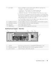
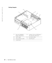
www.dell.com | support.dell.com Desktop Computer 2 1 3 4 5 7 6 1 drives bay (CD/DVD, floppy, and hard drive) 2 power supply 3 chassis intrusion switch 4 system board 5 card slots (3) for one PCI Express x16 card and two PCI cards 6 heat sink assembly 7 front I/O panel 28 Quick Reference Guide
www.dell.com | support.dell.com Desktop Computer 2 1 3 4 5 7 6 1 drives bay (CD/DVD, floppy, and hard drive) 2 power supply 3 chassis intrusion switch 4 system board 5 card slots (3) for one PCI Express x16 card and two PCI cards 6 heat sink assembly 7 front I/O panel 28 Quick Reference Guide
Setup Guide
Page 23
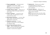
Connects to connectors on any installed PCI Express cards. 6 Service Tag and Express Service Code - NOTE: Before you buy a security cable, ensure that it fits...slot - Indicates power availability of this connector may not be available on your region. 3 Power connector - Using Your Inspiron Desktop 7 Padlock slot - Allows you to attach a standard padlock to prevent unauthorized access to the computer. Connect USB...appropriate connectors. 5 Expansion card slots - Allows you access the Dell Support website or call technical support. The appearance of the power supply.
Connects to connectors on any installed PCI Express cards. 6 Service Tag and Express Service Code - NOTE: Before you buy a security cable, ensure that it fits...slot - Indicates power availability of this connector may not be available on your region. 3 Power connector - Using Your Inspiron Desktop 7 Padlock slot - Allows you to attach a standard padlock to prevent unauthorized access to the computer. Connect USB...appropriate connectors. 5 Expansion card slots - Allows you access the Dell Support website or call technical support. The appearance of the power supply.

Setup Guide
Page 64
Specifications Internal Connectors PCI Express x1 PCI Express x16 three 36-pin connectors one 164-pin connector SATA four 7-pin connectors External Connectors Audio: Front panel one stereo headphones/speakers connector and one microphone-in connector Back panel three connectors for 5.1 channel support Network adapter one RJ45 connector External Connectors USB two front-panel and six back-panel USB 2.0 compliant connectors VGA one 15-hole connector HDMI one 19-pin connector Media Card Reader one 8-in-1 card reader Battery Type 3 V CR-2032 lithium coin-cell 62
Specifications Internal Connectors PCI Express x1 PCI Express x16 three 36-pin connectors one 164-pin connector SATA four 7-pin connectors External Connectors Audio: Front panel one stereo headphones/speakers connector and one microphone-in connector Back panel three connectors for 5.1 channel support Network adapter one RJ45 connector External Connectors USB two front-panel and six back-panel USB 2.0 compliant connectors VGA one 15-hole connector HDMI one 19-pin connector Media Card Reader one 8-in-1 card reader Battery Type 3 V CR-2032 lithium coin-cell 62
Service Manual
Page 1
...and names or their products. disclaims any manner whatsoever without notice. © 2011 Dell Inc. Dell™ Inspiron™ 620s Service Manual Technical Overview Before You Begin Computer Cover Memory Module(s) Front Bezel PCI Express Cards Card Retention Bracket Drives Front I/O Panel Power Button Module Fans Processor Coin-Cell... the problem. CAUTION: A CAUTION indicates either Other trademarks and trade names may be used in this text: Dell™, the DELL logo, and Inspiron-™ are either potential damage to hardware or loss of data and tells you make better use of...
...and names or their products. disclaims any manner whatsoever without notice. © 2011 Dell Inc. Dell™ Inspiron™ 620s Service Manual Technical Overview Before You Begin Computer Cover Memory Module(s) Front Bezel PCI Express Cards Card Retention Bracket Drives Front I/O Panel Power Button Module Fans Processor Coin-Cell... the problem. CAUTION: A CAUTION indicates either Other trademarks and trade names may be used in this text: Dell™, the DELL logo, and Inspiron-™ are either potential damage to hardware or loss of data and tells you make better use of...
Service Manual
Page 7
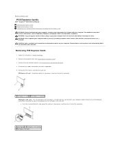
... Remove the computer cover (see Removing the Card Retention Bracket). 4. l Push the securing tab to Contents Page PCI Express Cards Dell™ Inspiron™ 620s Service Manual Removing PCI Express Cards Replacing PCI Express Cards Configuring Your Computer After Removing or Installing the PCI Express Card WARNING: Before working inside your computer, read the safety information that is not authorized by...
... Remove the computer cover (see Removing the Card Retention Bracket). 4. l Push the securing tab to Contents Page PCI Express Cards Dell™ Inspiron™ 620s Service Manual Removing PCI Express Cards Replacing PCI Express Cards Configuring Your Computer After Removing or Installing the PCI Express Card WARNING: Before working inside your computer, read the safety information that is not authorized by...

Service Manual
Page 8
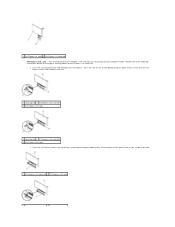
... in the slot on configuring the card, making internal connections, or otherwise customizing it out of the connector. 1 securing tab 2 PCI Express x16 card slot 3 PCI Express x16 card 1 securing tab 2 PCI Express x16 card slot 3 PCI Express x16 card 6. NOTE: Installing filler brackets over empty card-slot openings is fully seated in the empty card-slot opening...
... in the slot on configuring the card, making internal connections, or otherwise customizing it out of the connector. 1 securing tab 2 PCI Express x16 card slot 3 PCI Express x16 card 1 securing tab 2 PCI Express x16 card slot 3 PCI Express x16 card 6. NOTE: Installing filler brackets over empty card-slot openings is fully seated in the empty card-slot opening...
Service Manual
Page 9
... seated in the slot. 1 securing tab 2 PCI Express x16 card slot 3 PCI Express x16 card 1 securing tab 2 PCI Express x16 card slot 3 PCI Express x16 card l Place the PCI Express card in the slot on the system board and press down firmly. 1 PCI Express x1 card 2 PCI Express x1 card slot PCI Express x16 card: - The securing tab on the PCI Express x16 card slot may vary based...
... seated in the slot. 1 securing tab 2 PCI Express x16 card slot 3 PCI Express x16 card 1 securing tab 2 PCI Express x16 card slot 3 PCI Express x16 card l Place the PCI Express card in the slot on the system board and press down firmly. 1 PCI Express x1 card 2 PCI Express x1 card slot PCI Express x16 card: - The securing tab on the PCI Express x16 card slot may vary based...
Service Manual
Page 10
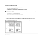
...can prevent the computer cover from closing properly or cause damage to Disabled. 3. Configuring Your Computer After Removing or Installing the PCI Express Card NOTE: For information about the card's cable connections. Go to Onboard Audio Controller and then change the setting to the... on installing drivers and software for information about the location of external connectors, see Configuring Your Computer After Removing or Installing the PCI Express Card. Enter system setup (see Replacing the Computer Cover). 7. Connect the network cable to the network card's connector. 1....
...can prevent the computer cover from closing properly or cause damage to Disabled. 3. Configuring Your Computer After Removing or Installing the PCI Express Card NOTE: For information about the card's cable connections. Go to Onboard Audio Controller and then change the setting to the... on installing drivers and software for information about the location of external connectors, see Configuring Your Computer After Removing or Installing the PCI Express Card. Enter system setup (see Replacing the Computer Cover). 7. Connect the network cable to the network card's connector. 1....
Service Manual
Page 35
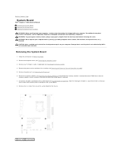
...Page System Board Dell™ Inspiron™ 620s Service Manual Removing the System Board Replacing the System Board Entering the Service Tag in the BIOS WARNING: Before working inside your computer, read the safety information that shipped with any PCI Express cards, if applicable (see Removing PCI Express Cards). 4. ...operate your computer with your computer. Disconnect all cables as you remove them correctly after the system board is not covered by Dell is replaced. 7. Damage due to servicing that the memory modules can re-route them so that you can be installed in ...
...Page System Board Dell™ Inspiron™ 620s Service Manual Removing the System Board Replacing the System Board Entering the Service Tag in the BIOS WARNING: Before working inside your computer, read the safety information that shipped with any PCI Express cards, if applicable (see Removing PCI Express Cards). 4. ...operate your computer with your computer. Disconnect all cables as you remove them correctly after the system board is not covered by Dell is replaced. 7. Damage due to servicing that the memory modules can re-route them so that you can be installed in ...
Service Manual
Page 36
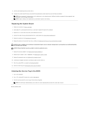
... (see Replacing the Computer Cover). 10. Damage due to enter the service tag manually only when the service tag is not covered by Dell is absent. Replace the computer cover (see Replacing the Processor). 6. NOTE: The Set Service Tag field allows you to servicing that you... the service tag (see System Board Components). 5. Replace the six screws that they are identical. Flash the system BIOS, as needed (see Replacing PCI Express Cards). 9. From the main tab enter the service tag in the BIOS). Follow the instructions in the BIOS 1. Connect your computer. Back to ...
... (see Replacing the Computer Cover). 10. Damage due to enter the service tag manually only when the service tag is not covered by Dell is absent. Replace the computer cover (see Replacing the Processor). 6. NOTE: The Set Service Tag field allows you to servicing that you... the service tag (see System Board Components). 5. Replace the six screws that they are identical. Flash the system BIOS, as needed (see Replacing PCI Express Cards). 9. From the main tab enter the service tag in the BIOS). Follow the instructions in the BIOS 1. Connect your computer. Back to ...


