Quick Reference Guide
Page 9
...computer problem based on the computer. For more information about sleep modes and exiting from a power-saving mode, press the power button or use . Instead, perform an operating system shutdown. To exit from a power-saving mode, see "Diagnostic Lights" on page 36 for devices that a LAN (network)...or DVD (if applicable) into this drive. NOTICE: To avoid losing data, do not turn on the diagnostic code. The computer is in a power-saving mode. • Blinking or solid amber - Use the headphone connector to indicate different operating states: • No light - Use the ...
...computer problem based on the computer. For more information about sleep modes and exiting from a power-saving mode, press the power button or use . Instead, perform an operating system shutdown. To exit from a power-saving mode, see "Diagnostic Lights" on page 36 for devices that a LAN (network)...or DVD (if applicable) into this drive. NOTICE: To avoid losing data, do not turn on the diagnostic code. The computer is in a power-saving mode. • Blinking or solid amber - Use the headphone connector to indicate different operating states: • No light - Use the ...
Quick Reference Guide
Page 11
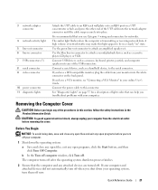
... help avoid damaging a computer with a manual voltage-selection switch, set to the 115-V position even though the AC power available in your location. 4 power connector Insert the power cable into this connector. 5 back-panel connectors Plug serial, USB, and other devices into either an auto-sensing voltage...Reference Guide 11 It is recommended that you to open the computer cover. 2 padlock ring Insert a padlock to operate with the AC power available in your location. 1 cover release latch This latch allows you use the back USB connectors for any installed PCI and PCI ...
... help avoid damaging a computer with a manual voltage-selection switch, set to the 115-V position even though the AC power available in your location. 4 power connector Insert the power cable into this connector. 5 back-panel connectors Plug serial, USB, and other devices into either an auto-sensing voltage...Reference Guide 11 It is recommended that you to open the computer cover. 2 padlock ring Insert a padlock to operate with the AC power available in your location. 1 cover release latch This latch allows you use the back USB connectors for any installed PCI and PCI ...
Quick Reference Guide
Page 12
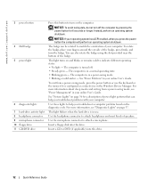
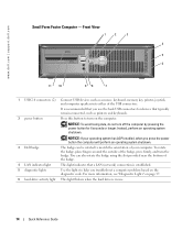
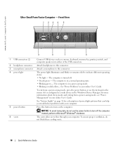
... mode, see "Diagnostic Lights" on and blinks or remains solid to indicate different operating states: • No light - www.dell.com | support.dell.com 3 power button 4 Dell badge 5 power light 6 diagnostic lights 7 hard-drive activity light 8 headphone connector 9 microphone connector 10 floppy drive 11 CD/DVD drive Press this button to turn on page ...
... mode, see "Diagnostic Lights" on and blinks or remains solid to indicate different operating states: • No light - www.dell.com | support.dell.com 3 power button 4 Dell badge 5 power light 6 diagnostic lights 7 hard-drive activity light 8 headphone connector 9 microphone connector 10 floppy drive 11 CD/DVD drive Press this button to turn on page ...
Quick Reference Guide
Page 13
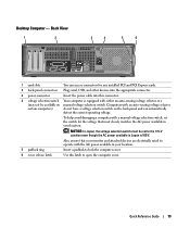
... any installed PCI and PCI Express cards. 2 back-panel connectors Plug serial, USB, and other devices into the appropriate connector. 3 power connector Insert the power cable into this latch to operate with either an auto-sensing voltage selector or a (may not be set to the 115-V position... even though the AC power available in your location. 5 padlock ring Insert a padlock to lock the computer cover. 6 cover release latch Use this connector. 4 voltage selection...
... any installed PCI and PCI Express cards. 2 back-panel connectors Plug serial, USB, and other devices into the appropriate connector. 3 power connector Insert the power cable into this latch to operate with either an auto-sensing voltage selector or a (may not be set to the 115-V position... even though the AC power available in your location. 5 padlock ring Insert a padlock to lock the computer cover. 6 cover release latch Use this connector. 4 voltage selection...
Quick Reference Guide
Page 14
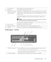
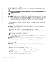
www.dell.com | support.dell.com Small Form Factor Computer - NOTICE: To avoid losing data, do not turn off the computer by pressing the power button for devices that a LAN (network) connection is in use the back USB connectors for 6 seconds or longer. To rotate the badge, ... operating system shutdown. Press this button to match the orientation of the USB connectors. 2 power button It is recommended that you press the power button the computer will perform an operating system shutdown. 3 Dell badge The badge can also rotate the badge using the slot provided near the bottom of ...
www.dell.com | support.dell.com Small Form Factor Computer - NOTICE: To avoid losing data, do not turn off the computer by pressing the power button for devices that a LAN (network) connection is in use the back USB connectors for 6 seconds or longer. To rotate the badge, ... operating system shutdown. Press this button to match the orientation of the USB connectors. 2 power button It is recommended that you press the power button the computer will perform an operating system shutdown. 3 Dell badge The badge can also rotate the badge using the slot provided near the bottom of ...
Quick Reference Guide
Page 15
...use the keyboard or the mouse if it is turned off. • Steady green - Insert a floppy disk into this drive. Connect the power cable to attach a microphone. Use the headphone connector to indicate different operating states: • No light - Plug serial, USB, and other...devices into the appropriate connector. Quick Reference Guide 15 The computer is configured as a wake device in your online User's Guide. 7 power light 8 headphone connector 9 microphone connector 10 floppy drive 11 CD/DVD drive Turns on page 36 for any installed PCI and PCI Express cards....
...use the keyboard or the mouse if it is turned off. • Steady green - Insert a floppy disk into this drive. Connect the power cable to attach a microphone. Use the headphone connector to indicate different operating states: • No light - Plug serial, USB, and other...devices into the appropriate connector. Quick Reference Guide 15 The computer is configured as a wake device in your online User's Guide. 7 power light 8 headphone connector 9 microphone connector 10 floppy drive 11 CD/DVD drive Turns on page 36 for any installed PCI and PCI Express cards....
Quick Reference Guide
Page 16
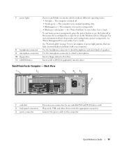
... | support.dell.com 4 voltage selection switch Your computer is equipped with a manual voltage-selection switch, set to the 115-V position even though the AC power available in Japan is 100 V. To help avoid damaging a computer with either an auto-sensing voltage selector or a (may not...1-Gbps (or 1000-Mbps) network and the computer. • Off - Mini Tower, Desktop, and Small Form Factor Computers - Computers with the AC power available in your location. 5 padlock ring Insert a padlock to lock the computer cover. 6 cover release latch Use this latch to the network. 16 ...
... | support.dell.com 4 voltage selection switch Your computer is equipped with a manual voltage-selection switch, set to the 115-V position even though the AC power available in Japan is 100 V. To help avoid damaging a computer with either an auto-sensing voltage selector or a (may not...1-Gbps (or 1000-Mbps) network and the computer. • Off - Mini Tower, Desktop, and Small Form Factor Computers - Computers with the AC power available in your location. 5 padlock ring Insert a padlock to lock the computer cover. 6 cover release latch Use this latch to the network. 16 ...
Quick Reference Guide
Page 18
...To ensure proper ventilation, do not use the keyboard or the mouse if it is in a power-saving mode. • Blinking or solid yellow- To exit from a power-saving mode, see "Power Management" in the Windows Device Manager. NOTICE: To avoid losing data, do not block these ...about sleep modes and exiting from a power-saving mode, press the power button or use the power button to turn off . • Steady green - Attach a microphone to flow through your computer. See "System Lights" on the computer. www.dell.com | support.dell.com Ultra-Small Form Factor Computer - ...
...To ensure proper ventilation, do not use the keyboard or the mouse if it is in a power-saving mode. • Blinking or solid yellow- To exit from a power-saving mode, see "Power Management" in the Windows Device Manager. NOTICE: To avoid losing data, do not block these ...about sleep modes and exiting from a power-saving mode, press the power button or use the power button to turn off . • Steady green - Attach a microphone to flow through your computer. See "System Lights" on the computer. www.dell.com | support.dell.com Ultra-Small Form Factor Computer - ...

Quick Reference Guide
Page 20
... a clockwise direction to the network or the network controller is not detecting a physical connection to remove the cover. www.dell.com | support.dell.com 1 diagnostic lights 2 computer cover release knob 3 back-panel connectors 4 power connector 5 vents Use the lights to this knob in system setup. 20 Quick Reference Guide For more information, see...
... a clockwise direction to the network or the network controller is not detecting a physical connection to remove the cover. www.dell.com | support.dell.com 1 diagnostic lights 2 computer cover release knob 3 back-panel connectors 4 power connector 5 vents Use the lights to this knob in system setup. 20 Quick Reference Guide For more information, see...
Quick Reference Guide
Page 21
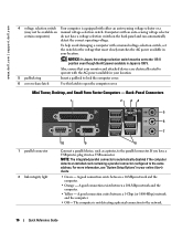
...Information Guide. Quick Reference Guide 21 3 network adapter connector 4 network activity light 5 line-out connector 6 line-in connector 7 USB connectors (5) 8 serial connector 9 video connector 10 power connector 11 diagnostic lights Attach the UTP cable to an RJ45 jack wall plate or to an RJ45 port on a UTP concentrator or hub, and... data, save and close any open programs before removing the cover. A high volume of the procedures in a steady "on the back panel. Connect the power cable to attach an amplified speaker set. It is transmitting or receiving network data.
...Information Guide. Quick Reference Guide 21 3 network adapter connector 4 network activity light 5 line-out connector 6 line-in connector 7 USB connectors (5) 8 serial connector 9 video connector 10 power connector 11 diagnostic lights Attach the UTP cable to an RJ45 jack wall plate or to an RJ45 port on a UTP concentrator or hub, and... data, save and close any open programs before removing the cover. A high volume of the procedures in a steady "on the back panel. Connect the power cable to attach an amplified speaker set. It is transmitting or receiving network data.
Quick Reference Guide
Page 22
... surface to avoid bending any telephone or telecommunication lines from the computer. 3 Disconnect your computer if it is attached. www.dell.com | support.dell.com Before Working Inside Your Computer Use the following illustration. 4 Slide the cover release latch back as you lift the cover...Mini Tower Computer NOTICE: Before touching anything inside your computer, ground yourself by Dell is not already turned off your computer and all attached devices from their electrical outlets, and then press the power button to help ensure your computer. As you disconnect the cable. Also,...
... surface to avoid bending any telephone or telecommunication lines from the computer. 3 Disconnect your computer if it is attached. www.dell.com | support.dell.com Before Working Inside Your Computer Use the following illustration. 4 Slide the cover release latch back as you lift the cover...Mini Tower Computer NOTICE: Before touching anything inside your computer, ground yourself by Dell is not already turned off your computer and all attached devices from their electrical outlets, and then press the power button to help ensure your computer. As you disconnect the cable. Also,...
Quick Reference Guide
Page 28
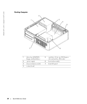
www.dell.com | support.dell.com Desktop Computer 2 1 3 4 5 7 6 1 drives bay (CD/DVD, floppy, and hard drive) 2 power supply 3 chassis intrusion switch 4 system board 5 card slots (3) for one PCI Express x16 card and two PCI cards 6 heat sink assembly 7 front I/O panel 28 Quick Reference Guide
www.dell.com | support.dell.com Desktop Computer 2 1 3 4 5 7 6 1 drives bay (CD/DVD, floppy, and hard drive) 2 power supply 3 chassis intrusion switch 4 system board 5 card slots (3) for one PCI Express x16 card and two PCI cards 6 heat sink assembly 7 front I/O panel 28 Quick Reference Guide
Quick Reference Guide
Page 29
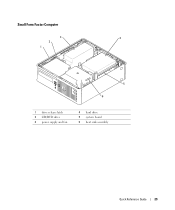
Small Form Factor Computer 3 4 2 1 5 6 1 drive release latch 2 CD/DVD drive 3 power supply and fan 4 hard drive 5 system board 6 heat sink assembly Quick Reference Guide 29
Small Form Factor Computer 3 4 2 1 5 6 1 drive release latch 2 CD/DVD drive 3 power supply and fan 4 hard drive 5 system board 6 heat sink assembly Quick Reference Guide 29
Quick Reference Guide
Page 31
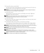
...monitors have an optional modem, connect the telephone line to the modem. NOTE: Before you have the video connector underneath the back of the power cables to the network adapter. 3 Connect the monitor. NOTE: Your computer may vary slightly from telephone communications can cause damage to electrical outlets...switch must be set the switch for the voltage that the device or software is set to verify that most closely matches the AC power available in Japan is 100 V. Quick Reference Guide 31 NOTICE: To help avoid damaging a computer with your monitor for your location....
...monitors have an optional modem, connect the telephone line to the modem. NOTE: Before you have the video connector underneath the back of the power cables to the network adapter. 3 Connect the monitor. NOTE: Your computer may vary slightly from telephone communications can cause damage to electrical outlets...switch must be set the switch for the voltage that the device or software is set to verify that most closely matches the AC power available in Japan is 100 V. Quick Reference Guide 31 NOTICE: To help avoid damaging a computer with your monitor for your location....

Quick Reference Guide
Page 33
...perform as your computer. Power Connections Solving Problems Dell provides a number of tools to Use the Dell Diagnostics If you contact Dell for your computer, see the Dell Support website at support.dell.com. record your online User's Guide. and then contact Dell from Dell, write a detailed description ... Service Code and Service Tag. For the latest troubleshooting information available for technical assistance. See "Finding Information" on contacting Dell, see your Express Service Code and Service Tag below; For information on page 5 for an example of your online User's...
...perform as your computer. Power Connections Solving Problems Dell provides a number of tools to Use the Dell Diagnostics If you contact Dell for your computer, see the Dell Support website at support.dell.com. record your online User's Guide. and then contact Dell from Dell, write a detailed description ... Service Code and Service Tag. For the latest troubleshooting information available for technical assistance. See "Finding Information" on contacting Dell, see your Express Service Code and Service Tag below; For information on page 5 for an example of your online User's...
Quick Reference Guide
Page 36
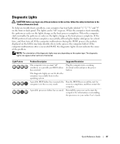
..."Diagnostic Lights" on page 37 to see your online User's Guide. No corrective action is identified. Press the power button, move the mouse, or press a key on contacting Dell, see if light, no beep code but the computer locks up during POST A problem was detected while the ...installed. Also, check "Diagnostic Lights" on page 37 to the Main Menu screen. If the Dell Diagnostics is identified. Blinking yellow A power supply or system board failure has occurred. www.dell.com | support.dell.com 5 Close the test screen to return to see your online User's Guide. To exit the...
..."Diagnostic Lights" on page 37 to see your online User's Guide. No corrective action is identified. Press the power button, move the mouse, or press a key on contacting Dell, see if light, no beep code but the computer locks up during POST A problem was detected while the ...installed. Also, check "Diagnostic Lights" on page 37 to the Main Menu screen. If the Dell Diagnostics is identified. Blinking yellow A power supply or system board failure has occurred. www.dell.com | support.dell.com 5 Close the test screen to return to see your online User's Guide. To exit the...
Quick Reference Guide
Page 37
If the computer malfunctions after the computer successfully boots to the operating system. Plug the computer into a working electrical outlet and press the power button. For information on reinstalling the processor, see your computer has four lights labeled "1," "2," "3," and "4" on the front or back panel. Quick Reference Guide 37 ...
If the computer malfunctions after the computer successfully boots to the operating system. Plug the computer into a working electrical outlet and press the power button. For information on reinstalling the processor, see your computer has four lights labeled "1," "2," "3," and "4" on the front or back panel. Quick Reference Guide 37 ...

Quick Reference Guide
Page 38
... starts normally, reinstall an additional module. Reinstall all power and data cables and occurred. Continue until you have one module, and then restart the computer. For information on reinstalling memory modules, see your online User's Guide. restart the computer. www.dell.com | support.dell.com Light Pattern Problem Description Suggested Resolution Memory modules...
... starts normally, reinstall an additional module. Reinstall all power and data cables and occurred. Continue until you have one module, and then restart the computer. For information on reinstalling memory modules, see your online User's Guide. restart the computer. www.dell.com | support.dell.com Light Pattern Problem Description Suggested Resolution Memory modules...

Quick Reference Guide
Page 40
..., a burst of -day clock stopped Cause Slave interrupt mask register failure Interrupt vector loading failure Keyboard Controller test failure NVRAM power loss Invalid NVRAM configuration Video Memory test failure Screen initialization failure Screen retrace failure Search for video ROM failure No timer tick ...Shutdown failure Serial or parallel port test failure Failure to decompress code to identify a more serious cause. 3 Contact Dell for technical assistance. This beep code tells you that the computer encountered a memory problem. If your computer beeps during start -...
..., a burst of -day clock stopped Cause Slave interrupt mask register failure Interrupt vector loading failure Keyboard Controller test failure NVRAM power loss Invalid NVRAM configuration Video Memory test failure Screen initialization failure Screen retrace failure Search for video ROM failure No timer tick ...Shutdown failure Serial or parallel port test failure Failure to decompress code to identify a more serious cause. 3 Contact Dell for technical assistance. This beep code tells you that the computer encountered a memory problem. If your computer beeps during start -...

Quick Reference Guide
Page 47
... labels Microsoft Windows, 6 Service Tag, 6 M Microsoft Windows label, 6 E error messages beep codes, 40 H hardware beep codes, 40 conflicts, 41 Dell Diagnostics, 33 Hardware Troubleshooter, 41 Help and Support Center, 7 I installing parts before you begin, 21 IRQ conflicts, 41 O operating system CD, 7 ...Installation Guide, 7 reinstalling Windows XP, 43 Operating System CD, 7 P power light diagnosing problems with, 36 locations, 9, 12, 15, 18 problems beep codes, 40 conflicts, 41 Dell Diagnostics, 33 restore computer to previous operating state, 41 Index 47
... labels Microsoft Windows, 6 Service Tag, 6 M Microsoft Windows label, 6 E error messages beep codes, 40 H hardware beep codes, 40 conflicts, 41 Dell Diagnostics, 33 Hardware Troubleshooter, 41 Help and Support Center, 7 I installing parts before you begin, 21 IRQ conflicts, 41 O operating system CD, 7 ...Installation Guide, 7 reinstalling Windows XP, 43 Operating System CD, 7 P power light diagnosing problems with, 36 locations, 9, 12, 15, 18 problems beep codes, 40 conflicts, 41 Dell Diagnostics, 33 restore computer to previous operating state, 41 Index 47


