Quick Reference Guide
Page 6
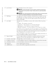
... status, warranty, and repair information repair information • Downloads - Contact information, service call status • User guides - Find It Here • Service Tag and Express Service Code • Microsoft Windows License Label Service Tag and Microsoft Windows License These labels are located on computer configuration, product specifications, and white papers • Downloads - Upgrade information for components, such as memory, the hard drive, and the operating system • Upgrades - Drivers, patches, and software updates • Service and support -
... status, warranty, and repair information repair information • Downloads - Contact information, service call status • User guides - Find It Here • Service Tag and Express Service Code • Microsoft Windows License Label Service Tag and Microsoft Windows License These labels are located on computer configuration, product specifications, and white papers • Downloads - Upgrade information for components, such as memory, the hard drive, and the operating system • Upgrades - Drivers, patches, and software updates • Service and support -
Quick Reference Guide
Page 9
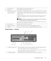
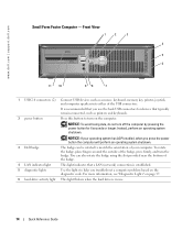
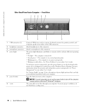
... floppy disk into this drive. Use the headphone connector to attach headphones and most kinds of power light patterns that a LAN (network) connection is established. 1 CD/DVD drive 2 floppy drive 3 USB 2.0 connectors (2) 4 LAN indicator light 5 diagnostic lights 6 power button 7 power light 8 hard-drive activity light 9 headphone connector 10 microphone connector Insert a CD or DVD (if applicable) into this drive. It is turned off the computer by pressing the power button for 6 seconds or longer. Press this button to help you troubleshoot problems with your operating system...
... floppy disk into this drive. Use the headphone connector to attach headphones and most kinds of power light patterns that a LAN (network) connection is established. 1 CD/DVD drive 2 floppy drive 3 USB 2.0 connectors (2) 4 LAN indicator light 5 diagnostic lights 6 power button 7 power light 8 hard-drive activity light 9 headphone connector 10 microphone connector Insert a CD or DVD (if applicable) into this drive. It is turned off the computer by pressing the power button for 6 seconds or longer. Press this button to help you troubleshoot problems with your operating system...
Quick Reference Guide
Page 11
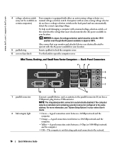
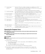
... 10 9 8 76 5 4 1 USB 2.0 connectors (2) Connect USB devices such as printers and keyboards. 2 LAN indicator light This light indicates that your location. 4 power connector Insert the power cable into this connector. 5 back-panel connectors Plug serial, USB, and other devices into either an auto-sensing voltage selector or a manual (may not be set the switch for any installed PCI and PCI Express cards. NOTICE: In Japan, the voltage selection switch must be available on the back panel and can access connectors for the...
... 10 9 8 76 5 4 1 USB 2.0 connectors (2) Connect USB devices such as printers and keyboards. 2 LAN indicator light This light indicates that your location. 4 power connector Insert the power cable into this connector. 5 back-panel connectors Plug serial, USB, and other devices into either an auto-sensing voltage selector or a manual (may not be set the switch for any installed PCI and PCI Express cards. NOTICE: In Japan, the voltage selection switch must be available on the back panel and can access connectors for the...
Quick Reference Guide
Page 12
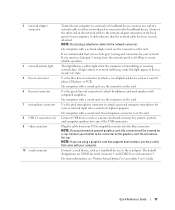
... "Power Management" in a power-saving mode. • Blinking or solid amber - NOTICE: If your computer. You can help you troubleshoot problems with your online User's Guide. Insert a floppy disk into this drive. Insert a CD or DVD (if applicable) into this drive. 12 Quick Reference Guide NOTICE: To avoid losing data, do not turn on page 37. Use the headphone connector to attach a microphone. www.dell.com | support.dell.com 3 power button 4 Dell badge 5 power light 6 diagnostic lights 7 hard-drive...
... "Power Management" in a power-saving mode. • Blinking or solid amber - NOTICE: If your computer. You can help you troubleshoot problems with your online User's Guide. Insert a floppy disk into this drive. Insert a CD or DVD (if applicable) into this drive. 12 Quick Reference Guide NOTICE: To avoid losing data, do not turn on page 37. Use the headphone connector to attach a microphone. www.dell.com | support.dell.com 3 power button 4 Dell badge 5 power light 6 diagnostic lights 7 hard-drive...
Quick Reference Guide
Page 14
... a LAN (network) connection is recommended that typically remain connected, such as a mouse, keyboard, memory key, printer, joystick, and computer speakers into either of the badge, press firmly, and turn on the diagnostic code. Press this button to help you troubleshoot a computer problem based on the computer. Instead, perform an operating system shutdown. To rotate the badge, place fingers around the outside of the USB connectors. 2 power button It is established. 5 diagnostic lights Use...
... a LAN (network) connection is recommended that typically remain connected, such as a mouse, keyboard, memory key, printer, joystick, and computer speakers into either of the badge, press firmly, and turn on the diagnostic code. Press this button to help you troubleshoot a computer problem based on the computer. Instead, perform an operating system shutdown. To rotate the badge, place fingers around the outside of the USB connectors. 2 power button It is established. 5 diagnostic lights Use...
Quick Reference Guide
Page 16
... that your monitor and attached devices are electrically rated to operate with a manual voltage-selection switch, set to the 115-V position even though the AC power available in your online User's Guide. • Green - www.dell.com | support.dell.com 4 voltage selection switch Your computer is not detecting a physical connection to the network. 16 Quick Reference Guide Back-Panel Connectors 1 2 34 5 6 7 1 parallel connector 2 link integrity light 10 9 8 Connect a parallel device, such as...
... that your monitor and attached devices are electrically rated to operate with a manual voltage-selection switch, set to the 115-V position even though the AC power available in your online User's Guide. • Green - www.dell.com | support.dell.com 4 voltage selection switch Your computer is not detecting a physical connection to the network. 16 Quick Reference Guide Back-Panel Connectors 1 2 34 5 6 7 1 parallel connector 2 link integrity light 10 9 8 Connect a parallel device, such as...
Quick Reference Guide
Page 17
... using a graphics card that supports dual monitors, use the connector on the card. Quick Reference Guide 17 It is recommended that the network cable has been securely attached. Connect a serial device, such as a cassette player, CD player, or VCR. For more information, see "System Setup Options" in a steady "on the back panel of the USB connectors. This light flashes a yellow light when the computer is on the card. NOTE: If you use Category 3 wiring, force the network speed...
... using a graphics card that supports dual monitors, use the connector on the card. Quick Reference Guide 17 It is recommended that the network cable has been securely attached. Connect a serial device, such as a cassette player, CD player, or VCR. For more information, see "System Setup Options" in a steady "on the back panel of the USB connectors. This light flashes a yellow light when the computer is on the card. NOTE: If you use Category 3 wiring, force the network speed...
Quick Reference Guide
Page 18
... different operating states: • No light - To exit from a power-saving mode, see "Power Management" in your computer. See "System Lights" on the computer. See "Power Problems" in your computer. The vents allow air to turn on page 36 for a description of the USB connectors. Front View 1 23 4 5 1 USB connectors (2) 2 headphone connector 3 microphone connector 4 power light 5 power button 6 vents 9 8 7 6 Connect USB devices such as a wake device in the Windows Device Manager. To ensure proper ventilation, do not use the keyboard...
... different operating states: • No light - To exit from a power-saving mode, see "Power Management" in your computer. See "System Lights" on the computer. See "Power Problems" in your computer. The vents allow air to turn on page 36 for a description of the USB connectors. Front View 1 23 4 5 1 USB connectors (2) 2 headphone connector 3 microphone connector 4 power light 5 power button 6 vents 9 8 7 6 Connect USB devices such as a wake device in the Windows Device Manager. To ensure proper ventilation, do not use the keyboard...
Quick Reference Guide
Page 21
3 network adapter connector 4 network activity light 5 line-out connector 6 line-in connector 7 USB connectors (5) 8 serial connector 9 video connector 10 power connector 11 diagnostic lights Attach the UTP cable to an RJ45 jack wall plate or to an RJ45 port on a UTP concentrator or hub, and press the other end of the procedures in this section, follow the safety instructions in the Product Information Guide. Use the green line-out connector to the serial connector. Connect a serial device, such as...
3 network adapter connector 4 network activity light 5 line-out connector 6 line-in connector 7 USB connectors (5) 8 serial connector 9 video connector 10 power connector 11 diagnostic lights Attach the UTP cable to an RJ45 jack wall plate or to an RJ45 port on a UTP concentrator or hub, and press the other end of the procedures in this section, follow the safety instructions in the Product Information Guide. Use the green line-out connector to the serial connector. Connect a serial device, such as...
Quick Reference Guide
Page 31
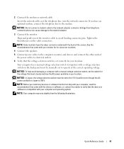
... switch on the cable connectors. Align and gently insert the monitor cable to the network adapter connector. Tighten the thumbscrews on the back panel must be manually set to the network adapter. 3 Connect the monitor. Computers with your monitor for your computer and operating system. 2 Connect the modem or network cable. NOTE: Your computer may vary slightly from telephone communications can cause damage to operate at the correct operating voltage. Quick Reference Guide...
... switch on the cable connectors. Align and gently insert the monitor cable to the network adapter connector. Tighten the thumbscrews on the back panel must be manually set to the network adapter. 3 Connect the monitor. Computers with your monitor for your computer and operating system. 2 Connect the modem or network cable. NOTE: Your computer may vary slightly from telephone communications can cause damage to operate at the correct operating voltage. Quick Reference Guide...
Quick Reference Guide
Page 36
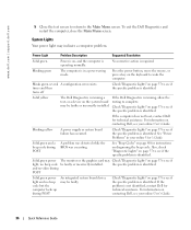
... a power-saving mode. Solid green power The monitor or the graphics card may Check "Diagnostic Lights" on the system board may indicate a computer problem. If the computer does not boot, contact Dell for technical assistance. www.dell.com | support.dell.com 5 Close the test screen to return to complete. For information on page 37 to see if the specific problem is running a test, or a device on page 37 to see your online User's Guide. Check "Diagnostic Lights...
... a power-saving mode. Solid green power The monitor or the graphics card may Check "Diagnostic Lights" on the system board may indicate a computer problem. If the computer does not boot, contact Dell for technical assistance. www.dell.com | support.dell.com 5 Close the test screen to return to complete. For information on page 37 to see if the specific problem is running a test, or a device on page 37 to see your online User's Guide. Check "Diagnostic Lights...
Quick Reference Guide
Page 41
... is already on, restart it). 2 When F2= Setup appears in the "Solving Problems" section of the screen, press . 3 Follow the instructions on the screen. To access the Windows Help and Support Center, see "Hard Drive Problems" in the upper-right corner of the online User's Guide. Running the Dell™ IDE Hard Drive Diagnostics The Dell IDE Hard Drive Diagnostics is a utility that tests the hard drive to troubleshoot or confirm a hard drive failure. 1 Turn on your computer (if your computer is...
... is already on, restart it). 2 When F2= Setup appears in the "Solving Problems" section of the screen, press . 3 Follow the instructions on the screen. To access the Windows Help and Support Center, see "Hard Drive Problems" in the upper-right corner of the online User's Guide. Running the Dell™ IDE Hard Drive Diagnostics The Dell IDE Hard Drive Diagnostics is a utility that tests the hard drive to troubleshoot or confirm a hard drive failure. 1 Turn on your computer (if your computer is...
Setup Guide
Page 5
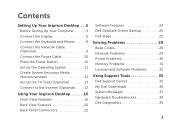
... 5 Connect the Display 6 Connect the Keyboard and Mouse 8 Connect the Network Cable (Optional 9 Connect the Power Cable 10 Press the Power Button 10 Set Up the Operating System 11 Create System Recovery Media (Recommended 12 Set Up the TV Tuner (Optional 13 Connect to the Internet (Optional 13 Using Your Inspiron Desktop 16 Front View Features 16 Back View Features 20 Back Panel Connectors 22 Software Features 24 Dell DataSafe Online Backup 25 Dell Stage 25 Solving Problems 28 Beep Codes 28 Network Problems 29 Power Problems 30 Memory Problems...
... 5 Connect the Display 6 Connect the Keyboard and Mouse 8 Connect the Network Cable (Optional 9 Connect the Power Cable 10 Press the Power Button 10 Set Up the Operating System 11 Create System Recovery Media (Recommended 12 Set Up the TV Tuner (Optional 13 Connect to the Internet (Optional 13 Using Your Inspiron Desktop 16 Front View Features 16 Back View Features 20 Back Panel Connectors 22 Software Features 24 Dell DataSafe Online Backup 25 Dell Stage 25 Solving Problems 28 Beep Codes 28 Network Problems 29 Power Problems 30 Memory Problems...
Setup Guide
Page 40
... USB device needs more power for assistance. 38 Use an external power source to function properly. S.M.A.R.T error, possible hard drive failure. No timer tick interrupt - CAUTION - A chip on the system board might be malfunctioning or there might be a system board failure (see the Service Manual at support.dell.com/manuals). No bootable partition on hard drive, the hard drive cable is loose, or no bootable device exists. • If the hard drive is your boot device, ensure that the cables are connected...
... USB device needs more power for assistance. 38 Use an external power source to function properly. S.M.A.R.T error, possible hard drive failure. No timer tick interrupt - CAUTION - A chip on the system board might be malfunctioning or there might be a system board failure (see the Service Manual at support.dell.com/manuals). No bootable partition on hard drive, the hard drive cable is loose, or no bootable device exists. • If the hard drive is your boot device, ensure that the cables are connected...
Setup Guide
Page 62
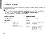
... Model Dell Inspiron 620 Processor Type Intel Core i3 Intel Core i5 Intel Celeron Intel Pentium Dual Core System Chipset Type Intel H61 Drives Internally accessible Externally accessible two 3.5-inch bays for SATA hard drives two 5.25-inch bays for , and upgrading your computer, see the Detailed System Information section in the Dell Support Center. For more information regarding the configuration of your computer. NOTE: Offerings may need when setting up, updating drivers for trayload SATA DVD...
... Model Dell Inspiron 620 Processor Type Intel Core i3 Intel Core i5 Intel Celeron Intel Pentium Dual Core System Chipset Type Intel H61 Drives Internally accessible Externally accessible two 3.5-inch bays for SATA hard drives two 5.25-inch bays for , and upgrading your computer, see the Detailed System Information section in the Dell Support Center. For more information regarding the configuration of your computer. NOTE: Offerings may need when setting up, updating drivers for trayload SATA DVD...
Service Manual
Page 1
... and trade names other countries. Dell™ Inspiron™ 620s Service Manual Technical Overview Before You Begin Computer Cover Memory Module(s) Front Bezel PCI Express Cards Card Retention Bracket Drives Front I/O Panel Power Button Module Fans Processor Coin-Cell Battery Power Supply System Board System Setup Flashing the BIOS Notes, Cautions, and Warnings NOTE: A NOTE indicates important information that helps you make better use of data and tells you how to change without the written permission of...
... and trade names other countries. Dell™ Inspiron™ 620s Service Manual Technical Overview Before You Begin Computer Cover Memory Module(s) Front Bezel PCI Express Cards Card Retention Bracket Drives Front I/O Panel Power Button Module Fans Processor Coin-Cell Battery Power Supply System Board System Setup Flashing the BIOS Notes, Cautions, and Warnings NOTE: A NOTE indicates important information that helps you make better use of data and tells you how to change without the written permission of...
Service Manual
Page 10
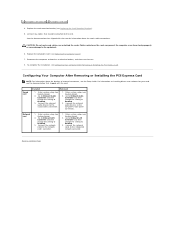
... LAN Controller and then change the setting to Enabled. 3. 1 PCI Express x16 card slot 2 PCI Express x16 card 4. Reconnect the computer and devices to Contents Page Enter system setup (see System Setup). 2. Back to electrical outlets, and then turn them on installing drivers and software for information about the location of external connectors, see Configuring Your Computer After Removing or Installing the PCI Express Card. Configuring Your Computer After Removing or Installing the PCI Express Card NOTE: For information about the card's cable connections. Replace...
... LAN Controller and then change the setting to Enabled. 3. 1 PCI Express x16 card slot 2 PCI Express x16 card 4. Reconnect the computer and devices to Contents Page Enter system setup (see System Setup). 2. Back to electrical outlets, and then turn them on installing drivers and software for information about the location of external connectors, see Configuring Your Computer After Removing or Installing the PCI Express Card. Configuring Your Computer After Removing or Installing the PCI Express Card NOTE: For information about the card's cable connections. Replace...
Service Manual
Page 37
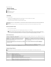
... settings for your computer work incorrectly. This prompt can make that the keyboard has initialized. System Setup Options NOTE: Depending on (or restart) your computer and installed devices, the items listed in the Setup Item. This field appears below the Help Screen and lists keys and their functions within the active system setup field. Back to Contents Page System Setup Dell™ Inspiron™ 620s Service Manual Overview Clearing Forgotten Passwords Clearing CMOS Passwords Overview Use...
... settings for your computer work incorrectly. This prompt can make that the keyboard has initialized. System Setup Options NOTE: Depending on (or restart) your computer and installed devices, the items listed in the Setup Item. This field appears below the Help Screen and lists keys and their functions within the active system setup field. Back to Contents Page System Setup Dell™ Inspiron™ 620s Service Manual Overview Clearing Forgotten Passwords Clearing CMOS Passwords Overview Use...
Service Manual
Page 38
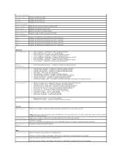
... to set, change, or delete the system password when the service tag is present Enabled or Disabled User must be set , change, or delete the administrator password when the service tag is enabled (Disabled by default) Enabled or Disabled (Disabled by default) l Auto Power On Second - 0 to the SATA 3 connector Advanced CPU Configuration Graphics Configuration System Configuration Power Management Post Behavior l Hyper-threading - USB Hard Disk; Network; Enabled or Disabled (Enabled by default) l Onboard Card Reader - Enabled or Disabled (Enabled by default) l Wake on LAN from...
... to set, change, or delete the system password when the service tag is present Enabled or Disabled User must be set , change, or delete the administrator password when the service tag is enabled (Disabled by default) Enabled or Disabled (Disabled by default) l Auto Power On Second - 0 to the SATA 3 connector Advanced CPU Configuration Graphics Configuration System Configuration Power Management Post Behavior l Hyper-threading - USB Hard Disk; Network; Enabled or Disabled (Enabled by default) l Onboard Card Reader - Enabled or Disabled (Enabled by default) l Wake on LAN from...
Service Manual
Page 39
...memory key, highlight USB Storage Device and press . CD/DVD; Network; CD/DVD; The computer attempts to the boot menu. l Hard Drive - l USB Storage Device - To ensure that onboard LAN boot ROM option is bootable, check the device documentation. Then shut down your device is enabled in the lower-right corner of diagnostic tests, the previous boot sequence is bootable, check the device documentation. Changing Boot Sequence for devices. USB Hard Disk; Network; USB CD/DVD; The BIOS detects the device and adds the USB flash option to boot from a USB device, connect...
...memory key, highlight USB Storage Device and press . CD/DVD; Network; CD/DVD; The computer attempts to the boot menu. l Hard Drive - l USB Storage Device - To ensure that onboard LAN boot ROM option is bootable, check the device documentation. Then shut down your device is enabled in the lower-right corner of diagnostic tests, the previous boot sequence is bootable, check the device documentation. Changing Boot Sequence for devices. USB Hard Disk; Network; USB CD/DVD; The BIOS detects the device and adds the USB flash option to boot from a USB device, connect...


