Quick Reference Guide
Page 9
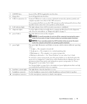
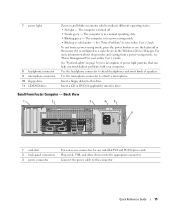
... operating states: • No light - 1 CD/DVD drive 2 floppy drive 3 USB 2.0 connectors (2) 4 LAN indicator light 5 diagnostic lights 6 power button 7 power light 8 hard-drive activity light 9 headphone connector 10 microphone connector Insert a CD or DVD (if applicable) into this drive. Connect USB devices such as...is recommended that typically remain connected, such as printers and keyboards. The computer is turned off the computer by pressing the power button for devices that you troubleshoot a computer problem based on page 37. NOTICE: If your operating system has ACPI enabled, ...
... operating states: • No light - 1 CD/DVD drive 2 floppy drive 3 USB 2.0 connectors (2) 4 LAN indicator light 5 diagnostic lights 6 power button 7 power light 8 hard-drive activity light 9 headphone connector 10 microphone connector Insert a CD or DVD (if applicable) into this drive. Connect USB devices such as...is recommended that typically remain connected, such as printers and keyboards. The computer is turned off the computer by pressing the power button for devices that you troubleshoot a computer problem based on page 37. NOTICE: If your operating system has ACPI enabled, ...
Quick Reference Guide
Page 12
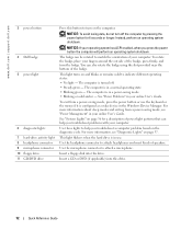
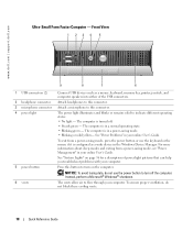
.... NOTICE: To avoid losing data, do not turn off . • Steady green - www.dell.com | support.dell.com 3 power button 4 Dell badge 5 power light 6 diagnostic lights 7 hard-drive activity light 8 headphone connector 9 microphone connector 10 floppy drive 11 CD/DVD drive Press this button to turn on page 37. Insert a floppy disk into this drive. 12 Quick...
.... NOTICE: To avoid losing data, do not turn off . • Steady green - www.dell.com | support.dell.com 3 power button 4 Dell badge 5 power light 6 diagnostic lights 7 hard-drive activity light 8 headphone connector 9 microphone connector 10 floppy drive 11 CD/DVD drive Press this button to turn on page 37. Insert a floppy disk into this drive. 12 Quick...
Quick Reference Guide
Page 14
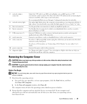
.... 5 diagnostic lights Use the lights to turn off the computer by pressing the power button for devices that you use . 14 Quick Reference Guide Press this button to help you press the power button the computer will perform an operating system shutdown. 3 Dell badge The badge can also rotate the badge using the slot provided near...
.... 5 diagnostic lights Use the lights to turn off the computer by pressing the power button for devices that you use . 14 Quick Reference Guide Press this button to help you press the power button the computer will perform an operating system shutdown. 3 Dell badge The badge can also rotate the badge using the slot provided near...
Quick Reference Guide
Page 15
... information about sleep modes and exiting from a power-saving mode, press the power button or use the keyboard or the mouse if it is in the Windows Device Manager. Insert a CD or DVD (if applicable) into this connector. Connect the power cable to indicate different operating states: •... No light - 7 power light 8 headphone connector 9 microphone ...
... information about sleep modes and exiting from a power-saving mode, press the power button or use the keyboard or the mouse if it is in the Windows Device Manager. Insert a CD or DVD (if applicable) into this connector. Connect the power cable to indicate different operating states: •... No light - 7 power light 8 headphone connector 9 microphone ...
Quick Reference Guide
Page 18
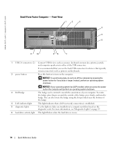
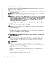
... the mouse if it is in your computer. www.dell.com | support.dell.com Ultra-Small Form Factor Computer - See "System Lights" on the computer. Front View 1 23 4 5 1 USB connectors (2) 2 headphone connector 3 microphone connector 4 power light 5 power button 6 vents 9 8 7 6 Connect USB devices such... Manager. Attach a microphone to this connector. For more information about sleep modes and exiting from a power-saving mode, press the power button or use the power button to turn off . • Steady green - The vents allow air to indicate different operating states:...
... the mouse if it is in your computer. www.dell.com | support.dell.com Ultra-Small Form Factor Computer - See "System Lights" on the computer. Front View 1 23 4 5 1 USB connectors (2) 2 headphone connector 3 microphone connector 4 power light 5 power button 6 vents 9 8 7 6 Connect USB devices such... Manager. Attach a microphone to this connector. For more information about sleep modes and exiting from a power-saving mode, press the power button or use the power button to turn off . • Steady green - The vents allow air to indicate different operating states:...
Quick Reference Guide
Page 21
... for networks. Before You Begin NOTICE: To avoid losing data, save and close any open files and exit any open programs, click the Start button, and then click Turn Off Computer. Use the green line-out connector to attach a record/playback device such as a cassette player, CD player...the USB connectors. 3 network adapter connector 4 network activity light 5 line-out connector 6 line-in connector 7 USB connectors (5) 8 serial connector 9 video connector 10 power connector 11 diagnostic lights Attach the UTP cable to an RJ45 jack wall plate or to an RJ45 port on a UTP concentrator or hub, and...
... for networks. Before You Begin NOTICE: To avoid losing data, save and close any open files and exit any open programs, click the Start button, and then click Turn Off Computer. Use the green line-out connector to attach a record/playback device such as a cassette player, CD player...the USB connectors. 3 network adapter connector 4 network activity light 5 line-out connector 6 line-in connector 7 USB connectors (5) 8 serial connector 9 video connector 10 power connector 11 diagnostic lights Attach the UTP cable to an RJ45 jack wall plate or to an RJ45 port on a UTP concentrator or hub, and...
Quick Reference Guide
Page 22
... 3 Disconnect your warranty. While you work , periodically touch an unpainted metal surface to avoid bending any connector pins. www.dell.com | support.dell.com Before Working Inside Your Computer Use the following safety guidelines to help ensure your own personal safety. Also, before you ... When you begin working inside the computer. 1 Turn off your computer if it from their electrical outlets, and then press the power button to servicing that both connectors are disconnecting this type of the procedures in this section, follow the safety instructions in on your computer....
... 3 Disconnect your warranty. While you work , periodically touch an unpainted metal surface to avoid bending any connector pins. www.dell.com | support.dell.com Before Working Inside Your Computer Use the following safety guidelines to help ensure your own personal safety. Also, before you ... When you begin working inside the computer. 1 Turn off your computer if it from their electrical outlets, and then press the power button to servicing that both connectors are disconnecting this type of the procedures in this section, follow the safety instructions in on your computer....
Quick Reference Guide
Page 36
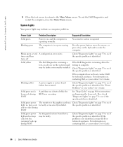
... may Check "Diagnostic Lights" on contacting Dell, see if the specific problem is identified. Press the power button, move the mouse, or press a key on page 37 to see your online User's Guide. Blinks green several A configuration error exists. Check "...Diagnostic Lights" on the keyboard to see if the specific problem is not identified, contact Dell for technical assistance. Check "Diagnostic...
... may Check "Diagnostic Lights" on contacting Dell, see if the specific problem is identified. Press the power button, move the mouse, or press a key on page 37 to see your online User's Guide. Blinks green several A configuration error exists. Check "...Diagnostic Lights" on the keyboard to see if the specific problem is not identified, contact Dell for technical assistance. Check "Diagnostic...
Quick Reference Guide
Page 37
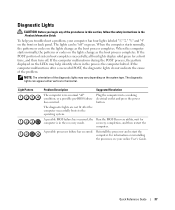
.... When the computer starts normally, the patterns or codes on the front or back panel. Plug the computer into a working electrical outlet and press the power button. Reinstall the processor and restart the computer. A possible BIOS failure has occurred; the Run the BIOS Recovery utility, wait for a short time, and then turn...
.... When the computer starts normally, the patterns or codes on the front or back panel. Plug the computer into a working electrical outlet and press the power button. Reinstall the processor and restart the computer. A possible BIOS failure has occurred; the Run the BIOS Recovery utility, wait for a short time, and then turn...
Setup Guide
Page 5
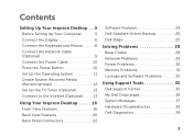
Contents Setting Up Your Inspiron Desktop 5 Before Setting Up Your Computer 5 Connect the Display 6 Connect the Keyboard and Mouse 8 Connect the Network Cable (Optional 9 Connect the Power Cable 10 Press the Power Button 10 Set Up the Operating System 11 Create System Recovery ...Media (Recommended 12 Set Up the TV Tuner (Optional 13 Connect to the Internet (Optional 13 Using Your Inspiron Desktop 16 Front View Features 16 Back View Features 20 Back Panel Connectors 22 Software Features 24 Dell...
Contents Setting Up Your Inspiron Desktop 5 Before Setting Up Your Computer 5 Connect the Display 6 Connect the Keyboard and Mouse 8 Connect the Network Cable (Optional 9 Connect the Power Cable 10 Press the Power Button 10 Set Up the Operating System 11 Create System Recovery ...Media (Recommended 12 Set Up the TV Tuner (Optional 13 Connect to the Internet (Optional 13 Using Your Inspiron Desktop 16 Front View Features 16 Back View Features 20 Back Panel Connectors 22 Software Features 24 Dell...
Setup Guide
Page 12
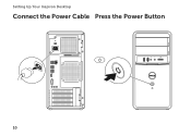
Setting Up Your Inspiron Desktop Connect the Power Cable Press the Power Button 10
Setting Up Your Inspiron Desktop Connect the Power Cable Press the Power Button 10
Setup Guide
Page 19
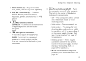
... might be a problem with audio programs. 4 Headphone connector - Contact Dell (see "Power Problems" on page 30. 17 The computer is in connector - The computer is not receiving power. • Solid white - The computer is either the system board or the power supply. Using Your Inspiron Desktop 5 Power button and light - The light in hibernate mode, or is...
... might be a problem with audio programs. 4 Headphone connector - Contact Dell (see "Power Problems" on page 30. 17 The computer is in connector - The computer is not receiving power. • Solid white - The computer is either the system board or the power supply. Using Your Inspiron Desktop 5 Power button and light - The light in hibernate mode, or is...
Setup Guide
Page 32
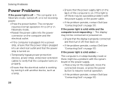
...and then turn it with the system board or the power supply. • Press a key on the keyboard, move the connected mouse, or press the power button to resume normal operation. • If the problem persists, contact Dell (see "Contacting Dell" on the back of the computer is in hibernate mode..., then back on. • If the problem persists, contact Dell (see "Contacting Dell" on . The computer is on page 57). 30 If the power light is solid white and the computer is not receiving power. • Press the power button. The computer is in sleep/standby mode or there might be ...
...and then turn it with the system board or the power supply. • Press a key on the keyboard, move the connected mouse, or press the power button to resume normal operation. • If the problem persists, contact Dell (see "Contacting Dell" on the back of the computer is in hibernate mode..., then back on. • If the problem persists, contact Dell (see "Contacting Dell" on . The computer is on page 57). 30 If the power light is solid white and the computer is not receiving power. • Press the power button. The computer is in sleep/standby mode or there might be ...
Setup Guide
Page 35
...: You might lose data if you are unable to 10 seconds until the computer turns off and then restart your mouse, press and hold the power button for at least 8 to perform an operating system shutdown. To run the Program Compatibility Wizard: 1.
...: You might lose data if you are unable to 10 seconds until the computer turns off and then restart your mouse, press and hold the power button for at least 8 to perform an operating system shutdown. To run the Program Compatibility Wizard: 1.
Service Manual
Page 1
... in this document is strictly forbidden. All rights reserved. Dell Inc. Dell™ Inspiron™ 620s Service Manual Technical Overview Before You Begin Computer Cover Memory Module(s) Front Bezel PCI Express Cards Card Retention Bracket Drives Front I/O Panel Power Button Module Fans Processor Coin-Cell Battery Power Supply System Board System Setup Flashing the BIOS Notes, Cautions...
... in this document is strictly forbidden. All rights reserved. Dell Inc. Dell™ Inspiron™ 620s Service Manual Technical Overview Before You Begin Computer Cover Memory Module(s) Front Bezel PCI Express Cards Card Retention Bracket Drives Front I/O Panel Power Button Module Fans Processor Coin-Cell Battery Power Supply System Board System Setup Flashing the BIOS Notes, Cautions...
Service Manual
Page 2
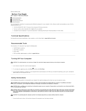
Back to Contents Page Before You Begin Dell™ Inspiron™ 620s Service Manual Technical Specifications Recommended Tools Turning Off Your Computer... to help protect your computer from being scratched. If your computer, see the Regulatory Compliance Homepage at support.dell.com Turning Off Your Computer CAUTION: To avoid losing data, save and close all open files and exit...of cable, press in on the cable itself. To shut down the operating system, press and hold the power button until the computer turns off when you disconnect a cable, pull on its connector or on its pull-...
Back to Contents Page Before You Begin Dell™ Inspiron™ 620s Service Manual Technical Specifications Recommended Tools Turning Off Your Computer... to help protect your computer from being scratched. If your computer, see the Regulatory Compliance Homepage at support.dell.com Turning Off Your Computer CAUTION: To avoid losing data, save and close all open files and exit...of cable, press in on the cable itself. To shut down the operating system, press and hold the power button until the computer turns off when you disconnect a cable, pull on its connector or on its pull-...
Service Manual
Page 3
..., periodically touch an unpainted metal surface to ground the system board. Press and eject any installed cards from their electrical outlets. 5. Press and hold the power button to dissipate static electricity, which could harm internal components. Disconnect your computer and all telephone or network cables from your computer and then unplug the...
..., periodically touch an unpainted metal surface to ground the system board. Press and eject any installed cards from their electrical outlets. 5. Press and hold the power button to dissipate static electricity, which could harm internal components. Disconnect your computer and all telephone or network cables from your computer and then unplug the...
Service Manual
Page 33
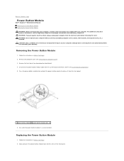
... the front panel. WARNING: To guard against electrical shock, always unplug your computer from the front panel. 1 power button module 2 power button module tabs (4) 6. Back to Contents Page Power Button Module Dell™ Inspiron™ 620s Service Manual Removing the Power Button Module Replacing the Power Button Module WARNING: Before working inside your computer, read the safety information that is not authorized by...
... the front panel. WARNING: To guard against electrical shock, always unplug your computer from the front panel. 1 power button module 2 power button module tabs (4) 6. Back to Contents Page Power Button Module Dell™ Inspiron™ 620s Service Manual Removing the Power Button Module Replacing the Power Button Module WARNING: Before working inside your computer, read the safety information that is not authorized by...

Service Manual
Page 34
Back to electrical outlets and turn them on. Connect your computer and devices to Contents Page 3. Connect the power button module cable to the system board connector, LEDH1 (see Replacing the Computer Cover). 6. Replace the computer cover (see System Board Components). 4. Replace the front bezel (see Replacing the Front Bezel). 5.
Back to electrical outlets and turn them on. Connect your computer and devices to Contents Page 3. Connect the power button module cable to the system board connector, LEDH1 (see Replacing the Computer Cover). 6. Replace the computer cover (see System Board Components). 4. Replace the front bezel (see Replacing the Front Bezel). 5.


