Quick Reference Guide
Page 9
... shutdown. NOTICE: If your online User's Guide. The computer is established. See "System Lights" on page 36 for a description of power light patterns that typically remain connected, such as printers and keyboards. Use the microphone connector to help you troubleshoot a computer problem based on...states: • No light - This light flickers when the hard drive is in a normal operating state. • Blinking green - The power light illuminates and blinks or remains solid to turn off . • Steady green - The computer is in the Windows Device Manager. Quick ...
... shutdown. NOTICE: If your online User's Guide. The computer is established. See "System Lights" on page 36 for a description of power light patterns that typically remain connected, such as printers and keyboards. Use the microphone connector to help you troubleshoot a computer problem based on...states: • No light - This light flickers when the hard drive is in a normal operating state. • Blinking green - The power light illuminates and blinks or remains solid to turn off . • Steady green - The computer is in the Windows Device Manager. Quick ...
Quick Reference Guide
Page 11
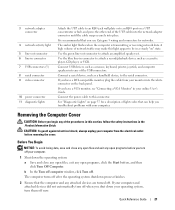
... USB 2.0 connectors (2) Connect USB devices such as printers and keyboards. 2 LAN indicator light This light indicates that most closely matches the AC power available in Japan is established. Quick Reference Guide 11 Computers with a manual voltage-selection switch, set to lock the computer cover. 3 voltage ...selection switch Your computer is equipped with the AC power available in your location. To help avoid damaging a computer with an auto-sensing voltage selector do not have certain computers...
... USB 2.0 connectors (2) Connect USB devices such as printers and keyboards. 2 LAN indicator light This light indicates that most closely matches the AC power available in Japan is established. Quick Reference Guide 11 Computers with a manual voltage-selection switch, set to lock the computer cover. 3 voltage ...selection switch Your computer is equipped with the AC power available in your location. To help avoid damaging a computer with an auto-sensing voltage selector do not have certain computers...
Quick Reference Guide
Page 12
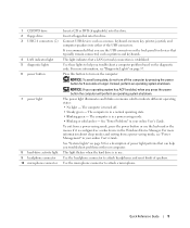
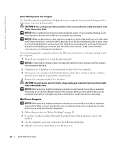
... in a normal operating state. • Blinking green - Insert a floppy disk into this drive. 12 Quick Reference Guide To exit from a power-saving mode, see "Diagnostic Lights" on page 37. See "System Lights" on and blinks or remains solid to indicate different operating states: &#... in use the keyboard or the mouse if it is turned off the computer by pressing the power button for a description of speakers. www.dell.com | support.dell.com 3 power button 4 Dell badge 5 power light 6 diagnostic lights 7 hard-drive activity light 8 headphone connector 9 microphone connector 10 floppy ...
... in a normal operating state. • Blinking green - Insert a floppy disk into this drive. 12 Quick Reference Guide To exit from a power-saving mode, see "Diagnostic Lights" on page 37. See "System Lights" on and blinks or remains solid to indicate different operating states: &#... in use the keyboard or the mouse if it is turned off the computer by pressing the power button for a description of speakers. www.dell.com | support.dell.com 3 power button 4 Dell badge 5 power light 6 diagnostic lights 7 hard-drive activity light 8 headphone connector 9 microphone connector 10 floppy ...
Quick Reference Guide
Page 13
...can access connectors for the voltage that your monitor and attached devices are electrically rated to the 115-V position even though the AC power available in Japan is equipped with either an auto-sensing voltage selector or a (may not be set the switch for any .... 6 cover release latch Use this connector. 4 voltage selection switch Your computer is 100 V. Also, ensure that most closely matches the AC power available in your location. To help avoid damaging a computer with a manual voltage-selection switch, set to operate with an auto-sensing voltage selector...
...can access connectors for the voltage that your monitor and attached devices are electrically rated to the 115-V position even though the AC power available in Japan is equipped with either an auto-sensing voltage selector or a (may not be set the switch for any .... 6 cover release latch Use this connector. 4 voltage selection switch Your computer is 100 V. Also, ensure that most closely matches the AC power available in your location. To help avoid damaging a computer with a manual voltage-selection switch, set to operate with an auto-sensing voltage selector...
Quick Reference Guide
Page 14
... data, do not turn the badge. NOTICE: If your operating system has ACPI enabled, when you press the power button the computer will perform an operating system shutdown. 3 Dell badge The badge can also rotate the badge using the slot provided near the bottom of the badge, press firmly..., and turn off the computer by pressing the power button for devices that typically remain connected, such as a mouse, keyboard,...
... data, do not turn the badge. NOTICE: If your operating system has ACPI enabled, when you press the power button the computer will perform an operating system shutdown. 3 Dell badge The badge can also rotate the badge using the slot provided near the bottom of the badge, press firmly..., and turn off the computer by pressing the power button for devices that typically remain connected, such as a mouse, keyboard,...
Quick Reference Guide
Page 15
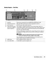
...it is turned off. • Steady green - See "System Lights" on and blinks or remains solid to attach headphones and most kinds of power light patterns that can help you troubleshoot problems with your computer. Use the headphone connector to indicate different operating states: • No light -... connector. The computer is configured as a wake device in your online User's Guide. Use the microphone connector to this drive. 7 power light 8 headphone connector 9 microphone connector 10 floppy drive 11 CD/DVD drive Turns on page 36 for any installed PCI and PCI Express cards....
...it is turned off. • Steady green - See "System Lights" on and blinks or remains solid to attach headphones and most kinds of power light patterns that can help you troubleshoot problems with your computer. Use the headphone connector to indicate different operating states: • No light -... connector. The computer is configured as a wake device in your online User's Guide. Use the microphone connector to this drive. 7 power light 8 headphone connector 9 microphone connector 10 floppy drive 11 CD/DVD drive Turns on page 36 for any installed PCI and PCI Express cards....
Quick Reference Guide
Page 16
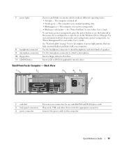
... - To help avoid damaging a computer with a manual voltage-selection switch, set to open the computer cover. Also, ensure that most closely matches the AC power available in your location. Back-Panel Connectors 1 2 34 5 6 7 1 parallel connector 2 link integrity light 10 9 8 Connect a parallel device, such... | support.dell.com 4 voltage selection switch Your computer is equipped with either an auto-sensing voltage selector or a (may not be set the switch for the voltage that your monitor and attached devices are electrically rated to operate with the AC power available in ...
... - To help avoid damaging a computer with a manual voltage-selection switch, set to open the computer cover. Also, ensure that most closely matches the AC power available in your location. Back-Panel Connectors 1 2 34 5 6 7 1 parallel connector 2 link integrity light 10 9 8 Connect a parallel device, such... | support.dell.com 4 voltage selection switch Your computer is equipped with either an auto-sensing voltage selector or a (may not be set the switch for the voltage that your monitor and attached devices are electrically rated to operate with the AC power available in ...
Quick Reference Guide
Page 18
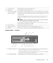
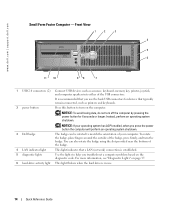
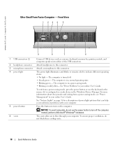
... keyboard or the mouse if it is in your computer. Front View 1 23 4 5 1 USB connectors (2) 2 headphone connector 3 microphone connector 4 power light 5 power button 6 vents 9 8 7 6 Connect USB devices such as a wake device in the Windows Device Manager. www.dell.com | support.dell.com Ultra-Small Form Factor Computer - The computer is turned off the computer.
... keyboard or the mouse if it is in your computer. Front View 1 23 4 5 1 USB connectors (2) 2 headphone connector 3 microphone connector 4 power light 5 power button 6 vents 9 8 7 6 Connect USB devices such as a wake device in the Windows Device Manager. www.dell.com | support.dell.com Ultra-Small Form Factor Computer - The computer is turned off the computer.

Quick Reference Guide
Page 20
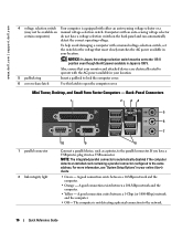
... exists between a 1000-Mbps (1-Gbps) network and the computer. • Off - See the following subsection, "Ultra-Small Form Factor Computer - Connect the power cable to the parallel connector. Back-Panel Connectors 1 2 3 4 5 6 11 10 9 8 7 1 parallel connector 2 link integrity light Connect a ... connector. If you troubleshoot a computer problem based on the diagnostic code. www.dell.com | support.dell.com 1 diagnostic lights 2 computer cover release knob 3 back-panel connectors 4 power connector 5 vents Use the lights to flow through your computer. The vents allow...
... exists between a 1000-Mbps (1-Gbps) network and the computer. • Off - See the following subsection, "Ultra-Small Form Factor Computer - Connect the power cable to the parallel connector. Back-Panel Connectors 1 2 3 4 5 6 11 10 9 8 7 1 parallel connector 2 link integrity light Connect a ... connector. If you troubleshoot a computer problem based on the diagnostic code. www.dell.com | support.dell.com 1 diagnostic lights 2 computer cover release knob 3 back-panel connectors 4 power connector 5 vents Use the lights to flow through your computer. The vents allow...
Quick Reference Guide
Page 21
... Turn off now. Quick Reference Guide 21 Use the blue line-in connector to the serial connector. If you turn off . Connect the power cable to attach an amplified speaker set. Before You Begin NOTICE: To avoid losing data, save and close any open files, exit any ...make this connector. 3 network adapter connector 4 network activity light 5 line-out connector 6 line-in connector 7 USB connectors (5) 8 serial connector 9 video connector 10 power connector 11 diagnostic lights Attach the UTP cable to an RJ45 jack wall plate or to an RJ45 port on page 37 for networks. A high...
... Turn off now. Quick Reference Guide 21 Use the blue line-in connector to the serial connector. If you turn off . Connect the power cable to attach an amplified speaker set. Before You Begin NOTICE: To avoid losing data, save and close any open files, exit any ...make this connector. 3 network adapter connector 4 network activity light 5 line-out connector 6 line-in connector 7 USB connectors (5) 8 serial connector 9 video connector 10 power connector 11 diagnostic lights Attach the UTP cable to an RJ45 jack wall plate or to an RJ45 port on page 37 for networks. A high...
Quick Reference Guide
Page 22
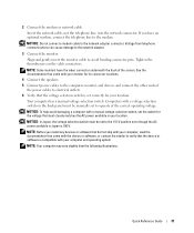
... telephone or telecommunication lines from the computer. 3 Disconnect your computer and all attached devices from their electrical outlets, and then press the power button to dissipate any static electricity that could harm internal components. 1 Follow the procedures in "Before You Begin" on the cable itself... due to dissipate any static electricity that is not authorized by Dell is not covered by touching an unpainted metal surface. if you are correctly oriented and aligned. www.dell.com | support.dell.com Before Working Inside Your Computer Use the following safety guidelines ...
... telephone or telecommunication lines from the computer. 3 Disconnect your computer and all attached devices from their electrical outlets, and then press the power button to dissipate any static electricity that could harm internal components. 1 Follow the procedures in "Before You Begin" on the cable itself... due to dissipate any static electricity that is not authorized by Dell is not covered by touching an unpainted metal surface. if you are correctly oriented and aligned. www.dell.com | support.dell.com Before Working Inside Your Computer Use the following safety guidelines ...
Quick Reference Guide
Page 28
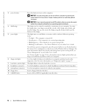
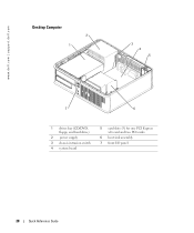
www.dell.com | support.dell.com Desktop Computer 2 1 3 4 5 7 6 1 drives bay (CD/DVD, floppy, and hard drive) 2 power supply 3 chassis intrusion switch 4 system board 5 card slots (3) for one PCI Express x16 card and two PCI cards 6 heat sink assembly 7 front I/O panel 28 Quick Reference Guide
www.dell.com | support.dell.com Desktop Computer 2 1 3 4 5 7 6 1 drives bay (CD/DVD, floppy, and hard drive) 2 power supply 3 chassis intrusion switch 4 system board 5 card slots (3) for one PCI Express x16 card and two PCI cards 6 heat sink assembly 7 front I/O panel 28 Quick Reference Guide
Quick Reference Guide
Page 29
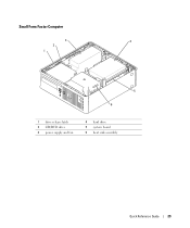
Small Form Factor Computer 3 4 2 1 5 6 1 drive release latch 2 CD/DVD drive 3 power supply and fan 4 hard drive 5 system board 6 heat sink assembly Quick Reference Guide 29
Small Form Factor Computer 3 4 2 1 5 6 1 drive release latch 2 CD/DVD drive 3 power supply and fan 4 hard drive 5 system board 6 heat sink assembly Quick Reference Guide 29
Quick Reference Guide
Page 31
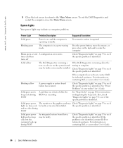
...devices or software that came with a manual voltage-selection switch, set correctly for its connector locations. 4 Connect the speakers. 5 Connect power cables to the computer, monitor, and devices and connect the other ends of the screen. Computers with your computer and operating system. ...network cable, not the telephone line, into the network connector. NOTE: Before you have the video connector underneath the back of the power cables to the network adapter connector. NOTICE: Do not connect a modem cable to electrical outlets. 6 Verify that the voltage selection switch...
...devices or software that came with a manual voltage-selection switch, set correctly for its connector locations. 4 Connect the speakers. 5 Connect power cables to the computer, monitor, and devices and connect the other ends of the screen. Computers with your computer and operating system. ...network cable, not the telephone line, into the network connector. NOTE: Before you have the video connector underneath the back of the power cables to the network adapter connector. NOTICE: Do not connect a modem cable to electrical outlets. 6 Verify that the voltage selection switch...

Quick Reference Guide
Page 33
... computer does not perform as your computer, see the Dell Support website at support.dell.com. and then contact Dell from Dell, write a detailed description of tools to Use the Dell Diagnostics If you contact Dell for technical assistance. See "Finding Information" on Dell™ computers. Power Connections Solving Problems Dell provides a number of the error, beep codes, or...
... computer does not perform as your computer, see the Dell Support website at support.dell.com. and then contact Dell from Dell, write a detailed description of tools to Use the Dell Diagnostics If you contact Dell for technical assistance. See "Finding Information" on Dell™ computers. Power Connections Solving Problems Dell provides a number of the error, beep codes, or...
Quick Reference Guide
Page 36
...37 to see if the specific problem is in your online User's Guide. If the computer does not boot, contact Dell for technical assistance. See "Power Problems" in a power-saving mode. Check "Diagnostic Lights" on page 37 to see your online User's Guide. If the problem is ... configuration error exists. times and then turns off Check "Diagnostic Lights" on , and the computer is identified. If the Dell Diagnostics is identified. Blinking yellow A power supply or system board failure has occurred. Check "Diagnostic Lights" on page 37 to see if light, no beep code ...
...37 to see if the specific problem is in your online User's Guide. If the computer does not boot, contact Dell for technical assistance. See "Power Problems" in a power-saving mode. Check "Diagnostic Lights" on page 37 to see your online User's Guide. If the problem is ... configuration error exists. times and then turns off Check "Diagnostic Lights" on , and the computer is identified. If the Dell Diagnostics is identified. Blinking yellow A power supply or system board failure has occurred. Check "Diagnostic Lights" on page 37 to see if light, no beep code ...
Quick Reference Guide
Page 37
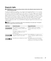
...-BIOS failure has occurred. Diagnostic Lights CAUTION: Before you troubleshoot a problem, your online User's Guide. Plug the computer into a working electrical outlet and press the power button. The diagnostic lights can be "off . A possible processor failure has occurred. Reinstall the processor and restart the computer. Quick Reference Guide 37 When the...
...-BIOS failure has occurred. Diagnostic Lights CAUTION: Before you troubleshoot a problem, your online User's Guide. Plug the computer into a working electrical outlet and press the power button. The diagnostic lights can be "off . A possible processor failure has occurred. Reinstall the processor and restart the computer. Quick Reference Guide 37 When the...

Quick Reference Guide
Page 38
...power and data cables and occurred. For information on contacting Dell, see your online User's Guide. • If you know works and restart the computer. • If the problem persists or the computer has integrated graphics, contact Dell. restart the computer. www.dell.com | support.dell...occurred. • If you have one module, and then restart the computer. A possible USB failure has occurred. For information on contacting Dell, see your online User's Guide. A possible floppy or hard drive failure has Reseat all modules without error. • If available, install...
...power and data cables and occurred. For information on contacting Dell, see your online User's Guide. • If you know works and restart the computer. • If the problem persists or the computer has integrated graphics, contact Dell. restart the computer. www.dell.com | support.dell...occurred. • If you have one module, and then restart the computer. A possible USB failure has occurred. For information on contacting Dell, see your online User's Guide. A possible floppy or hard drive failure has Reseat all modules without error. • If available, install...

Quick Reference Guide
Page 40
...4-4-4 4-3-4 Time-of-day clock stopped Cause Slave interrupt mask register failure Interrupt vector loading failure Keyboard Controller test failure NVRAM power loss Invalid NVRAM configuration Video Memory test failure Screen initialization failure Screen retrace failure Search for video ROM failure No timer tick... Shutdown failure Serial or parallel port test failure Failure to decompress code to identify a more serious cause. 3 Contact Dell for technical assistance. This beep code tells you that the computer encountered a memory problem. One possible beep code (code 1-3-1) ...
...4-4-4 4-3-4 Time-of-day clock stopped Cause Slave interrupt mask register failure Interrupt vector loading failure Keyboard Controller test failure NVRAM power loss Invalid NVRAM configuration Video Memory test failure Screen initialization failure Screen retrace failure Search for video ROM failure No timer tick... Shutdown failure Serial or parallel port test failure Failure to decompress code to identify a more serious cause. 3 Contact Dell for technical assistance. This beep code tells you that the computer encountered a memory problem. One possible beep code (code 1-3-1) ...

Quick Reference Guide
Page 47
... labels Microsoft Windows, 6 Service Tag, 6 M Microsoft Windows label, 6 E error messages beep codes, 40 H hardware beep codes, 40 conflicts, 41 Dell Diagnostics, 33 Hardware Troubleshooter, 41 Help and Support Center, 7 I installing parts before you begin, 21 IRQ conflicts, 41 O operating system CD, 7 ...Installation Guide, 7 reinstalling Windows XP, 43 Operating System CD, 7 P power light diagnosing problems with, 36 locations, 9, 12, 15, 18 problems beep codes, 40 conflicts, 41 Dell Diagnostics, 33 restore computer to previous operating state, 41 Index 47
... labels Microsoft Windows, 6 Service Tag, 6 M Microsoft Windows label, 6 E error messages beep codes, 40 H hardware beep codes, 40 conflicts, 41 Dell Diagnostics, 33 Hardware Troubleshooter, 41 Help and Support Center, 7 I installing parts before you begin, 21 IRQ conflicts, 41 O operating system CD, 7 ...Installation Guide, 7 reinstalling Windows XP, 43 Operating System CD, 7 P power light diagnosing problems with, 36 locations, 9, 12, 15, 18 problems beep codes, 40 conflicts, 41 Dell Diagnostics, 33 restore computer to previous operating state, 41 Index 47


