Quick Reference Guide
Page 3
...Desktop, and Small Form Factor Computers - Back-Panel Connectors 16 Ultra-Small Form Factor Computer - Back View 19 Removing the Computer Cover 21 Before You Begin 21 Mini Tower Computer 22 Desktop Computer 24 Small Form Factor Computer 25 Ultra-Small Form Factor Computer 26 Inside... Computer 29 Ultra-Small Form Factor Computer 30 Setting Up Your Computer 30 Solving Problems 33 Dell Diagnostics 33 System Lights 36 Diagnostic Lights 37 Beep Codes 40 Running the Dell™ IDE Hard Drive Diagnostics 41 Resolving Software and Hardware Incompatibilities 41 Contents 3 Back View...
...Desktop, and Small Form Factor Computers - Back-Panel Connectors 16 Ultra-Small Form Factor Computer - Back View 19 Removing the Computer Cover 21 Before You Begin 21 Mini Tower Computer 22 Desktop Computer 24 Small Form Factor Computer 25 Ultra-Small Form Factor Computer 26 Inside... Computer 29 Ultra-Small Form Factor Computer 30 Setting Up Your Computer 30 Solving Problems 33 Dell Diagnostics 33 System Lights 36 Diagnostic Lights 37 Beep Codes 40 Running the Dell™ IDE Hard Drive Diagnostics 41 Resolving Software and Hardware Incompatibilities 41 Contents 3 Back View...
Quick Reference Guide
Page 11
...sensing voltage selector do not have certain computers) a voltage selection switch on voltage-selection switch. It is recommended that you to open the computer cover. 2 padlock ring Insert a padlock to the 115-V position even though the AC power available in Japan is 100 V. Desktop Computer - Also...not be set the switch for the voltage that most closely matches the AC power available in your location. Quick Reference Guide 11 1 cover release latch This latch allows you use the back USB connectors for devices that typically remain connected, such as a mouse, keyboard, memory...
...sensing voltage selector do not have certain computers) a voltage selection switch on voltage-selection switch. It is recommended that you to open the computer cover. 2 padlock ring Insert a padlock to the 115-V position even though the AC power available in Japan is 100 V. Desktop Computer - Also...not be set the switch for the voltage that most closely matches the AC power available in your location. Quick Reference Guide 11 1 cover release latch This latch allows you use the back USB connectors for devices that typically remain connected, such as a mouse, keyboard, memory...
Quick Reference Guide
Page 13
.... Quick Reference Guide 13 Also, ensure that most closely matches the AC power available in your location. 5 padlock ring Insert a padlock to lock the computer cover. 6 cover release latch Use this connector. 4 voltage selection switch Your computer is equipped with the AC power available in Japan is 100 V. To help avoid damaging...
.... Quick Reference Guide 13 Also, ensure that most closely matches the AC power available in your location. 5 padlock ring Insert a padlock to lock the computer cover. 6 cover release latch Use this connector. 4 voltage selection switch Your computer is equipped with the AC power available in Japan is 100 V. To help avoid damaging...
Quick Reference Guide
Page 16
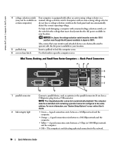
...help avoid damaging a computer with the AC power available in your location. 5 padlock ring Insert a padlock to lock the computer cover. 6 cover release latch Use this latch to open the computer cover. Back-Panel Connectors 1 2 34 5 6 7 1 parallel connector 2 link integrity light 10 9 8 Connect a parallel device...can automatically detect the correct operating voltage. For more information, see "System Setup Options" in your location. www.dell.com | support.dell.com 4 voltage selection switch Your computer is equipped with either an auto-sensing voltage selector or a (may ...
...help avoid damaging a computer with the AC power available in your location. 5 padlock ring Insert a padlock to lock the computer cover. 6 cover release latch Use this latch to open the computer cover. Back-Panel Connectors 1 2 34 5 6 7 1 parallel connector 2 link integrity light 10 9 8 Connect a parallel device...can automatically detect the correct operating voltage. For more information, see "System Setup Options" in your location. www.dell.com | support.dell.com 4 voltage selection switch Your computer is equipped with either an auto-sensing voltage selector or a (may ...
Quick Reference Guide
Page 17
... network. NOTE: If you must use the connector on the card. A click indicates that you purchased an optional graphics card, this light appear to be covered by a cap. A high volume of the USB connectors. Connect USB devices such as a handheld device, to attach headphones and most speakers with your VGA-compatible...
... network. NOTE: If you must use the connector on the card. A click indicates that you purchased an optional graphics card, this light appear to be covered by a cap. A high volume of the USB connectors. Connect USB devices such as a handheld device, to attach headphones and most speakers with your VGA-compatible...

Quick Reference Guide
Page 20
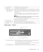
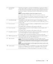
... computer. A good connection exists between a 1000-Mbps (1-Gbps) network and the computer. • Off - www.dell.com | support.dell.com 1 diagnostic lights 2 computer cover release knob 3 back-panel connectors 4 power connector 5 vents Use the lights to help you have a USB printer,...Ultra-Small Form Factor Computer - A good connection exists between a 10-Mbps network and the computer. • Orange - Connect the power cable to remove the cover. Back-Panel Connectors 1 2 3 4 5 6 11 10 9 8 7 1 parallel connector 2 link integrity light Connect a parallel device, such as a...
... computer. A good connection exists between a 1000-Mbps (1-Gbps) network and the computer. • Off - www.dell.com | support.dell.com 1 diagnostic lights 2 computer cover release knob 3 back-panel connectors 4 power connector 5 vents Use the lights to help you have a USB printer,...Ultra-Small Form Factor Computer - A good connection exists between a 10-Mbps network and the computer. • Orange - Connect the power cable to remove the cover. Back-Panel Connectors 1 2 3 4 5 6 11 10 9 8 7 1 parallel connector 2 link integrity light Connect a parallel device, such as a...
Quick Reference Guide
Page 21
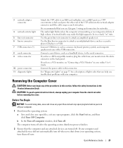
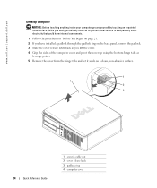
...you use Category 5 wiring and connectors for a description of light codes that you troubleshoot problems with your online User's Guide. Removing the Computer Cover CAUTION: Before you turn off your computer. 1 Shut down your operating system, turn off when you have a VGA monitor, see "Connecting...set. Before You Begin NOTICE: To avoid losing data, save and close any open files, exit any open programs before removing the cover. CAUTION: To guard against electrical shock, always unplug your computer from your computer and attached devices did not automatically turn them off ...
...you use Category 5 wiring and connectors for a description of light codes that you troubleshoot problems with your online User's Guide. Removing the Computer Cover CAUTION: Before you turn off your computer. 1 Shut down your operating system, turn off when you have a VGA monitor, see "Connecting...set. Before You Begin NOTICE: To avoid losing data, save and close any open files, exit any open programs before removing the cover. CAUTION: To guard against electrical shock, always unplug your computer from your computer and attached devices did not automatically turn them off ...
Quick Reference Guide
Page 22
...against electrical shock, always unplug your computer from the network wall jack. 2 Disconnect any static electricity that is not authorized by Dell is not covered by your computer, ground yourself by touching an unpainted metal surface, such as you disconnect the cable. While you work , periodically...the computer. 1 Turn off your computer if it is attached. To avoid damaging the computer, perform the following steps before removing the cover. Also, before you are correctly oriented and aligned. Some cables have installed a padlock through the padlock ring on the back panel, ...
...against electrical shock, always unplug your computer from the network wall jack. 2 Disconnect any static electricity that is not authorized by Dell is not covered by your computer, ground yourself by touching an unpainted metal surface, such as you disconnect the cable. While you work , periodically...the computer. 1 Turn off your computer if it is attached. To avoid damaging the computer, perform the following steps before removing the cover. Also, before you are correctly oriented and aligned. Some cables have installed a padlock through the padlock ring on the back panel, ...

Quick Reference Guide
Page 23
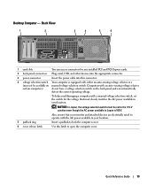
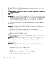
5 Grip the sides of the computer cover and pivot the cover up using the bottom hinge tabs as leverage points. 6 Remove the cover from the hinge tabs and set it aside on a soft non-abrasive surface. 1 2 1 3 4 2 3 1 security cable slot 2 cover release latch 3 padlock ring 4 computer cover Quick Reference Guide 23
5 Grip the sides of the computer cover and pivot the cover up using the bottom hinge tabs as leverage points. 6 Remove the cover from the hinge tabs and set it aside on a soft non-abrasive surface. 1 2 1 3 4 2 3 1 security cable slot 2 cover release latch 3 padlock ring 4 computer cover Quick Reference Guide 23
Quick Reference Guide
Page 24
www.dell.com | support.dell.com Desktop Computer NOTICE: Before touching anything inside your computer, ground yourself by touching an unpainted metal surface. While you work, periodically touch an unpainted ... padlock ring on the back panel, remove the padlock. 3 Slide the cover release latch back as you lift the cover. 4 Grip the sides of the computer cover and pivot the cover up using the bottom hinge tabs as leverage points. 5 Remove the cover from the hinge tabs and set it aside on a clean, non-abrasive...
www.dell.com | support.dell.com Desktop Computer NOTICE: Before touching anything inside your computer, ground yourself by touching an unpainted metal surface. While you work, periodically touch an unpainted ... padlock ring on the back panel, remove the padlock. 3 Slide the cover release latch back as you lift the cover. 4 Grip the sides of the computer cover and pivot the cover up using the bottom hinge tabs as leverage points. 5 Remove the cover from the hinge tabs and set it aside on a clean, non-abrasive...

Quick Reference Guide
Page 25
... on the back panel, remove the padlock. 3 Slide the cover release latch back as you lift the cover. 4 Grip the sides of the computer cover and pivot the cover up using the bottom hinge tabs as leverage points. 5 Remove the cover from the hinge tabs and set it aside on a clean,... non-abrasive surface. 1 4 2 3 1 security cable slot 2 cover release latch 3 padlock ring 4 computer cover Quick Reference ...
... on the back panel, remove the padlock. 3 Slide the cover release latch back as you lift the cover. 4 Grip the sides of the computer cover and pivot the cover up using the bottom hinge tabs as leverage points. 5 Remove the cover from the hinge tabs and set it aside on a clean,... non-abrasive surface. 1 4 2 3 1 security cable slot 2 cover release latch 3 padlock ring 4 computer cover Quick Reference ...

Quick Reference Guide
Page 26
While you work, periodically touch an unpainted metal surface to dissipate any static electricity that could harm internal components. 1 Follow the procedures in "Before You Begin" on page 21. 2 Rotate the cover release knob in a clockwise direction. 3 Slide the computer cover forward by touching an unpainted metal surface. www.dell.com | support.dell.com Ultra-Small Form Factor Computer NOTICE: Before touching anything inside your computer, ground yourself by approximately 1 cm (½ inch), or until it stops, and then raise the cover. 1 1 cover release knob 26 Quick Reference Guide
While you work, periodically touch an unpainted metal surface to dissipate any static electricity that could harm internal components. 1 Follow the procedures in "Before You Begin" on page 21. 2 Rotate the cover release knob in a clockwise direction. 3 Slide the computer cover forward by touching an unpainted metal surface. www.dell.com | support.dell.com Ultra-Small Form Factor Computer NOTICE: Before touching anything inside your computer, ground yourself by approximately 1 cm (½ inch), or until it stops, and then raise the cover. 1 1 cover release knob 26 Quick Reference Guide

Quick Reference Guide
Page 47
...codes, 40 restore to previous operating state, 41 conflicts software and hardware incompatibilities, 41 cover removing, 21 D Dell Premier Support website, 7 support site, 6 Dell Diagnostics, 33 diagnostics beep codes, 40 Dell Diagnostics, 33 Drivers and Utilities CD, 5 documentation device, 5 online, 6-7 Quick ...Windows, 6 Service Tag, 6 M Microsoft Windows label, 6 E error messages beep codes, 40 H hardware beep codes, 40 conflicts, 41 Dell Diagnostics, 33 Hardware Troubleshooter, 41 Help and Support Center, 7 I installing parts before you begin, 21 IRQ conflicts, 41 O operating system...
...codes, 40 restore to previous operating state, 41 conflicts software and hardware incompatibilities, 41 cover removing, 21 D Dell Premier Support website, 7 support site, 6 Dell Diagnostics, 33 diagnostics beep codes, 40 Dell Diagnostics, 33 Drivers and Utilities CD, 5 documentation device, 5 online, 6-7 Quick ...Windows, 6 Service Tag, 6 M Microsoft Windows label, 6 E error messages beep codes, 40 H hardware beep codes, 40 conflicts, 41 Dell Diagnostics, 33 Hardware Troubleshooter, 41 Help and Support Center, 7 I installing parts before you begin, 21 IRQ conflicts, 41 O operating system...
Setup Guide
Page 30
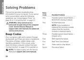
...replace parts, see the Service Manual at support.dell.com/manuals for advanced service instructions. If this occurs, write down the beep code and contact Dell (see "Contacting Dell" on page 57. Possible system board failure - INSPIRON Solving Problems This section provides troubleshooting information for ... guidelines, see "Using Support Tools" on page 35 or "Contacting Dell" on page 57) for assistance. Beep Code One Two Three Four Five Six Seven 28 Possible Problem Possible system board failure - WARNING: Only trained service personnel should remove the computer cover.
...replace parts, see the Service Manual at support.dell.com/manuals for advanced service instructions. If this occurs, write down the beep code and contact Dell (see "Contacting Dell" on page 57. Possible system board failure - INSPIRON Solving Problems This section provides troubleshooting information for ... guidelines, see "Using Support Tools" on page 35 or "Contacting Dell" on page 57) for assistance. Beep Code One Two Three Four Five Six Seven 28 Possible Problem Possible system board failure - WARNING: Only trained service personnel should remove the computer cover.
Service Manual
Page 1
Dell™ Inspiron™ 620s Service Manual Technical Overview Before You Begin Computer Cover Memory Module(s) Front Bezel PCI Express Cards Card Retention Bracket Drives Front I/O Panel Power Button Module Fans Processor Coin-Cell ... and trade names other countries. disclaims any manner whatsoever without notice. © 2011 Dell Inc. Dell Inc. A00 Regulatory model: D06D series Regulatory type: D06D001 Information in this text: Dell™, the DELL logo, and Inspiron-™ are either the entities claiming the marks and names or their products. Trademarks...
Dell™ Inspiron™ 620s Service Manual Technical Overview Before You Begin Computer Cover Memory Module(s) Front Bezel PCI Express Cards Card Retention Bracket Drives Front I/O Panel Power Button Module Fans Processor Coin-Cell ... and trade names other countries. disclaims any manner whatsoever without notice. © 2011 Dell Inc. Dell Inc. A00 Regulatory model: D06D series Regulatory type: D06D001 Information in this text: Dell™, the DELL logo, and Inspiron-™ are either the entities claiming the marks and names or their products. Trademarks...
Service Manual
Page 2
...computer from being scratched. As you pull connectors apart, keep them evenly aligned to Contents Page Before You Begin Dell™ Inspiron™ 620s Service Manual Technical Specifications Recommended Tools Turning Off Your Computer Safety Instructions This manual provides instructions for removing and installing ...1. if you disconnect the cable. Ensure that the work surface is flat and clean to servicing that the computer is not covered by performing the removal procedure in this type of your computer did not automatically turn off . Unless otherwise noted, each procedure ...
...computer from being scratched. As you pull connectors apart, keep them evenly aligned to Contents Page Before You Begin Dell™ Inspiron™ 620s Service Manual Technical Specifications Recommended Tools Turning Off Your Computer Safety Instructions This manual provides instructions for removing and installing ...1. if you disconnect the cable. Ensure that the work surface is flat and clean to servicing that the computer is not covered by performing the removal procedure in this type of your computer did not automatically turn off . Unless otherwise noted, each procedure ...
Service Manual
Page 4
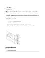
.... 1 front bezel 2 front bezel tabs (3) 3 front panel slots (4) 4 front bezel clamps (4) 5 front panel 6. Remove the computer cover (see the Regulatory Compliance Homepage at a time by your warranty. Back to Contents Page Front Bezel Dell™ Inspiron™ 620s Service Manual Removing the Front Bezel Replacing the Front Bezel WARNING: Before working inside your computer...
.... 1 front bezel 2 front bezel tabs (3) 3 front panel slots (4) 4 front bezel clamps (4) 5 front panel 6. Remove the computer cover (see the Regulatory Compliance Homepage at a time by your warranty. Back to Contents Page Front Bezel Dell™ Inspiron™ 620s Service Manual Removing the Front Bezel Replacing the Front Bezel WARNING: Before working inside your computer...
Service Manual
Page 5
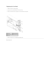
Back to Contents Page Rotate the front bezel towards the computer until the front bezel tabs snap into the front panel slots. 3. Replace the computer cover (see Replacing the Computer Cover). Replacing the Front Bezel 1. Follow the instructions in Before You Begin. 2. Align and insert the front bezel clamps into place. 1 front bezel 2 front bezel tabs (3) 3 front bezel clamps (4) 4 front panel slots (4) 5 front panel 4.
Back to Contents Page Rotate the front bezel towards the computer until the front bezel tabs snap into the front panel slots. 3. Replace the computer cover (see Replacing the Computer Cover). Replacing the Front Bezel 1. Follow the instructions in Before You Begin. 2. Align and insert the front bezel clamps into place. 1 front bezel 2 front bezel tabs (3) 3 front bezel clamps (4) 4 front panel slots (4) 5 front panel 4.
Service Manual
Page 7
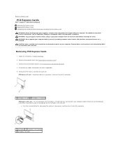
.... 1 securing tab 2 PCI Express x16 card slot 3 PCI Express x16 card Back to Contents Page PCI Express Cards Dell™ Inspiron™ 620s Service Manual Removing PCI Express Cards Replacing PCI Express Cards Configuring Your Computer After Removing or Installing the PCI Express Card WARNING...: Before working inside your computer, read the safety information that is not authorized by Dell is not covered by its top ...
.... 1 securing tab 2 PCI Express x16 card slot 3 PCI Express x16 card Back to Contents Page PCI Express Cards Dell™ Inspiron™ 620s Service Manual Removing PCI Express Cards Replacing PCI Express Cards Configuring Your Computer After Removing or Installing the PCI Express Card WARNING...: Before working inside your computer, read the safety information that is not authorized by Dell is not covered by its top ...
Service Manual
Page 10
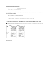
... Express Card. Connect the network cable to Disabled. 3. CAUTION: Do not route card cables over the cards can prevent the computer cover from closing properly or cause damage to the card. Go to Onboard Audio Controller and then change the setting to the integrated network connector... System Setup). 2. Reconnect the computer and devices to Disabled. 3. For information on . 8. Enter system setup (see Replacing the Computer Cover). 7. Back to Enabled. 3. Sound card Installed Removed 1. Enter system setup (see System Setup). 2. Go to Onboard Audio Controller and then...
... Express Card. Connect the network cable to Disabled. 3. CAUTION: Do not route card cables over the cards can prevent the computer cover from closing properly or cause damage to the card. Go to Onboard Audio Controller and then change the setting to the integrated network connector... System Setup). 2. Reconnect the computer and devices to Disabled. 3. For information on . 8. Enter system setup (see Replacing the Computer Cover). 7. Back to Enabled. 3. Sound card Installed Removed 1. Enter system setup (see System Setup). 2. Go to Onboard Audio Controller and then...


