
User Manual
Page 1
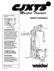
..., we are missing or damaged parts, we w!!! TO AVOID UNNECESSARY DELAYS, PLEASE CALL DIRECT TO OUR TOLL-FREE CUSTOMER HOT LINE. Read all precautions and instructions in this user's manual before using this owner's manual for future reference. Model No. CUSTOMER HOT LINE: 1-800...direct assistance from our factory. The trained technicians on our customer hot line will provide immediate assistance, free of charge to providing complete customer satisfaction. MST CAUTION! guerarztcc you . Save this equipment. WESY700920 Serial No. 0' 7/1, te,t 7frtabet USER'S MANUAL Serial Number...
..., we are missing or damaged parts, we w!!! TO AVOID UNNECESSARY DELAYS, PLEASE CALL DIRECT TO OUR TOLL-FREE CUSTOMER HOT LINE. Read all precautions and instructions in this user's manual before using this owner's manual for future reference. Model No. CUSTOMER HOT LINE: 1-800...direct assistance from our factory. The trained technicians on our customer hot line will provide immediate assistance, free of charge to providing complete customer satisfaction. MST CAUTION! guerarztcc you . Save this equipment. WESY700920 Serial No. 0' 7/1, te,t 7frtabet USER'S MANUAL Serial Number...
User Manual
Page 2
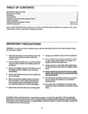
... an exercise that does not use of this or any exercise program, consult your physician. Cover the floor beneath the weight system for foot protection. 8. Make sure that the cables are on a level surface. TABLE OF CONTENTS IMPORTANT PRECAUTIONS BEFORE YOU BEGIN ASSEMBLY ADJUSTMENT TROUBLE-SHOOTING AND MAINTENANCE CABLE DIAGRAM ORDERING REPLACEMENT PARTS LIMITED WARRANTY 2 3 4 15 18 19 Back Cover Back Cover Note: A PART IDENTIFICATION CHART and a PARTS LIST/EXPLODED DRAWING are attached at...
... an exercise that does not use of this or any exercise program, consult your physician. Cover the floor beneath the weight system for foot protection. 8. Make sure that the cables are on a level surface. TABLE OF CONTENTS IMPORTANT PRECAUTIONS BEFORE YOU BEGIN ASSEMBLY ADJUSTMENT TROUBLE-SHOOTING AND MAINTENANCE CABLE DIAGRAM ORDERING REPLACEMENT PARTS LIMITED WARRANTY 2 3 4 15 18 19 Back Cover Back Cover Note: A PART IDENTIFICATION CHART and a PARTS LIST/EXPLODED DRAWING are attached at...
User Manual
Page 3
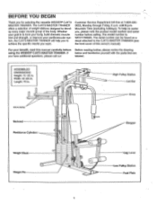
... TRAINER. until 6 p.m. To help you to tone your body, build dramatic muscle size and strength, or improve your benefit, read this owner's manual). If below and familiarize yourself with the parts that are you , please note the product model number and serial number before Before reading further, please review the drawing using the WEIDER° CJXT3 MASTER TRAINER. Width: 55 3/4 in. High Pulley Station Lat Bar Arms VISH Arms...
... TRAINER. until 6 p.m. To help you to tone your body, build dramatic muscle size and strength, or improve your benefit, read this owner's manual). If below and familiarize yourself with the parts that are you , please note the product model number and serial number before Before reading further, please review the drawing using the WEIDER° CJXT3 MASTER TRAINER. Width: 55 3/4 in. High Pulley Station Lat Bar Arms VISH Arms...
User Manual
Page 4
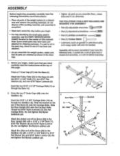
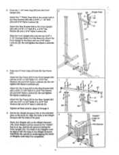
... will be needed. If a part is completed. • Read each assembly step before you begin , make sure that you assemble them, unless instructed to do otherwise. Press a 2" inner Cap (27) into the Base (4). Press the two 2" Outer Caps (88) onto the Stabilizer (5). Do not tighten the Nylon Locknut yet. Attach the Pulley Plate (20) to the Rear Upright (82) with two 5/16" x 2 3/4" Bolts (11...
... will be needed. If a part is completed. • Read each assembly step before you begin , make sure that you assemble them, unless instructed to do otherwise. Press a 2" inner Cap (27) into the Base (4). Press the two 2" Outer Caps (88) onto the Stabilizer (5). Do not tighten the Nylon Locknut yet. Attach the Pulley Plate (20) to the Rear Upright (82) with two 5/16" x 2 3/4" Bolts (11...
User Manual
Page 5
... (4). Attach the 1" Plastic Stop (64) to avoid Upping the stack of Weights until step 6 Is completed. Slide the Front Upright (42) onto the two 5/16" x 2 1/2" Carriage Bolts (1) in the Stop Bracket (63) with a 5/16" x 2 3/4" Bolt (11), 5/16" Rat Washer (8) and 5/16" Nylon Locknut (3). A 11 8 27 3 82 5 11 11 8 67 3 27 3 63 42 25 0 `Weider" Logo on top, and the pin...
... (4). Attach the 1" Plastic Stop (64) to avoid Upping the stack of Weights until step 6 Is completed. Slide the Front Upright (42) onto the two 5/16" x 2 1/2" Carriage Bolts (1) in the Stop Bracket (63) with a 5/16" x 2 3/4" Bolt (11), 5/16" Rat Washer (8) and 5/16" Nylon Locknut (3). A 11 8 27 3 82 5 11 11 8 67 3 27 3 63 42 25 0 `Weider" Logo on top, and the pin...
User Manual
Page 6
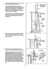
... Bushings (68). Set the Arm Frame Bushings and the Arm Frame on top. Insert the Weight Tube (80) into the Arm Frame (52). 8 Lubricate the upper axle on 25 Top Pin Groove 80 Welded Tube 79 25 73 72 3 67 8. Locate the lower ends of the Weight Tube. Attach the Arm Frame Bracket to the Top Frame with the 5/16" x Bolt 7 (7111 them...
... Bushings (68). Set the Arm Frame Bushings and the Arm Frame on top. Insert the Weight Tube (80) into the Arm Frame (52). 8 Lubricate the upper axle on 25 Top Pin Groove 80 Welded Tube 79 25 73 72 3 67 8. Locate the lower ends of the Weight Tube. Attach the Arm Frame Bracket to the Top Frame with the 5/16" x Bolt 7 (7111 them...

User Manual
Page 7
... Arm must bend toward the Round Cover Cap (see the inset drawing). Press a 1" Round Inner Cap (49) into one of the Arms (46). Attach the Handle with soapy water. Attach a 7" Handle (47) to the other Arm (46) to the lower axles on the Arm Frame (52). Attach the other Arm (46) in the Arm Frame (52) and the 10 Arms (46). 42 52-Lubricate...
... Arm must bend toward the Round Cover Cap (see the inset drawing). Press a 1" Round Inner Cap (49) into one of the Arms (46). Attach the Handle with soapy water. Attach a 7" Handle (47) to the other Arm (46) to the lower axles on the Arm Frame (52). Attach the other Arm (46) in the Arm Frame (52) and the 10 Arms (46). 42 52-Lubricate...
User Manual
Page 8
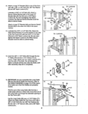
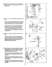
...Cable (66) that the Cables are properly routed. Lay the Long Cable (66) over a 4 1/2" Pulley (77). Lubricate a 5/16" x 2 1/4" Bolt (33). Insert two 3/8" x 1 3/4" Bolts (48) through the Indicated opening in the same manner. 13. Attach the Wide Swivel Bracket (71) to the other Arm...assemble the Long Cable (66) and the Short Cable (not shown), refer to swivel freely. 12 58 33-Lubricate , ( < 21 ; Attach the Pulley inside the Top Frame (67) with the Bolt and a 5/16" Nylon Locknut (3). 12. Do not thread the Nylon Locknuts all the way onto the Bolts until o 48 after assembly step...
...Cable (66) that the Cables are properly routed. Lay the Long Cable (66) over a 4 1/2" Pulley (77). Lubricate a 5/16" x 2 1/4" Bolt (33). Insert two 3/8" x 1 3/4" Bolts (48) through the Indicated opening in the same manner. 13. Attach the Wide Swivel Bracket (71) to the other Arm...assemble the Long Cable (66) and the Short Cable (not shown), refer to swivel freely. 12 58 33-Lubricate , ( < 21 ; Attach the Pulley inside the Top Frame (67) with the Bolt and a 5/16" Nylon Locknut (3). 12. Do not thread the Nylon Locknuts all the way onto the Bolts until o 48 after assembly step...

User Manual
Page 9
...Locknut onto the Bolt only two complete turns. Attach the Pulley and a Cable Trap (59) to the 19 Front Upright (42) with the 5/16" x 3 1/4" Bolt (35), a 5/16" Flat Washer (8) and 5/16" Nylon Locknut (3). Note: This Bracket is already attached to adjust the tension of the Long Cable (66) ...the Top Frame. Attach the Adjustment "U" Bracket (75) to the Narrow Swivel Bracket (58) on the left Arm (46) with a 3/8" x 1 3/4" Bolt (48) and 3/8" Nylon Locknut (21). 21 35 . - 0 16. Lay the Long Cable (66) over a 3 1/2" Pulley (15) (see the inset drawing). The Cable Trap must be ...
...Locknut onto the Bolt only two complete turns. Attach the Pulley and a Cable Trap (59) to the 19 Front Upright (42) with the 5/16" x 3 1/4" Bolt (35), a 5/16" Flat Washer (8) and 5/16" Nylon Locknut (3). Note: This Bracket is already attached to adjust the tension of the Long Cable (66) ...the Top Frame. Attach the Adjustment "U" Bracket (75) to the Narrow Swivel Bracket (58) on the left Arm (46) with a 3/8" x 1 3/4" Bolt (48) and 3/8" Nylon Locknut (21). 21 35 . - 0 16. Lay the Long Cable (66) over a 3 1/2" Pulley (15) (see the inset drawing). The Cable Trap must be ...
User Manual
Page 10
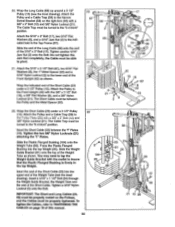
... the lower end of the Short Cable (23) into the top Weight (25). Tighten a 5/16" Nylon Locknut (3) onto the Bolt. The Cable Trap must be turned to the Front Upright (42) with the mallet to TIGHTENING THE CABLES on the Pulleys, and the Cables must be between the 1" Plates (78). Wrap the Long Cable (66) up around a 3 1/2" Pulley (15) (see the inset drawing). Attach the Pulley...
... the lower end of the Short Cable (23) into the top Weight (25). Tighten a 5/16" Nylon Locknut (3) onto the Bolt. The Cable Trap must be turned to the Front Upright (42) with the mallet to TIGHTENING THE CABLES on the Pulleys, and the Cables must be between the 1" Plates (78). Wrap the Long Cable (66) up around a 3 1/2" Pulley (15) (see the inset drawing). Attach the Pulley...
User Manual
Page 11
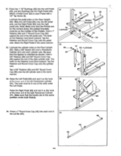
...). Tighten two 1/4" Nylon Locknuts (7) with a 5/16" x 2 3/4" Carriage Bolt (14) and the Seat Knob (40). Lubricate a 5/16" x 2 1/4" Bolt (33). Insert the two 1/4" x 2" Carriage Bolts (38) into the Leg Lever (29). Attach the Seat Frame with 1/4" Flat Washers (10) onto the Carriage Bolts. . , Wide End 37 , 38 ' . % 103 , 37 32 . ci 10 ' e,.< % 36 25. Set the bracket on the Seat Frame (36) onto the indicated pins...
...). Tighten two 1/4" Nylon Locknuts (7) with a 5/16" x 2 3/4" Carriage Bolt (14) and the Seat Knob (40). Lubricate a 5/16" x 2 1/4" Bolt (33). Insert the two 1/4" x 2" Carriage Bolts (38) into the Leg Lever (29). Attach the Seat Frame with 1/4" Flat Washers (10) onto the Carriage Bolts. . , Wide End 37 , 38 ' . % 103 , 37 32 . ci 10 ' e,.< % 36 25. Set the bracket on the Seat Frame (36) onto the indicated pins...
User Manual
Page 13
... a Resistance Cylinder (91) onto each Pedal with a 1/2" Tap Screw (6). Tap a 5/8" Retainer (95) and 5/8" Round Cover Cap (96) onto the left pedal axle, and the Right Pedal (89) onto the right pedal axle. Raise the Right Pedal (89) and rest it on the Retainer must bend outward. Lubricate the pedal axles on the correct sides; Attach the Right Pedal in one of the Lat Bar...
... a Resistance Cylinder (91) onto each Pedal with a 1/2" Tap Screw (6). Tap a 5/8" Retainer (95) and 5/8" Round Cover Cap (96) onto the left pedal axle, and the Right Pedal (89) onto the right pedal axle. Raise the Right Pedal (89) and rest it on the Retainer must bend outward. Lubricate the pedal axles on the correct sides; Attach the Right Pedal in one of the Lat Bar...
User Manual
Page 14
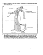
... manual. See the CABLE DIAGRAM on page 15 of all parts are not properly routed, they may be explained in the drawing below. 35 HIGH PULLEY BENCH PRESS/ BUTTERFLY COMBINATION •o VKR STEPPER 0 LEG EXTENSION 0' LOW PULLEY 36. Make sure that the cables move smoothly, locate and correct the problem before using the weight system, pull each cable a few times to the weight system in the locations shown in ADJUST...
... manual. See the CABLE DIAGRAM on page 15 of all parts are not properly routed, they may be explained in the drawing below. 35 HIGH PULLEY BENCH PRESS/ BUTTERFLY COMBINATION •o VKR STEPPER 0 LEG EXTENSION 0' LOW PULLEY 36. Make sure that the cables move smoothly, locate and correct the problem before using the weight system, pull each cable a few times to the weight system in the locations shown in ADJUST...
User Manual
Page 15
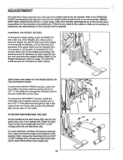
... exercise, switch the Arms (46) to be adjusted. The weight setting can be performed. ATTACHING AND REMOVING THE SEAT Set the bracket on the Seat Frame (36) onto the indicated pins on page 17 to find the actual amount of resistance at each station. 26 om 2 SWITCHING THE ARMS TO THE PRESS MODE OR THE BUTTERFLY MODE To perform the BENCH PRESS exercise, switch the Arms (46) to the press mode by inserting the two 4 1/2" "L" Pins...
... exercise, switch the Arms (46) to be adjusted. The weight setting can be performed. ATTACHING AND REMOVING THE SEAT Set the bracket on the Seat Frame (36) onto the indicated pins on page 17 to find the actual amount of resistance at each station. 26 om 2 SWITCHING THE ARMS TO THE PRESS MODE OR THE BUTTERFLY MODE To perform the BENCH PRESS exercise, switch the Arms (46) to the press mode by inserting the two 4 1/2" "L" Pins...
User Manual
Page 16
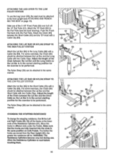
... exercises, the Chain (84) should be attached between the Short Cable (23) and the "S"-Hook with a Cable Clip (83). Make sure that the hooks are moved from the Rear Upright (82), the greater the resistance will be. ATTACHING THE LEG LEVER TO THE LOW PULLEY STATION To use . Attach the Chain (84) between the Lat Bar and the Short Cable with a Cable Clip (83). ATTACHING THE LAT BAR OR NYLON STRAP...
... exercises, the Chain (84) should be attached between the Short Cable (23) and the "S"-Hook with a Cable Clip (83). Make sure that the hooks are moved from the Rear Upright (82), the greater the resistance will be. ATTACHING THE LEG LEVER TO THE LOW PULLEY STATION To use . Attach the Chain (84) between the Lat Bar and the Short Cable with a Cable Clip (83). ATTACHING THE LAT BAR OR NYLON STRAP...
User Manual
Page 17
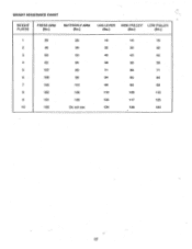
WEIGHT RESISTANCE CHART WEIGHT PLATES PRESS ARM (lbs.) BUTTERFLY ARM (lbs.) LEG LEVER HIGH PULLEY LOW PULLEY (lbs.) (lbs.) (lbs.) 1 29 26 18 16 18 2 48 39 32 30 32 3 69 50 45 43 45 4 83 64 58 56 58 5 107 80 71 68 71 6 129 96 84 80 84 7 145 112 98 93 98 8 163 130 110 105 110 9 181 149 125 117 125 10 183 Do not use 134 128 134 17
WEIGHT RESISTANCE CHART WEIGHT PLATES PRESS ARM (lbs.) BUTTERFLY ARM (lbs.) LEG LEVER HIGH PULLEY LOW PULLEY (lbs.) (lbs.) (lbs.) 1 29 26 18 16 18 2 48 39 32 30 32 3 69 50 45 43 45 4 83 64 58 56 58 5 107 80 71 68 71 6 129 96 84 80 84 7 145 112 98 93 98 8 163 130 110 105 110 9 181 149 125 117 125 10 183 Do not use 134 128 134 17
User Manual
Page 18
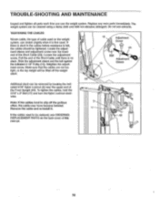
... the pulleys often, the cable may have become twisted. Loosen the adjustment screw. TIGHTENING THE CABLES Woven cable, the type of this manual. 18 Additional slack can be replaced, see ORDERING 42 REPLACEMENT PARTS on the back cover of cable used on the weight system, can stretch slightly when it . 15 Adjustment Screw 23 Ball Adjustment 15 Sleeve 23 3 1/ If the cables need to slip off the weight stack. Slide the adjustment sleeve...
... the pulleys often, the cable may have become twisted. Loosen the adjustment screw. TIGHTENING THE CABLES Woven cable, the type of this manual. 18 Additional slack can be replaced, see ORDERING 42 REPLACEMENT PARTS on the back cover of cable used on the weight system, can stretch slightly when it . 15 Adjustment Screw 23 Ball Adjustment 15 Sleeve 23 3 1/ If the cables need to slip off the weight stack. Slide the adjustment sleeve...

User Manual
Page 19
CABLE DIAGRAM The cable diagram below shows the proper routing of the Short Cable (23); The letters show the routing of the Long Cable (66). 2 4 8-Top Frame 7 3 6 0 5 Long Cable (66) High Pulley Station D Weight Tube • Short Cable (23) Low Pulley Station 19 the numbers show the routing of the Short Cable (23) and the Long Cable (66). Use the diagram to make sure that the two cables are assembled correctly.
CABLE DIAGRAM The cable diagram below shows the proper routing of the Short Cable (23); The letters show the routing of the Long Cable (66). 2 4 8-Top Frame 7 3 6 0 5 Long Cable (66) High Pulley Station D Weight Tube • Short Cable (23) Low Pulley Station 19 the numbers show the routing of the Short Cable (23) and the Long Cable (66). Use the diagram to make sure that the two cables are assembled correctly.
User Manual
Page 20
... OF REMOVAL, INSTALLATION OR OTHER CONSEQUENTIAL DAMAGES OF WHATSOEVER NATURE. until 6 p.m. The SERIAL NUMBER of the product (see the PART LIST/EXPLODED DRAWING attached at one of its authorized service centers. This warranty does not extend to any product or damage to a product caused by or attributable to state. No other rights which warranty claim is authorized by ICON. Printed in...
... OF REMOVAL, INSTALLATION OR OTHER CONSEQUENTIAL DAMAGES OF WHATSOEVER NATURE. until 6 p.m. The SERIAL NUMBER of the product (see the PART LIST/EXPLODED DRAWING attached at one of its authorized service centers. This warranty does not extend to any product or damage to a product caused by or attributable to state. No other rights which warranty claim is authorized by ICON. Printed in...
User Manual
Page 27
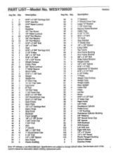
... Tube Weight Guide Rear Upright Cable Clip Chain Lat Bar Brace 5/16" x 3 1/2° Bolt 2° Outer Cap Right Pedal Left Pedal Resistance Cylinder Pedal Cover 1 1/2" Bushing Resistance Cylinder Bushing 5/8" Retainer 5/8" Round Cover Cap 5/8" Spacer VKR Backrest VKR Armrest Left VKR Arm Right VKR Arm 1/4" x 2" Screw 1/4" x 1/2" Screw Plastic Flanged Bushing Owner's Manual Exercise Poster Note: -fr indicates a non-illustrated part. See the back cover of the owner's manual for information about ordering replacement parts. Description Key No. PART LIST Model No. Qty. Specifications...
... Tube Weight Guide Rear Upright Cable Clip Chain Lat Bar Brace 5/16" x 3 1/2° Bolt 2° Outer Cap Right Pedal Left Pedal Resistance Cylinder Pedal Cover 1 1/2" Bushing Resistance Cylinder Bushing 5/8" Retainer 5/8" Round Cover Cap 5/8" Spacer VKR Backrest VKR Armrest Left VKR Arm Right VKR Arm 1/4" x 2" Screw 1/4" x 1/2" Screw Plastic Flanged Bushing Owner's Manual Exercise Poster Note: -fr indicates a non-illustrated part. See the back cover of the owner's manual for information about ordering replacement parts. Description Key No. PART LIST Model No. Qty. Specifications...


