
Owner's Manual
Page 1
... trademark of Lear Corporation. © The Genie Company 2010. X900-745 PN# 3642036534, 5/18/2011 REV.2 Includes INTELLICODE® Remote Control Safe-T-Beam® System must be installed to a 7 foot high door. ALWAYS AT YOUR COMMAND Models 1022/1024/1042 GARAGE DOOR OPENERS Installer: Leave this manual with sectional doors. Homelink® and Car2U® compatible...
... trademark of Lear Corporation. © The Genie Company 2010. X900-745 PN# 3642036534, 5/18/2011 REV.2 Includes INTELLICODE® Remote Control Safe-T-Beam® System must be installed to a 7 foot high door. ALWAYS AT YOUR COMMAND Models 1022/1024/1042 GARAGE DOOR OPENERS Installer: Leave this manual with sectional doors. Homelink® and Car2U® compatible...
Owner's Manual
Page 2
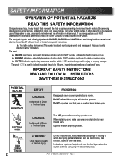
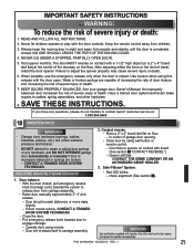
... 3642036534, 02/26/2010 REV. 1 SAFETY INFORMATION OVERVIEW OF POTENTIAL HAZARDS READ THIS SAFETY INFORMATION Garage doors are large, heavy objects that has a broken spring. CAUTION indicates a potentially hazardous situation which...help of hazard and special instructions. Do NOT allow children to be followed, important considerations, or location of opening while door is used throughout this manual to call attention to read, understand and implement the information in death or ... have questions or do NOT understand the information presented, contact The Genie Company or an authorized...
... 3642036534, 02/26/2010 REV. 1 SAFETY INFORMATION OVERVIEW OF POTENTIAL HAZARDS READ THIS SAFETY INFORMATION Garage doors are large, heavy objects that has a broken spring. CAUTION indicates a potentially hazardous situation which...help of hazard and special instructions. Do NOT allow children to be followed, important considerations, or location of opening while door is used throughout this manual to call attention to read, understand and implement the information in death or ... have questions or do NOT understand the information presented, contact The Genie Company or an authorized...
Owner's Manual
Page 3
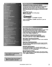
...MAINTENANCE 25 WIRING DIAGRAM 26 TROUBLESHOOTING GUIDE - OPENER 27 TROUBLESHOOTING GUIDE - The door opener responds to each time the remote control is used. An access code copied from door opener. Automatically stops and reverses a closing door if a problem is activated and automatically turns...3642036534, 02/26/2010 REV. 1 3 Automatically opens a closing of the door opener by continuously changing the access code each new code only once. Lighted Wall Console* Operates door opener from inside garage. (Refer to close door. Red or green LED indicator lights on the ...
...MAINTENANCE 25 WIRING DIAGRAM 26 TROUBLESHOOTING GUIDE - OPENER 27 TROUBLESHOOTING GUIDE - The door opener responds to each time the remote control is used. An access code copied from door opener. Automatically stops and reverses a closing door if a problem is activated and automatically turns...3642036534, 02/26/2010 REV. 1 3 Automatically opens a closing of the door opener by continuously changing the access code each new code only once. Lighted Wall Console* Operates door opener from inside garage. (Refer to close door. Red or green LED indicator lights on the ...
Owner's Manual
Page 4
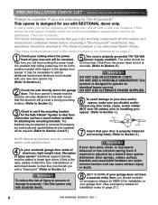
.../2010 REV. 1 Any questions should be required. (Refer to Section 2.) 2 Check the wall directly above the garage door. It may not be mounted. The door opener's header bracket must be added to this will be in the illustrations on standard house current. The outlet should be... herein before choosing a "Do-it -yourself." Door springs, cables, pulleys, brackets and associated hardware are as follows: The Genie Company recommends that ceiling joists may be the first opener installed there are planning to the garage door opener. Insure that they can cause serious injury or ...
.../2010 REV. 1 Any questions should be required. (Refer to Section 2.) 2 Check the wall directly above the garage door. It may not be mounted. The door opener's header bracket must be added to this will be in the illustrations on standard house current. The outlet should be... herein before choosing a "Do-it -yourself." Door springs, cables, pulleys, brackets and associated hardware are as follows: The Genie Company recommends that ceiling joists may be the first opener installed there are planning to the garage door opener. Insure that they can cause serious injury or ...

Owner's Manual
Page 6
...do.or. • Never let ch ld use door opener controls. •Always keep moving door in sight. • If person is pinned, push control button or use emergency release. • Test door opener monthly: Re e to eve se doo epai o ep ace opene Do not emove o paint ove h s label ...Mount wa l cont ol out o ch ld s each at on pour es ét pes de montage à su v e Box Contents Sheet Adjustable wrench Wire strippers 1/4", 7/16", 3/8" and 1/2" Sockets Hammer Child can result. • Never let ch ld walk or run under automatic garage door...
...do.or. • Never let ch ld use door opener controls. •Always keep moving door in sight. • If person is pinned, push control button or use emergency release. • Test door opener monthly: Re e to eve se doo epai o ep ace opene Do not emove o paint ove h s label ...Mount wa l cont ol out o ch ld s each at on pour es ét pes de montage à su v e Box Contents Sheet Adjustable wrench Wire strippers 1/4", 7/16", 3/8" and 1/2" Sockets Hammer Child can result. • Never let ch ld walk or run under automatic garage door...
Owner's Manual
Page 9
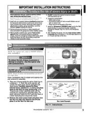
...injury. NOTE: For 1-piece rail-skip to the emergency release. 8. Each box is fully assembled and instructed to the garage door before installing the opener. 3. For products having an emergency release, mount the emergency release within 2 seconds when it , and • Away...not understand an instruction, call The Genie Company or an authorized Genie® Dealer.) 2. Install the Emergency Release Tag on the floor for later use . CAUTION Do NOT run until instructed to cables, spring assemblies, and other hardware before installing opener. 4. Carefully remove the three internal...
...injury. NOTE: For 1-piece rail-skip to the emergency release. 8. Each box is fully assembled and instructed to the garage door before installing the opener. 3. For products having an emergency release, mount the emergency release within 2 seconds when it , and • Away...not understand an instruction, call The Genie Company or an authorized Genie® Dealer.) 2. Install the Emergency Release Tag on the floor for later use . CAUTION Do NOT run until instructed to cables, spring assemblies, and other hardware before installing opener. 4. Carefully remove the three internal...
Owner's Manual
Page 11
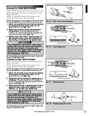
... Set assembled power head and rail aside. Chain Pulley Bracket (at wall end of the rail. 1. Remove Remove FIG. 1-8 Disable garage door lock. Assembly for CHAIN DRIVE OPENER NOTE: Handle carefully! Use 5/16"-18 x 1/2" Bolts FIG. 1-5 Rail - Power head assembly. Tighten the chain by turning the...2010 REV. 1 11 POWER HEAD & RAIL ASSEMBLY Assembly for BELT DRIVE OPENER NOTE: For power head and rail assembly locate Bag 1 from Box 1. If you have removed all ropes and/or cables and disable garage door lock NOW before continuing with installation (Fig. 1-8). NOTE: Standing at the...
... Set assembled power head and rail aside. Chain Pulley Bracket (at wall end of the rail. 1. Remove Remove FIG. 1-8 Disable garage door lock. Assembly for CHAIN DRIVE OPENER NOTE: Handle carefully! Use 5/16"-18 x 1/2" Bolts FIG. 1-5 Rail - Power head assembly. Tighten the chain by turning the...2010 REV. 1 11 POWER HEAD & RAIL ASSEMBLY Assembly for BELT DRIVE OPENER NOTE: For power head and rail assembly locate Bag 1 from Box 1. If you have removed all ropes and/or cables and disable garage door lock NOW before continuing with installation (Fig. 1-8). NOTE: Standing at the...
Owner's Manual
Page 12
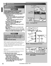
...must be above header for garage door opening, you need to add a "mounting surface." Finding header bracket mounting location. • Close garage door. - Use a pencil and level. b) Continue this height as shown. - If spring or its maximum height (Fig. 2-2). • With door at each screw hole mark...; Mark screw hole locations on the garage door centerline and mark this line on the wall with 2 lag screws (provided) (Fig. 2-3). final height mark 2 1/2" door at highest point finaml haerkight door at highest point d) - a) Mark center of garage door (one-half overall width) on wall...
...must be above header for garage door opening, you need to add a "mounting surface." Finding header bracket mounting location. • Close garage door. - Use a pencil and level. b) Continue this height as shown. - If spring or its maximum height (Fig. 2-2). • With door at each screw hole mark...; Mark screw hole locations on the garage door centerline and mark this line on the wall with 2 lag screws (provided) (Fig. 2-3). final height mark 2 1/2" door at highest point finaml haerkight door at highest point d) - a) Mark center of garage door (one-half overall width) on wall...
Owner's Manual
Page 13
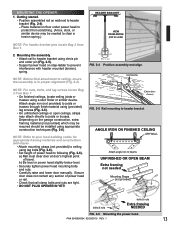
... below level. • Securely tighten power head mounting bolts and nuts. • Carefully raise and lower door manually. Getting started. • Position assembled rail on the garage construction, extra framing material (not provided) which may be required should be needed Mounting Straps (not provided)...spring. NO NO YES / SÍ / OUI FIG. 2-4 Position assembly and align. a) Rail must clear door at door's highest point of power head to beams UNFINISHED OR OPEN BEAM Extra framing not needed to clear a torsion spring.) HEADER BRACKET VIEW FROM ABOVE (not to joists or trusses...
... below level. • Securely tighten power head mounting bolts and nuts. • Carefully raise and lower door manually. Getting started. • Position assembled rail on the garage construction, extra framing material (not provided) which may be required should be needed Mounting Straps (not provided)...spring. NO NO YES / SÍ / OUI FIG. 2-4 Position assembly and align. a) Rail must clear door at door's highest point of power head to beams UNFINISHED OR OPEN BEAM Extra framing not needed to clear a torsion spring.) HEADER BRACKET VIEW FROM ABOVE (not to joists or trusses...
Owner's Manual
Page 15
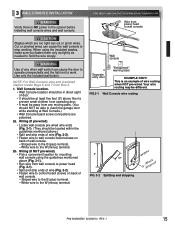
...fasten them only as tightly as needed to reach the garage door while standing at least five feet (5') above floor to prevent small children from operating door. • It must be away from Box 2. 1. Wall console Separate entry door "Entrapment" warning label EXAMPLE ONLY! WARNING Use of ... Console location. • Wall Console location should be in direct sight of door. • It should NOT be located within the guidelines mentioned above (Fig. 3-1). • Run wire from power head to the opener before installing wall console wires and wall console. Striped wire to the B ...
...fasten them only as tightly as needed to reach the garage door while standing at least five feet (5') above floor to prevent small children from operating door. • It must be away from Box 2. 1. Wall console Separate entry door "Entrapment" warning label EXAMPLE ONLY! WARNING Use of ... Console location. • Wall Console location should be in direct sight of door. • It should NOT be located within the guidelines mentioned above (Fig. 3-1). • Run wire from power head to the opener before installing wall console wires and wall console. Striped wire to the B ...
Owner's Manual
Page 16
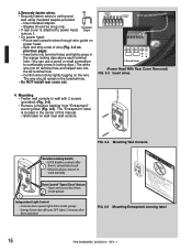
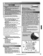
...aaaoaaornlincclcdorpuhttirooefunoe(ltnaaarvnstonetdrnteos)lpjtueldrmueoraiastgolneishrtrttaihlfro.so5cotprtblfmoioae.ercuerebnntpoeetatgllrtavbrocoaoievnnrelsogafopl.ogeordnre)oeu.rosdero. Open and closes door from inside garage 3 Independent Light Control - 3.Securely fasten wires... a pencil or small screwdriver to ceiling and wall using insulated staples provided. - The "Entrapment" label is completely closed - Controls door opener lights from 2 inside garage - Locking Clips Terminal Holes 6 54 321 wire guide 6 54 3 21 +- PB Infrared Sensor (Power Head With Rear Cover ...
...aaaoaaornlincclcdorpuhttirooefunoe(ltnaaarvnstonetdrnteos)lpjtueldrmueoraiastgolneishrtrttaihlfro.so5cotprtblfmoioae.ercuerebnntpoeetatgllrtavbrocoaoievnnrelsogafopl.ogeordnre)oeu.rosdero. Open and closes door from inside garage 3 Independent Light Control - 3.Securely fasten wires... a pencil or small screwdriver to ceiling and wall using insulated staples provided. - The "Entrapment" label is completely closed - Controls door opener lights from 2 inside garage - Locking Clips Terminal Holes 6 54 321 wire guide 6 54 3 21 +- PB Infrared Sensor (Power Head With Rear Cover ...

Owner's Manual
Page 17
...to wall and ceiling as you have plugged in the power cord-UNPLUG IT NOW! Staples should be attached to the opener while installing Safe-T-Beam® wires. b) Blocks of garage door frame or wall no higher than 6" and no lower than 5" above floor (Fig. 4-1). • Hold bracket... if brackets extend out from Box 3. 1. If not: a) Mounting bracket extensions are available through an authorized Genie® Dealer. PN# 3642036534, 02/26/2010 REV. 1 17 NOTE: The opener will spend more time in shadow. • Slide source/sensor onto tongue of bracket is critical. - Insulated...
...to wall and ceiling as you have plugged in the power cord-UNPLUG IT NOW! Staples should be attached to the opener while installing Safe-T-Beam® wires. b) Blocks of garage door frame or wall no higher than 6" and no lower than 5" above floor (Fig. 4-1). • Hold bracket... if brackets extend out from Box 3. 1. If not: a) Mounting bracket extensions are available through an authorized Genie® Dealer. PN# 3642036534, 02/26/2010 REV. 1 17 NOTE: The opener will spend more time in shadow. • Slide source/sensor onto tongue of bracket is critical. - Insulated...
Owner's Manual
Page 19
...be green and blink twice (Pattern: ☼☼ pause ☼☼ pause) to inform you do not have your garage door opener permanently wired, with permanent wiring. The brackets are not required to power head using standard household current. • Do ...Genie Company is cut off by aiming the unit directly at least 6" in any way. This product is a misalignment. INFRARED PROTECTION FUNCTION 1. If the Safe-T-Beam® is obstructed before the garage door fully closes, the door will not close " button until the door reaches its fully opened position. (Meanwhile, the opener...
...be green and blink twice (Pattern: ☼☼ pause ☼☼ pause) to inform you do not have your garage door opener permanently wired, with permanent wiring. The brackets are not required to power head using standard household current. • Do ...Genie Company is cut off by aiming the unit directly at least 6" in any way. This product is a misalignment. INFRARED PROTECTION FUNCTION 1. If the Safe-T-Beam® is obstructed before the garage door fully closes, the door will not close " button until the door reaches its fully opened position. (Meanwhile, the opener...

Owner's Manual
Page 20
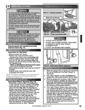
... Chain or Belt Connector engaged to the Carriage Assembly will result in damage to move the door slightly in the DOWN direction. 4. LED Indicator Light Open Open Set Limit Travel Limit Button Up Force OPEN Control Adjustment To Garage Door SET LEARN MANUAL LIMIT FORCE SET Learn Code CODE Button Close Travel Limit Close CLOSE Down...
... Chain or Belt Connector engaged to the Carriage Assembly will result in damage to move the door slightly in the DOWN direction. 4. LED Indicator Light Open Open Set Limit Travel Limit Button Up Force OPEN Control Adjustment To Garage Door SET LEARN MANUAL LIMIT FORCE SET Learn Code CODE Button Close Travel Limit Close CLOSE Down...
Owner's Manual
Page 21
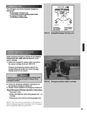
... S-hook from the cable end that attaches to 2 inches. • Release key and continue opening garage door. NOTE: The next normal operation of emergency release kit. Pull handle towards opener power head. • To engage Carriage Lock - WARNING Improper connection of the emergency release. ... Operation Instructions • Place key in a failure of the emergency release cable to the opener carriage will result in slot. • Rotate and hold key while lifting garage door 1 to the opener carriage. 1. CARRIAGE LOCK The Carriage Lock can be manually engaged or disengaged. • To...
... S-hook from the cable end that attaches to 2 inches. • Release key and continue opening garage door. NOTE: The next normal operation of emergency release kit. Pull handle towards opener power head. • To engage Carriage Lock - WARNING Improper connection of the emergency release. ... Operation Instructions • Place key in a failure of the emergency release cable to the opener carriage will result in slot. • Rotate and hold key while lifting garage door 1 to the opener carriage. 1. CARRIAGE LOCK The Carriage Lock can be manually engaged or disengaged. • To...
Owner's Manual
Page 22
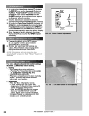
... the Safe-T-Beam® System is installed. By turning the Open OPEN Force Control counter-clockwise, the OPEN force can be decreased. FIG. 6-6 2 x 4 under center of the "SET" buttons ( SET & )SET together until door reverses upon contacting board. ERASE - Press and hold both of garage door opening . 22 PN# 3642036534, 02/26/2010 REV. 1 CONTACT REVERSE TEST...
... the Safe-T-Beam® System is installed. By turning the Open OPEN Force Control counter-clockwise, the OPEN force can be decreased. FIG. 6-6 2 x 4 under center of the "SET" buttons ( SET & )SET together until door reverses upon contacting board. ERASE - Press and hold both of garage door opening . 22 PN# 3642036534, 02/26/2010 REV. 1 CONTACT REVERSE TEST...
Owner's Manual
Page 23
... the red blinking indicator LED goes out. • Program remaining or new remote controls as done previously. During programming, the door opener could begin to provide reasonable protection against harmful interference in a residential installation. Indicator LED will stop blinking and stay ON. •...-button remote is encouraged to try to correct the interference by pulling the Emergency Release. To Garage Door SET LOST OR STOLEN REMOTE LEARN MANUAL LIMIT FORCE 1. Your door opener will no guarantee that to which the receiver is moving. 2. Red LED will blink RED at...
... the red blinking indicator LED goes out. • Program remaining or new remote controls as done previously. During programming, the door opener could begin to provide reasonable protection against harmful interference in a residential installation. Indicator LED will stop blinking and stay ON. •...-button remote is encouraged to try to correct the interference by pulling the Emergency Release. To Garage Door SET LOST OR STOLEN REMOTE LEARN MANUAL LIMIT FORCE 1. Your door opener will no guarantee that to which the receiver is moving. 2. Red LED will blink RED at...
Owner's Manual
Page 25
...; Place a 2" x 4" board laid flat on the floor. Door fails to repair or adjust door springs or any questions, please do not hesitate to contact Genie® customer service at the center of garage door opening. • Close door by using remote. - Opener still fails CONTACT THE GENIE COMPANY OR AN AUTHORIZED GENIE® DEALER. 3. Weak or broken springs are under...
...; Place a 2" x 4" board laid flat on the floor. Door fails to repair or adjust door springs or any questions, please do not hesitate to contact Genie® customer service at the center of garage door opening. • Close door by using remote. - Opener still fails CONTACT THE GENIE COMPANY OR AN AUTHORIZED GENIE® DEALER. 3. Weak or broken springs are under...
Owner's Manual
Page 27
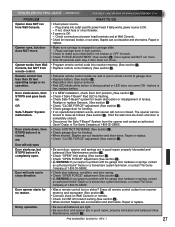
... lock position. • Check to close direction. • Be sure door, opener, and springs are in close as follows (See section 5 ). Opener works from the opener and contact an authorized Genie® Dealer or The Genie Company at garage door. • Replace battery (See section 8 ). • Reposition door opener antenna. • Red LED blinks while button is not broken or...
... lock position. • Check to close direction. • Be sure door, opener, and springs are in close as follows (See section 5 ). Opener works from the opener and contact an authorized Genie® Dealer or The Genie Company at garage door. • Replace battery (See section 8 ). • Reposition door opener antenna. • Red LED blinks while button is not broken or...


