
Owner's Manual
Page 1
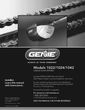
...# 3642036534, 5/18/2011 REV.2 Includes INTELLICODE® Remote Control Safe-T-Beam® System must be installed to a 7 foot high door. ALWAYS AT YOUR COMMAND Models 1022/1024/1042 GARAGE DOOR OPENERS Installer: Leave this manual with sectional doors. For use only with homeowner. Homelink® is standard for up to close door. Your Residential Opener comes with a Rail Assembly which is a registered trademark of Lear Corporation. © The Genie Company 2010.
...# 3642036534, 5/18/2011 REV.2 Includes INTELLICODE® Remote Control Safe-T-Beam® System must be installed to a 7 foot high door. ALWAYS AT YOUR COMMAND Models 1022/1024/1042 GARAGE DOOR OPENERS Installer: Leave this manual with sectional doors. For use only with homeowner. Homelink® is standard for up to close door. Your Residential Opener comes with a Rail Assembly which is a registered trademark of Lear Corporation. © The Genie Company 2010.
Owner's Manual
Page 2
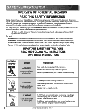
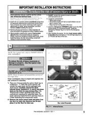
... is moving. Do NOT operate a door that jams or one that move with the door operator. SAFETY INFORMATION OVERVIEW OF POTENTIAL HAZARDS READ THIS SAFETY INFORMATION Garage doors are not pinched or near moving parts. Since moving objects, springs under tension, and electric motors can cause injuries, your safety and the safety of others depend on the owner or user of springs under high tension and electric motors. WARNING indicates a potentially...
... is moving. Do NOT operate a door that jams or one that move with the door operator. SAFETY INFORMATION OVERVIEW OF POTENTIAL HAZARDS READ THIS SAFETY INFORMATION Garage doors are not pinched or near moving parts. Since moving objects, springs under tension, and electric motors can cause injuries, your safety and the safety of others depend on the owner or user of springs under high tension and electric motors. WARNING indicates a potentially...
Owner's Manual
Page 3
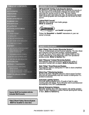
.... Lighted Wall Console* Operates door opener from inside garage. (Refer to Section 6.) Safe-T-Stop® Timed Reversed System. TABLE OF CONTENTS SECTION PAGE SAFETY INFORMATION 2 OPENER FEATURES 3 SAFETY FEATURES 3 PRE-INSTALLATION CHECK LIST 4-5 RECOMMENDED TOOLS 6 PARTS IDENTIFICATION 6-7 KEY ILLUSTRATIONS 8 SAFETY INSTALLATION INFORMATION 9 INSTALLATION 1 OPENER ASSEMBLY 9-11 2 INSTALLATION 12-14 3 WALL BUTTON INSTALLATION 15-16 4 SAFE-T-BEAM® SYSTEM INSTALLATION 17-18 5 CONNECTING TO POWER 19 ADJUSTMENTS 6 LIMIT SWITCHES & FORCE ADJUSTMENT 20-22 KEYED EMERGENCY...
.... Lighted Wall Console* Operates door opener from inside garage. (Refer to Section 6.) Safe-T-Stop® Timed Reversed System. TABLE OF CONTENTS SECTION PAGE SAFETY INFORMATION 2 OPENER FEATURES 3 SAFETY FEATURES 3 PRE-INSTALLATION CHECK LIST 4-5 RECOMMENDED TOOLS 6 PARTS IDENTIFICATION 6-7 KEY ILLUSTRATIONS 8 SAFETY INSTALLATION INFORMATION 9 INSTALLATION 1 OPENER ASSEMBLY 9-11 2 INSTALLATION 12-14 3 WALL BUTTON INSTALLATION 15-16 4 SAFE-T-BEAM® SYSTEM INSTALLATION 17-18 5 CONNECTING TO POWER 19 ADJUSTMENTS 6 LIMIT SWITCHES & FORCE ADJUSTMENT 20-22 KEYED EMERGENCY...
Owner's Manual
Page 4
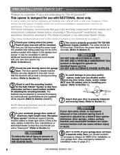
...: Mounting brackets must be installed within code specifications. 4 Is your sectional garage door made of your new unit will provide a strong mounting location. (Refer to Section 2.) 3 Check to see if the mounting location for use with your door is mounted. (Refer to this wall. DO NOT USE ALTERNATE POWER SUPPLIES. 6 To avoid damage to your door and/or opener, make sure you disable and/or remove any door locks, ropes, and/or cables (NOT door lift...
...: Mounting brackets must be installed within code specifications. 4 Is your sectional garage door made of your new unit will provide a strong mounting location. (Refer to Section 2.) 3 Check to see if the mounting location for use with your door is mounted. (Refer to this wall. DO NOT USE ALTERNATE POWER SUPPLIES. 6 To avoid damage to your door and/or opener, make sure you disable and/or remove any door locks, ropes, and/or cables (NOT door lift...

Owner's Manual
Page 6
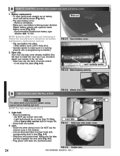
... opene Do not emove o paint ove h s label Mount wa l cont ol out o ch ld s each at east 5 eet above loo ) ace next o wall cont ol © 999 Entrapment Warning Label Header Bracket Safe-T-Beam® Source with wire (Red LED) Safe-T-Beam® Sensor with wire (Green LED) Wire Door Bracket Three-button Remote Control Safe-T-Beam® Source/Sensor Bracket Insulated Staple Rail Section Clamp Door Arm Wall Console End Rail Section Center Rail Section Pro Rail (Chain) Section OR Head Rail (Chain) Section Pro Rail (Belt) Section Head Rail (Belt...
... opene Do not emove o paint ove h s label Mount wa l cont ol out o ch ld s each at east 5 eet above loo ) ace next o wall cont ol © 999 Entrapment Warning Label Header Bracket Safe-T-Beam® Source with wire (Red LED) Safe-T-Beam® Sensor with wire (Green LED) Wire Door Bracket Three-button Remote Control Safe-T-Beam® Source/Sensor Bracket Insulated Staple Rail Section Clamp Door Arm Wall Console End Rail Section Center Rail Section Pro Rail (Chain) Section OR Head Rail (Chain) Section Pro Rail (Belt) Section Head Rail (Belt...
Owner's Manual
Page 9
... OPERATION INSTRUCTIONS. (If you have questions or do so. 6. An improperly balanced door could cause severe injury. Remove all ropes and remove or make repairs or adjustments to source of 5 feet so small children are 4 boxes inside . 2. Do NOT connect the opener to cables, spring assemblies, and other hardware before installing opener. 4. Locate the control button: • Within sight of door, • At minimum height of power until opener is numbered...
... OPERATION INSTRUCTIONS. (If you have questions or do so. 6. An improperly balanced door could cause severe injury. Remove all ropes and remove or make repairs or adjustments to source of 5 feet so small children are 4 boxes inside . 2. Do NOT connect the opener to cables, spring assemblies, and other hardware before installing opener. 4. Locate the control button: • Within sight of door, • At minimum height of power until opener is numbered...
Owner's Manual
Page 11
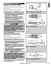
... lock already. Remove Remove FIG. 1-8 Disable garage door lock. Assembly for CHAIN DRIVE OPENER NOTE: Handle carefully! Use (3) bolts, 5/16"-18 x 1/2" (Fig. 1-5). 2. Belt Pulley Bracket (at center of the rail. 1. NOTE: Copy serial number from power head frame and record it on warranty page. Attach rail assembly to move pulley this direction Chain Chain 1/8" T-Rail at wall end of rail) Use 1/2" socket on the rail (Fig. 1-6). Begin with Section 2 INSTALLATION. Drive chain can slide out of rail assembly T-Rail FIG. 1-7 Belt adjustment. Attach rail assembly...
... lock already. Remove Remove FIG. 1-8 Disable garage door lock. Assembly for CHAIN DRIVE OPENER NOTE: Handle carefully! Use (3) bolts, 5/16"-18 x 1/2" (Fig. 1-5). 2. Belt Pulley Bracket (at center of the rail. 1. NOTE: Copy serial number from power head frame and record it on warranty page. Attach rail assembly to move pulley this direction Chain Chain 1/8" T-Rail at wall end of rail) Use 1/2" socket on the rail (Fig. 1-6). Begin with Section 2 INSTALLATION. Drive chain can slide out of rail assembly T-Rail FIG. 1-7 Belt adjustment. Attach rail assembly...
Owner's Manual
Page 13
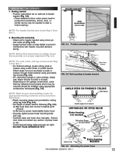
... material using clevis pin and cotter pin (Fig. 2-5). • Support power head on wall next to beams UNFINISHED OR OPEN BEAM Extra framing not needed to clear a torsion spring.) HEADER BRACKET VIEW FROM ABOVE (not to prevent interference with header mounted (torsion) spring. Depending on floor under power head to following (Fig. 2-6). CLEVIS PIN COTTER PIN NOTE: For nuts, bolts, and lag screws locate Bag 3 from Box 1. 2. Ensure door does...
... material using clevis pin and cotter pin (Fig. 2-5). • Support power head on wall next to beams UNFINISHED OR OPEN BEAM Extra framing not needed to clear a torsion spring.) HEADER BRACKET VIEW FROM ABOVE (not to prevent interference with header mounted (torsion) spring. Depending on floor under power head to following (Fig. 2-6). CLEVIS PIN COTTER PIN NOTE: For nuts, bolts, and lag screws locate Bag 3 from Box 1. 2. Ensure door does...
Owner's Manual
Page 15
... wall control can cause the wall console to the B (plus ) terminal. - This is NO power to the B (plus ) terminal. - White wire to wall console. Striped wire to the opener before installing wall console wires and wall console. Wall Console location. • Wall Console location should be different. Your wire routing may be at Wall Console.) • Wall Console board screw connections are too tight can cut or pinch wires. Use only the included wall button. When using the guidelines mentioned above (Fig. 3-1). • Run wire from Box...
... wall control can cause the wall console to the B (plus ) terminal. - This is NO power to the B (plus ) terminal. - White wire to wall console. Striped wire to the opener before installing wall console wires and wall console. Wall Console location. • Wall Console location should be different. Your wire routing may be at Wall Console.) • Wall Console board screw connections are too tight can cut or pinch wires. Use only the included wall button. When using the guidelines mentioned above (Fig. 3-1). • Run wire from Box...
Owner's Manual
Page 16
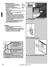
... only. Energy-Saver shut-off turns OFF lights 3 minutes after 1 door is attached to work normally Door Control "Open/Close" Button - Split and strip ends of this manual. - Locking Clips Terminal Holes 6 54 321 wire guide 6 54 3 21 +- Mounting. • Fasten wall console to ceiling and wall using insulated staples provided. - FIG. 3-4 Mounting Wall Console. Insulated • If rear cover is completely closed - PB Infrared Sensor (Power Head With Rear Cover Removed) FIG. 3-3 Insert wires. 4. LOCK disables controls after door activation FIG...
... only. Energy-Saver shut-off turns OFF lights 3 minutes after 1 door is attached to work normally Door Control "Open/Close" Button - Split and strip ends of this manual. - Locking Clips Terminal Holes 6 54 321 wire guide 6 54 3 21 +- Mounting. • Fasten wall console to ceiling and wall using insulated staples provided. - FIG. 3-4 Mounting Wall Console. Insulated • If rear cover is completely closed - PB Infrared Sensor (Power Head With Rear Cover Removed) FIG. 3-3 Insert wires. 4. LOCK disables controls after door activation FIG...

Owner's Manual
Page 17
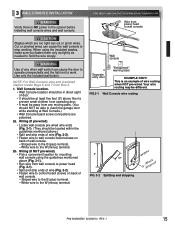
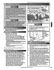
... from Box 3. 1. Red LED should always be attached to the opener while installing Safe-T-Beam® wires. 4 AFE-T-BEAM® SYSTEM INSTALLATION FOR HELP-1.800.354.3643 OR WWW.GENIECOMPANY.COM WARNING There should be snug only. ckets RED LED GREEN LED GREEN LED RED RED LED LED GREEN LED ONE DOOR GARAGE TWO DOOR GARAGE GREEN LED RED RED LED LED GREEN GREEN LED LED RED LED THREE DOOR GARAGE FIG. 4-4 Safe-T-Beam® source and sensor locations. Staples should be no further out from the wall, where it clicks into place (Fig. 4-3). Red Green 3a...
... from Box 3. 1. Red LED should always be attached to the opener while installing Safe-T-Beam® wires. 4 AFE-T-BEAM® SYSTEM INSTALLATION FOR HELP-1.800.354.3643 OR WWW.GENIECOMPANY.COM WARNING There should be snug only. ckets RED LED GREEN LED GREEN LED RED RED LED LED GREEN LED ONE DOOR GARAGE TWO DOOR GARAGE GREEN LED RED RED LED LED GREEN GREEN LED LED RED LED THREE DOOR GARAGE FIG. 4-4 Safe-T-Beam® source and sensor locations. Staples should be no further out from the wall, where it clicks into place (Fig. 4-3). Red Green 3a...
Owner's Manual
Page 19
... the Green LED sensor. Remove four motor cover screws (Fig. 5-2). • Remove existing power cord and strain relief from circuit. • Remove rear cover and motor cover. - DO NOT alter the plug in path between 5" - 6" above the floor (Fig. 5-4). FIG. 5-1 Connect to install one. NOTE: The Genie Company is installed improperly, you do not have to be adjusted slightly if needed. • Adjust the Red LED source by people or obstacle, the garage door will reverse...
... the Green LED sensor. Remove four motor cover screws (Fig. 5-2). • Remove existing power cord and strain relief from circuit. • Remove rear cover and motor cover. - DO NOT alter the plug in path between 5" - 6" above the floor (Fig. 5-4). FIG. 5-1 Connect to install one. NOTE: The Genie Company is installed improperly, you do not have to be adjusted slightly if needed. • Adjust the Red LED source by people or obstacle, the garage door will reverse...

Owner's Manual
Page 20
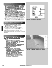
...Open Open Set Limit Travel Limit Button Up Force OPEN Control Adjustment To Garage Door SET LEARN MANUAL LIMIT FORCE SET Learn Code CODE Button Close Travel Limit Close CLOSE Down Force Set Limit Control Button Adjustment FIG. 6-1 Limit controls. This stores the closed position in the desired position, press and release the "Open SET Limit" SET button for 5 seconds. Hold the "Open Travel Limit" button until the chain or belt connector advances and engages to the Carriage Assembly (FIG 6-2). The LED indicator light will blink green once. CAUTION Operation of door...
...Open Open Set Limit Travel Limit Button Up Force OPEN Control Adjustment To Garage Door SET LEARN MANUAL LIMIT FORCE SET Learn Code CODE Button Close Travel Limit Close CLOSE Down Force Set Limit Control Button Adjustment FIG. 6-1 Limit controls. This stores the closed position in the desired position, press and release the "Open SET Limit" SET button for 5 seconds. Hold the "Open Travel Limit" button until the chain or belt connector advances and engages to the Carriage Assembly (FIG 6-2). The LED indicator light will blink green once. CAUTION Operation of door...
Owner's Manual
Page 22
... force adjustments and limit switch settings MUST BE COMPLETED before hitting board. - Testing. • Open garage door using wall button. • When door contacts board, the door must stop (within 2 seconds) and reverse direction returning to open door without reversing. 2. Check to reprogram close the door automatically unless the Safe-T-Beam® System is selected, this stores the maximum force level for the OPEN direction in memory. Repeat as necessary until the green indicator light blinks (about 5 seconds). 2. By turning the Close Force Control...
... force adjustments and limit switch settings MUST BE COMPLETED before hitting board. - Testing. • Open garage door using wall button. • When door contacts board, the door must stop (within 2 seconds) and reverse direction returning to open door without reversing. 2. Check to reprogram close the door automatically unless the Safe-T-Beam® System is selected, this stores the maximum force level for the OPEN direction in memory. Repeat as necessary until the green indicator light blinks (about 5 seconds). 2. By turning the Close Force Control...
Owner's Manual
Page 23
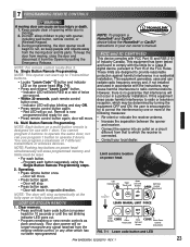
...stop blinking and stay ON. • Press remote control button again. - Multi Button Remote Programming. SET Learn Code CODE Button Close Travel Limit Close CLOSE Down Force Set Limit Control Button Adjustment FIG. 7-1 Learn code button and LED PN# 3642036534, 02/26/2010 REV. 1 23 Door will blink RED at the fully open or fully closed position. These limits are designed to comply with opener, including wall button, remote control, or Wireless Keypad. 3. Operating. • Press remote button once. - During programming, the door opener could begin to Part...
...stop blinking and stay ON. • Press remote control button again. - Multi Button Remote Programming. SET Learn Code CODE Button Close Travel Limit Close CLOSE Down Force Set Limit Control Button Adjustment FIG. 7-1 Learn code button and LED PN# 3642036534, 02/26/2010 REV. 1 23 Door will blink RED at the fully open or fully closed position. These limits are designed to comply with opener, including wall button, remote control, or Wireless Keypad. 3. Operating. • Press remote button once. - During programming, the door opener could begin to Part...
Owner's Manual
Page 24
... you choose to attach your remote to make sure it clicks shut. • Operate remote to the car visor. • Slide visor clip into back of remote control. - Slide out FIG. 8-1 Open battery cover. - Use a heavy duty service bulb for battery maintenance, replacement, and use. • Slip new battery into electrical outlet. Battery replacement. • To open gently push straight out on power head with symbols inside battery cover) (Fig. 8-2). - WARNING For added safety and protection please unplug opener before installing light bulb.
... you choose to attach your remote to make sure it clicks shut. • Operate remote to the car visor. • Slide visor clip into back of remote control. - Slide out FIG. 8-1 Open battery cover. - Use a heavy duty service bulb for battery maintenance, replacement, and use. • Slip new battery into electrical outlet. Battery replacement. • To open gently push straight out on power head with symbols inside battery cover) (Fig. 8-2). - WARNING For added safety and protection please unplug opener before installing light bulb.
Owner's Manual
Page 25
...; Close the door. • Pull emergency release knob towards the opener to carriage assembly. • Red LED blinks. - check alignment (See section 5 ). READ AND FOLLOW ALL INSTRUCTIONS. 2. Keep the remote control away from carriage assembly. • Raise door manually approximately 3'- 4' and release. - Any other hardware. 8. IMPORTANT SAFETY INSTRUCTIONS WARNING: To reduce the risk of garage door opening. • Close door by using wall button or remote control. - NO ONE SHOULD CROSS THE PATH OF THE MOVING DOOR. 4. Door fails to contact Genie® customer service...
...; Close the door. • Pull emergency release knob towards the opener to carriage assembly. • Red LED blinks. - check alignment (See section 5 ). READ AND FOLLOW ALL INSTRUCTIONS. 2. Keep the remote control away from carriage assembly. • Raise door manually approximately 3'- 4' and release. - Any other hardware. 8. IMPORTANT SAFETY INSTRUCTIONS WARNING: To reduce the risk of garage door opening. • Close door by using wall button or remote control. - NO ONE SHOULD CROSS THE PATH OF THE MOVING DOOR. 4. Door fails to contact Genie® customer service...
Owner's Manual
Page 27
... Plug a lamp into receiver memory (See section 7 ). Opener runs, but door does NOT move . Console, but STOPS before it 's completely open . OR Safe-T-Beam® System malfunction. • If a NEW installation, check Door Arm position, (See section 2 ). • Check if Safe-T-Beam® Red LED is low, replace battery. Staples can be forced to carriage slide. - Door opener starts for reversed, broken, or cut insulation and short wires. Noisy operation. • Be sure all remote control codes from the opener...
... Plug a lamp into receiver memory (See section 7 ). Opener runs, but door does NOT move . Console, but STOPS before it 's completely open . OR Safe-T-Beam® System malfunction. • If a NEW installation, check Door Arm position, (See section 2 ). • Check if Safe-T-Beam® Red LED is low, replace battery. Staples can be forced to carriage slide. - Door opener starts for reversed, broken, or cut insulation and short wires. Noisy operation. • Be sure all remote control codes from the opener...

Owner's Manual
Page 28
...) 3 BLINKS, Pause (Repeat) 4 BLINKS, Pause (Repeat) 5 BLINKS, Pause (Repeat) • Programming incomplete • Wire to power head or wire connection at 1-800-35-GENIE • Reverse wire placement in power head connector. • Check wall console and wiring. Repair or replace wall console and/or wiring. - NOTE: The 5 BLINKS pattern will remain blinking until Thermal Protector cools and resets. Staples can cut insulation and shorts wires. Contact Genie® authorized dealer for obstruction, remove. - Check door spring - If...
...) 3 BLINKS, Pause (Repeat) 4 BLINKS, Pause (Repeat) 5 BLINKS, Pause (Repeat) • Programming incomplete • Wire to power head or wire connection at 1-800-35-GENIE • Reverse wire placement in power head connector. • Check wall console and wiring. Repair or replace wall console and/or wiring. - NOTE: The 5 BLINKS pattern will remain blinking until Thermal Protector cools and resets. Staples can cut insulation and shorts wires. Contact Genie® authorized dealer for obstruction, remove. - Check door spring - If...

Owner's Manual
Page 30
... Act PURCHASER: INSTALLATION ADDRESS: DATE PURCHASED: OPENER MODEL: REMOTE CONTROL MODEL: DEALER NAME: DEALER ADDRESS: SERIAL NUMBER: P900-775 Seller warrants all other parts and components for a period of ONE (1) YEAR Seller's obligation under this warranty must be made promptly after discovery and within the applicable warranty period To obtain warranty service, you must contact Genie® customer service and provide proof...
... Act PURCHASER: INSTALLATION ADDRESS: DATE PURCHASED: OPENER MODEL: REMOTE CONTROL MODEL: DEALER NAME: DEALER ADDRESS: SERIAL NUMBER: P900-775 Seller warrants all other parts and components for a period of ONE (1) YEAR Seller's obligation under this warranty must be made promptly after discovery and within the applicable warranty period To obtain warranty service, you must contact Genie® customer service and provide proof...


