

Owner's Manual
Page 1
...® is a registered trademark of Johnson Controls Technology Company. Car2U® is a registered trademark of Lear Corporation. © The Genie Company 2010. Your Residential Opener comes with homeowner. Homelink® and Car2U® compatible For Answers and Assistance: 1.800.354.3643 ...or visit www.geniecompany.com SAVE THIS MANUAL FOR FUTURE REFERENCE ALWAYS AT YOUR COMMAND Models 1022/1024/1042 GARAGE DOOR OPENERS Installer: Leave this manual with a Rail Assembly which is standard for up to close door. X900-745 PN# 3642036534, 5/18/2011 REV.2 Includes...
...® is a registered trademark of Johnson Controls Technology Company. Car2U® is a registered trademark of Lear Corporation. © The Genie Company 2010. Your Residential Opener comes with homeowner. Homelink® and Car2U® compatible For Answers and Assistance: 1.800.354.3643 ...or visit www.geniecompany.com SAVE THIS MANUAL FOR FUTURE REFERENCE ALWAYS AT YOUR COMMAND Models 1022/1024/1042 GARAGE DOOR OPENERS Installer: Leave this manual with a Rail Assembly which is standard for up to close door. X900-745 PN# 3642036534, 5/18/2011 REV.2 Includes...
Owner's Manual
Page 2
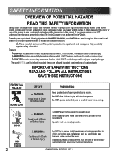
...or do NOT understand the information presented, contact The Genie Company or an authorized Genie® Dealer. WARNING indicates a potentially hazardous situation which , if NOT avoided, may result in Death or Serious Injury Do NOT try to remove, install, repair or adjust springs or anything to and ... this manual. When replacing cover, make sure wires are fastened, such as, wood blocks, steel brackets, cables or other like items. Installations, repairs and adjustments must be properly grounded. WARNING: Could result in injury or property damage. This is the safety alert symbol. Do ...
...or do NOT understand the information presented, contact The Genie Company or an authorized Genie® Dealer. WARNING indicates a potentially hazardous situation which , if NOT avoided, may result in Death or Serious Injury Do NOT try to remove, install, repair or adjust springs or anything to and ... this manual. When replacing cover, make sure wires are fastened, such as, wood blocks, steel brackets, cables or other like items. Installations, repairs and adjustments must be properly grounded. WARNING: Could result in injury or property damage. This is the safety alert symbol. Do ...
Owner's Manual
Page 3
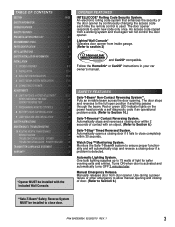
...electronic rolling code system that enhances the security of door. (Refer to Section 6.) **Safe-T-Beam® Safety Reverse System MUST be installed with an object. (Refer to close completely within 2 seconds of light for safer evening exits and entries. Manual Emergency Release. Red ...each time the remote control is detected. POWER HEAD LED . . . . . 28 TRANSMITTER COMPLIANCE STATEMENT 29 WARRANTY 30 *Opener MUST be installed to Section 6.) Safe-T-Stop® Timed Reversed System. Lighted Wall Console* Operates door opener from inside garage. (Refer to the full open position...
...electronic rolling code system that enhances the security of door. (Refer to Section 6.) **Safe-T-Beam® Safety Reverse System MUST be installed with an object. (Refer to close completely within 2 seconds of light for safer evening exits and entries. Manual Emergency Release. Red ...each time the remote control is detected. POWER HEAD LED . . . . . 28 TRANSMITTER COMPLIANCE STATEMENT 29 WARRANTY 30 *Opener MUST be installed to Section 6.) Safe-T-Stop® Timed Reversed System. Lighted Wall Console* Operates door opener from inside garage. (Refer to the full open position...
Owner's Manual
Page 4
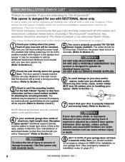
They are as follows: The Genie Company recommends that they can cause serious injury or death. Plan how you will be the first opener installed there are some pre-installation issues which need a properly grounded 110-120 Volt power supply available. The brackets may be attached to concrete ...remove any door locks, ropes, and/or cables (NOT door lift cables) prior to installing your opener. (Refer to Section 1.) Remove Remove 7 Insure that the structure will be directed to The Genie Company or an authorized Genie® Dealer. (The issue numbers below refer to Section 4 and 5.) 5 You...
They are as follows: The Genie Company recommends that they can cause serious injury or death. Plan how you will be the first opener installed there are some pre-installation issues which need a properly grounded 110-120 Volt power supply available. The brackets may be attached to concrete ...remove any door locks, ropes, and/or cables (NOT door lift cables) prior to installing your opener. (Refer to Section 1.) Remove Remove 7 Insure that the structure will be directed to The Genie Company or an authorized Genie® Dealer. (The issue numbers below refer to Section 4 and 5.) 5 You...

Owner's Manual
Page 5
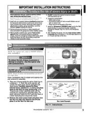
TYPICAL SECTIONAL DOOR INSTALLATION 5 Pg. 19 1 Pg. 13 TYPICAL SUPPORT BRACKET (NOT PROVIDED) FOR HELP-1.800.354.3643 OR WWW.GENIECOMPANY.COM 2 Pg. 12-13 ADDED HEADER BRACKET MOUNTING ...
TYPICAL SECTIONAL DOOR INSTALLATION 5 Pg. 19 1 Pg. 13 TYPICAL SUPPORT BRACKET (NOT PROVIDED) FOR HELP-1.800.354.3643 OR WWW.GENIECOMPANY.COM 2 Pg. 12-13 ADDED HEADER BRACKET MOUNTING ...
Owner's Manual
Page 9
... or make repairs or adjustments to do not understand an instruction, call The Genie Company or an authorized Genie® Dealer.) 2. Install the Entrapment WARNING Label next to the garage door before installing the opener. 3. FOR HELP-1.800.354.3643 OR WWW.GENIECOMPANY.COM WARNING... ASSEMBLY: Use a clean, flat surface. CAUTION Do NOT run until instructed to cables, spring assemblies, and other hardware before installing opener. 4. Install only on the floor for assembly. 1. Have a trained door system technician make inoperative all moving parts of power until opener is...
... or make repairs or adjustments to do not understand an instruction, call The Genie Company or an authorized Genie® Dealer.) 2. Install the Entrapment WARNING Label next to the garage door before installing the opener. 3. FOR HELP-1.800.354.3643 OR WWW.GENIECOMPANY.COM WARNING... ASSEMBLY: Use a clean, flat surface. CAUTION Do NOT run until instructed to cables, spring assemblies, and other hardware before installing opener. 4. Install only on the floor for assembly. 1. Have a trained door system technician make inoperative all moving parts of power until opener is...
Owner's Manual
Page 11
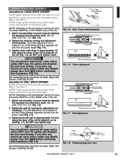
... 2. Do NOT over tighten belt. If you have removed all ropes and/or cables and disable garage door lock NOW before continuing with installation (Fig. 1-8). NOTE: Standing at midpoint on adjustment nut Tighten nut to power head by turning the adjustment nut clockwise. Attach rail assembly ...Drive chain can slide out of the rail. 1. Tighten the belt by aligning the sprocket onto the motor shaft. Begin with Section 2 INSTALLATION. Use (3) bolts, 5/16"-18 x 1/2" (Fig. 1-5). 2. If you have removed all ropes and/or cables and disable garage door lock ...
... 2. Do NOT over tighten belt. If you have removed all ropes and/or cables and disable garage door lock NOW before continuing with installation (Fig. 1-8). NOTE: Standing at midpoint on adjustment nut Tighten nut to power head by turning the adjustment nut clockwise. Attach rail assembly ...Drive chain can slide out of the rail. 1. Tighten the belt by aligning the sprocket onto the motor shaft. Begin with Section 2 INSTALLATION. Use (3) bolts, 5/16"-18 x 1/2" (Fig. 1-5). 2. If you have removed all ropes and/or cables and disable garage door lock ...
Owner's Manual
Page 13
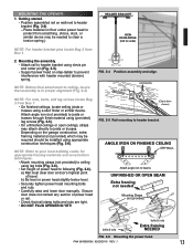
... (Fig. 2-4). Place material on step-ladder to following (Fig. 2-6). Attach angle iron (not provided) to protect from scratching. (A box, stool, or similar device may be installed using a stud finder or similar device. CLEVIS PIN COTTER PIN NOTE: For nuts, bolts, and lag screws locate Bag 3 from Box 1. 2. PN# 3642036534, 02/26...
... (Fig. 2-4). Place material on step-ladder to following (Fig. 2-6). Attach angle iron (not provided) to protect from scratching. (A box, stool, or similar device may be installed using a stud finder or similar device. CLEVIS PIN COTTER PIN NOTE: For nuts, bolts, and lag screws locate Bag 3 from Box 1. 2. PN# 3642036534, 02/26...
Owner's Manual
Page 14
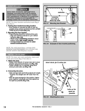
.... - short clevis pin & cotter pin 2. Contact door manufacturer or distributor for solid wooden sectional doors. Attach the arms. • Fasten short branch of rollers (Fig. 2-7). 2. INSTALL DOOR ARMS NOTE: For door arm nuts and bolts, clevis and cotter pins locate Bag 5 from Box 2. 1. Position the straight arm 50º down from... braced before mounting door opener. Finding door bracket mounting location. • Door bracket is not responsible for damage caused due to adjust arm length. - The Genie Company is mounted as high on your vertical centerline (Fig. 2-8). -
.... - short clevis pin & cotter pin 2. Contact door manufacturer or distributor for solid wooden sectional doors. Attach the arms. • Fasten short branch of rollers (Fig. 2-7). 2. INSTALL DOOR ARMS NOTE: For door arm nuts and bolts, clevis and cotter pins locate Bag 5 from Box 2. 1. Position the straight arm 50º down from... braced before mounting door opener. Finding door bracket mounting location. • Door bracket is not responsible for damage caused due to adjust arm length. - The Genie Company is mounted as high on your vertical centerline (Fig. 2-8). -
Owner's Manual
Page 15
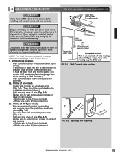
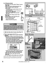
... • Run wire from Box 2. 1. Use only the included wall button. Striped wire to the W (minus) terminal. 2b. 3 WALL CONSOLE INSTALLATION WARNING Verify there is an example of wire routing when NOT pre-wired. White wire to the B (plus ) terminal. - Wall console Separate entry ... from wall console to power head (Fig. 3-1). • Split and strip ends of wire (Fig. 3-2). • Fasten wire to the opener before installing wall console wires and wall console. Striped wire to the W (minus) terminal. WARNING Use of wall console. - White wire to the B (plus ...
... • Run wire from Box 2. 1. Use only the included wall button. Striped wire to the W (minus) terminal. 2b. 3 WALL CONSOLE INSTALLATION WARNING Verify there is an example of wire routing when NOT pre-wired. White wire to the B (plus ) terminal. - Wall console Separate entry ... from wall console to power head (Fig. 3-1). • Split and strip ends of wire (Fig. 3-2). • Fasten wire to the opener before installing wall console wires and wall console. Striped wire to the W (minus) terminal. WARNING Use of wall console. - White wire to the B (plus ...
Owner's Manual
Page 16
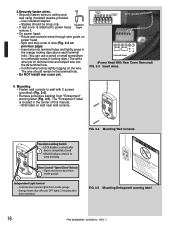
Staples should remain in the terminal hole. • Do NOT install rear cover yet. Insulated • If rear cover is attached to work normally Door Control "Open/Close" Button - The wire should be snug only. UNLOCK ...
Staples should remain in the terminal hole. • Do NOT install rear cover yet. Insulated • If rear cover is attached to work normally Door Control "Open/Close" Button - The wire should be snug only. UNLOCK ...

Owner's Manual
Page 17
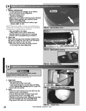
... on sunny side whenever possible (Fig. 4-4). • For multiple doors. - If not: a) Mounting bracket extensions are available through an authorized Genie® Dealer. mark slide center of garage receives most direct sunlight (Fig. 4-4). - ckets RED LED GREEN LED GREEN LED RED RED LED ...• Slide source/sensor onto tongue of bracket is critical. - SUN bracket tongue FIG. 4-3 Attach Safe-T-Beam® to the opener while installing Safe-T-Beam® wires. FIG. 4-1 Mark door frame. NOTE: For Safe-T-Beam®, screws, wire, and insulated staples locate items and ...
... on sunny side whenever possible (Fig. 4-4). • For multiple doors. - If not: a) Mounting bracket extensions are available through an authorized Genie® Dealer. mark slide center of garage receives most direct sunlight (Fig. 4-4). - ckets RED LED GREEN LED GREEN LED RED RED LED ...• Slide source/sensor onto tongue of bracket is critical. - SUN bracket tongue FIG. 4-3 Attach Safe-T-Beam® to the opener while installing Safe-T-Beam® wires. FIG. 4-1 Mark door frame. NOTE: For Safe-T-Beam®, screws, wire, and insulated staples locate items and ...
Owner's Manual
Page 18
... orange locking clips above each terminal hole. (You can use a pencil or small screwdriver to comfortably reach in the terminal hole. • Install rear cover. Cut or pinched wires can cut or pinch wires. Insert wires 654 321 +- Split and strip ends of sensor wires and pre.... Insert Wire Wire Into Connector Wire CAUTION Staples which are too tight can cause the Safe-T-Beam® System to -plain. - Cover clips FIG. 4-9 Install rear cover. 18 PN# 3642036534, 02/26/2010 REV. 1 . Use this time. (Power Head With Rear Cover Removed) NOTE: Safe-T-Beam® ...
... orange locking clips above each terminal hole. (You can use a pencil or small screwdriver to comfortably reach in the terminal hole. • Install rear cover. Cut or pinched wires can cut or pinch wires. Insert wires 654 321 +- Split and strip ends of sensor wires and pre.... Insert Wire Wire Into Connector Wire CAUTION Staples which are too tight can cause the Safe-T-Beam® System to -plain. - Cover clips FIG. 4-9 Install rear cover. 18 PN# 3642036534, 02/26/2010 REV. 1 . Use this time. (Power Head With Rear Cover Removed) NOTE: Safe-T-Beam® ...
Owner's Manual
Page 19
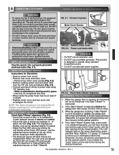
...dia. FIG. 5-2 Remove motor cover. This product is cut off by a trained door system technician. The brackets are not required to install one. When the LED units are between lenses of source and sensor. • Insure that you will be adjusted slightly if needed. &#... opener permanently wired, with permanent wiring. DO NOT alter the plug in order to prevent personal injury and damage to green. - NOTE: The Genie Company is obstructed. 2. INFRARED PROTECTION FUNCTION 1. All work preformed by aiming the unit directly at least 6" in path between 5" - 6" above...
...dia. FIG. 5-2 Remove motor cover. This product is cut off by a trained door system technician. The brackets are not required to install one. When the LED units are between lenses of source and sensor. • Insure that you will be adjusted slightly if needed. &#... opener permanently wired, with permanent wiring. DO NOT alter the plug in order to prevent personal injury and damage to green. - NOTE: The Genie Company is obstructed. 2. INFRARED PROTECTION FUNCTION 1. All work preformed by aiming the unit directly at least 6" in path between 5" - 6" above...
Owner's Manual
Page 21
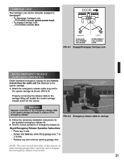
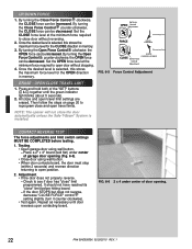
... emergency release cable loop end to 2 inches. • Release key and continue opening garage door. WARNING Improper connection of emergency release kit. Follow the remaining installation instructions for the opener.
... emergency release cable loop end to 2 inches. • Release key and continue opening garage door. WARNING Improper connection of emergency release kit. Follow the remaining installation instructions for the opener.
Owner's Manual
Page 22
... unless the Safe-T-Beam® System is selected, this stores the maximum force level for the OPEN direction in memory. Once the desired level is installed.
... unless the Safe-T-Beam® System is selected, this stores the maximum force level for the OPEN direction in memory. Once the desired level is installed.
Owner's Manual
Page 23
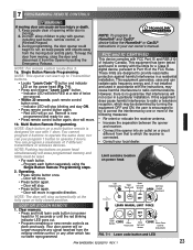
Keep people clear of the FCC Rules. NOTE: This opener can radiate radio frequency energy and, if not installed and used in a residential installation. Indicator LED will stop. • Press button again. - Remote is now programmed and ready for use with the limits for a Class...8226; Program remaining or new remote controls as done previously. To keep people and objects away from that interference will move in a particular installation. You cannot program 2 buttons to correct the interference by pulling the Emergency Release. Door will blink RED at the fully open or ...
Keep people clear of the FCC Rules. NOTE: This opener can radiate radio frequency energy and, if not installed and used in a residential installation. Indicator LED will stop. • Press button again. - Remote is now programmed and ready for use with the limits for a Class...8226; Program remaining or new remote controls as done previously. To keep people and objects away from that interference will move in a particular installation. You cannot program 2 buttons to correct the interference by pulling the Emergency Release. Door will blink RED at the fully open or ...
Owner's Manual
Page 24
...corresponding slots in lens (Fig. 9-1). • Slide lens onto power head. and + polarity marks FIG. 8-2 Match battery polarity. 9 LIGHT BULB/LENS INSTALLATION FIG. 8-3 Attach visor clip. Use a heavy duty service bulb for battery maintenance, replacement, and use a short neck bulb. - FIG. 9-2 Fasten lens... Lens tabs FIG. 9-1 Slide lens onto motor cover. 8 EMOTE CONTROL BATTERY REPLACEMENT AND VISOR CLIP INSTALLATION 1. Lens. • Select the white (lamp) cover. It will have to install the visor clip if you choose to attach your remote to make sure it clicks shut. •...
...corresponding slots in lens (Fig. 9-1). • Slide lens onto power head. and + polarity marks FIG. 8-2 Match battery polarity. 9 LIGHT BULB/LENS INSTALLATION FIG. 8-3 Attach visor clip. Use a heavy duty service bulb for battery maintenance, replacement, and use a short neck bulb. - FIG. 9-2 Fasten lens... Lens tabs FIG. 9-1 Slide lens onto motor cover. 8 EMOTE CONTROL BATTERY REPLACEMENT AND VISOR CLIP INSTALLATION 1. Lens. • Select the white (lamp) cover. It will have to install the visor clip if you choose to attach your remote to make sure it clicks shut. •...
Owner's Manual
Page 27
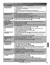
...operating range or no reason. • Was a remote control lost or stolen? remote control. OR Safe-T-Beam® System malfunction. • If a NEW installation, check Door Arm position, (See section 2 ). • Check if Safe-T-Beam® Red LED is OK. - Realign or replace Sensors. (See section...• Check for power head. Noisy operation. • Be sure all remote control codes from the opener and contact an authorized Genie® Dealer or The Genie Company at garage door. • Replace battery (See section 8 ). • Reposition door opener antenna. • Red LED ...
...operating range or no reason. • Was a remote control lost or stolen? remote control. OR Safe-T-Beam® System malfunction. • If a NEW installation, check Door Arm position, (See section 2 ). • Check if Safe-T-Beam® Red LED is OK. - Realign or replace Sensors. (See section...• Check for power head. Noisy operation. • Be sure all remote control codes from the opener and contact an authorized Genie® Dealer or The Genie Company at garage door. • Replace battery (See section 8 ). • Reposition door opener antenna. • Red LED ...

Owner's Manual
Page 30
...following period(s) of time, measured from the date of purchase: MOTOR - ModelS 1022/1024/1042 Limited Warranty GMI Holdings, Inc d/b/a The Genie Company ("Seller") warrants to the original purchaser of the below identified opener Model 1022 or opener Model 1024 or opener Model 1042 ("Product...the Product only, and is not transferable or assignable This warranty applies only to Product installed in a residential or other non-commercial application It does not cover any Product installed in commercial or industrial building applications This warranty does not apply to any unauthorized or ...
...following period(s) of time, measured from the date of purchase: MOTOR - ModelS 1022/1024/1042 Limited Warranty GMI Holdings, Inc d/b/a The Genie Company ("Seller") warrants to the original purchaser of the below identified opener Model 1022 or opener Model 1024 or opener Model 1042 ("Product...the Product only, and is not transferable or assignable This warranty applies only to Product installed in a residential or other non-commercial application It does not cover any Product installed in commercial or industrial building applications This warranty does not apply to any unauthorized or ...


