
PU-DLS User Manual
Page 15
.... ASUS PU-DLS motherboard Extended ATX form factor: 12 in x 13 in (30.5 cm x 33 cm) ASUS PU-DLS support CD I/O shield 80-conductor ribbon cable for UltraDMA100/66/33 IDE drives Ribbon cable for buying the ASUS® PU-DLS motherboard! ASUS PU-DLS motherboard user guide 1-1 Before you for a 3.5-inch floppy drive Bag of extra jumper caps PU-DLS User Guide If any of ASUS quality server motherboards! The ASUS PU-DLS motherboard delivers...
.... ASUS PU-DLS motherboard Extended ATX form factor: 12 in x 13 in (30.5 cm x 33 cm) ASUS PU-DLS support CD I/O shield 80-conductor ribbon cable for UltraDMA100/66/33 IDE drives Ribbon cable for buying the ASUS® PU-DLS motherboard! ASUS PU-DLS motherboard user guide 1-1 Before you for a 3.5-inch floppy drive Bag of extra jumper caps PU-DLS User Guide If any of ASUS quality server motherboards! The ASUS PU-DLS motherboard delivers...
PU-DLS User Manual
Page 16
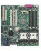
DDR memory support Employing the Double Data Rate (DDR) memory technology, the PU-DLS motherboard supports up to 12GB of system memory using PC2100/1600 registered ECC DDR DIMMs. The ultra-fast 266/200MHz memory bus doubles ... PCI-X bus onboard maximizes I /O and server management cards. Dual-channel Ultra-320 SCSI The Adaptec 7902W Ultra-320 SCSI controller and dual-channel SCSI connectors are onboard to offer a significant increase in performance. 1.3 Special features 1.3.1 Product highlights Latest processor technology The PU-DLS motherboard supports the Intel® Xeon processor via ...
DDR memory support Employing the Double Data Rate (DDR) memory technology, the PU-DLS motherboard supports up to 12GB of system memory using PC2100/1600 registered ECC DDR DIMMs. The ultra-fast 266/200MHz memory bus doubles ... PCI-X bus onboard maximizes I /O and server management cards. Dual-channel Ultra-320 SCSI The Adaptec 7902W Ultra-320 SCSI controller and dual-channel SCSI connectors are onboard to offer a significant increase in performance. 1.3 Special features 1.3.1 Product highlights Latest processor technology The PU-DLS motherboard supports the Intel® Xeon processor via ...

PU-DLS User Manual
Page 39
... 133MHz data transfers, or about 1.06GB/s. PCI1/PCI2 slots PCI1 and PCI2 are 32-bit/33MHz 5V PCI slots. The PCI bus speed for servers to install PCI and PCI-X cards at the same time, but the bus speed will be that of expansion cards installed on the slots. (... SCSI. ASUS PU-DLS motherboard user guide 2-13 PCI-X4 PCI-X3 PCI-X2 PCI-X1 PCI2 PCI1 PCI-X slots (PCI X1 to 33MHz. PCI-X is fixed to X4) The PCI-X bus speeds vary depending on the number of the slowest card. 2.6.3 PCI slots This motherboard implements the PCI-X (Peripheral Component Interconnect Extended) bus ...
... 133MHz data transfers, or about 1.06GB/s. PCI1/PCI2 slots PCI1 and PCI2 are 32-bit/33MHz 5V PCI slots. The PCI bus speed for servers to install PCI and PCI-X cards at the same time, but the bus speed will be that of expansion cards installed on the slots. (... SCSI. ASUS PU-DLS motherboard user guide 2-13 PCI-X4 PCI-X3 PCI-X2 PCI-X1 PCI2 PCI1 PCI-X slots (PCI X1 to 33MHz. PCI-X is fixed to X4) The PCI-X bus speeds vary depending on the number of the slowest card. 2.6.3 PCI slots This motherboard implements the PCI-X (Peripheral Component Interconnect Extended) bus ...

PU-DLS User Manual
Page 49
8. Server management card connector (50-pin CON1) This connector allows you to accommodate the ASMC card. ® PU-DLS PU-DLS eRMC Connector 9. Install the ASMC card into the PCI1 slot and connect the cable from the card to this connector. IPMI connector (4-...PCI1 slot on the motherboard has a Low Pin Count (LPC) signal connector to connect the optional ASMC-LE, ASMC-ME, or ASMC-HE card using an ASMC interface cable. Connect the 4-pin ASMC interface cable to this connector. CON2 PU-DLS IPMI Connector ® PU-DLS NC IPMICLK GND IPMIDATA ASUS PU-DLS motherboard user guide 2-23
8. Server management card connector (50-pin CON1) This connector allows you to accommodate the ASMC card. ® PU-DLS PU-DLS eRMC Connector 9. Install the ASMC card into the PCI1 slot and connect the cable from the card to this connector. IPMI connector (4-...PCI1 slot on the motherboard has a Low Pin Count (LPC) signal connector to connect the optional ASMC-LE, ASMC-ME, or ASMC-HE card using an ASMC interface cable. Connect the 4-pin ASMC interface cable to this connector. CON2 PU-DLS IPMI Connector ® PU-DLS NC IPMICLK GND IPMIDATA ASUS PU-DLS motherboard user guide 2-23
PU-DLS User Manual
Page 58
Chapter summary 4.1 Managing and updating your BIOS 4-1 4.2 BIOS Setup program 4-5 4.3 Main Menu 4-8 4.4 Advanced Menu 4-15 4.5 Power Menu 4-23 4.6 Boot Menu 4-28 4.7 Server Menu 4-30 4.8 Exit Menu 4-31 ASUS PU-DLS motherboard
Chapter summary 4.1 Managing and updating your BIOS 4-1 4.2 BIOS Setup program 4-5 4.3 Main Menu 4-8 4.4 Advanced Menu 4-15 4.5 Power Menu 4-23 4.6 Boot Menu 4-28 4.7 Server Menu 4-30 4.8 Exit Menu 4-31 ASUS PU-DLS motherboard

PU-DLS User Manual
Page 92
Chapter summary 5.1 Support CD contents 5-1 5.2 Microsoft Windows NT Server 4.0 5-3 5.3 Microsoft Windows 2000 Server 5-12 5.4 Microsoft Windows XP Professional .......... 5-22 5.5 Novell NetWare Server 5-31 5.6 SCO Open Server 5.0.6 5-39 5.7 Linux RedHat 8.0 5-41 ASUS PU-DLS motherboard
Chapter summary 5.1 Support CD contents 5-1 5.2 Microsoft Windows NT Server 4.0 5-3 5.3 Microsoft Windows 2000 Server 5-12 5.4 Microsoft Windows XP Professional .......... 5-22 5.5 Novell NetWare Server 5-31 5.6 SCO Open Server 5.0.6 5-39 5.7 Linux RedHat 8.0 5-41 ASUS PU-DLS motherboard
PU-DLS User Manual
Page 93
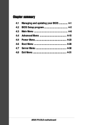
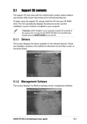
... the ASUS proprietary server management software. The CD automatically displays the welcome screen and the installation menus if Autorun is NOT enabled in each of the support CD to run the CD. 5.1.1 Drivers This screen displays the drivers available for the onboard devices. ASUS PU-DLS motherboard user ...guide 5-1 5.1 Support CD contents The support CD that came with the motherboard contains useful software and several utility drivers that enhance the...
... the ASUS proprietary server management software. The CD automatically displays the welcome screen and the installation menus if Autorun is NOT enabled in each of the support CD to run the CD. 5.1.1 Drivers This screen displays the drivers available for the onboard devices. ASUS PU-DLS motherboard user ...guide 5-1 5.1 Support CD contents The support CD that came with the motherboard contains useful software and several utility drivers that enhance the...
PU-DLS User Manual
Page 95
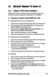
5.2 Microsoft® Windows® NT Server 4.0 5.2.1 Adaptec® SCSI driver installation Windows NT 4.0 does not have the driver for the SCSI controllers. You must load the driver manually prior to complete ... a blank formatted high-density floppy disk into the CD-ROM drive. Using the Drivers menu in the following folder path: \drivers\adaptec\7902\ ASUS PU-DLS motherboard user guide 5-3 The ASUS File Image Extractor window appears. 4. Follow the succeeding screen instructions to display the folders and sub-folders in the support CD. 4. Copy the entire...
5.2 Microsoft® Windows® NT Server 4.0 5.2.1 Adaptec® SCSI driver installation Windows NT 4.0 does not have the driver for the SCSI controllers. You must load the driver manually prior to complete ... a blank formatted high-density floppy disk into the CD-ROM drive. Using the Drivers menu in the following folder path: \drivers\adaptec\7902\ ASUS PU-DLS motherboard user guide 5-3 The ASUS File Image Extractor window appears. 4. Follow the succeeding screen instructions to display the folders and sub-folders in the support CD. 4. Copy the entire...

PU-DLS User Manual
Page 111
Highlight the Intel(R) PRO-1000 Server Adapter, click the right mouse button, and select Properties to display the following . ASUS PU-DLS motherboard user guide 5-19 Highlight the Intel(R) 82554GC-based Network Connection, click the right mouse button, and select Properties to display the following . 4. 3.
Highlight the Intel(R) PRO-1000 Server Adapter, click the right mouse button, and select Properties to display the following . ASUS PU-DLS motherboard user guide 5-19 Highlight the Intel(R) 82554GC-based Network Connection, click the right mouse button, and select Properties to display the following . 4. 3.

PU-DLS User Manual
Page 123
.... 7. Insert the Adaptec Ultra320 FMS Driver disk for Novell Netware. 4. ASUS PU-DLS motherboard user guide 5-31 The Drivers menu appears displaying the available drivers. 3. Begin installation of NetWare on your server as instructed in your NetWare documentation. 2. Preparing an Adaptec Ultra320 FMS driver... screen instructtions to create an Adaptec Ultra320 FMS driver disk for NetWare into the CD-ROM drive. 5.5 Novell® NetWare® Server 5.5.1 Adaptec® SCSI Driver Installation A. Select "Return to driver list" to accept the default slot number, and press ENTER. ...
.... 7. Insert the Adaptec Ultra320 FMS Driver disk for Novell Netware. 4. ASUS PU-DLS motherboard user guide 5-31 The Drivers menu appears displaying the available drivers. 3. Begin installation of NetWare on your server as instructed in your NetWare documentation. 2. Preparing an Adaptec Ultra320 FMS driver... screen instructtions to create an Adaptec Ultra320 FMS driver disk for NetWare into the CD-ROM drive. 5.5 Novell® NetWare® Server 5.5.1 Adaptec® SCSI Driver Installation A. Select "Return to driver list" to accept the default slot number, and press ENTER. ...

PU-DLS User Manual
Page 127
... the line(s) for loading ADPU320.HAM driver. 5. Press ESC twice to save and exit. 6. 13. Select "NCF Files Option (Create/Edit server Startup files)". 3. When finished, press F10 to quit NWCONFIG utility. NOTE A DOS text editor can also be used to select the slot number... screen. Removing the Driver From a NetWare Server 1. Select "Edit STARTUP.NCF file". 4. When prompted, press ENTER to modify the STARTUP.NCF file. Click "No" at the NetWare console prompt and press ENTER. 2. Press Esc until all slot options are loaded. 14. F. ASUS PU-DLS motherboard user guide 5-35
... the line(s) for loading ADPU320.HAM driver. 5. Press ESC twice to save and exit. 6. 13. Select "NCF Files Option (Create/Edit server Startup files)". 3. When finished, press F10 to quit NWCONFIG utility. NOTE A DOS text editor can also be used to select the slot number... screen. Removing the Driver From a NetWare Server 1. Select "Edit STARTUP.NCF file". 4. When prompted, press ENTER to modify the STARTUP.NCF file. Click "No" at the NetWare console prompt and press ENTER. 2. Press Esc until all slot options are loaded. 14. F. ASUS PU-DLS motherboard user guide 5-35
PU-DLS User Manual
Page 131
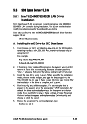
.... For each adapter that is complete, exit 'custom'. 4. Reboot the system.At the command prompt, type: # reboot (or init 6) ASUS PU-DLS motherboard user guide 5-39 If there is an older version of the driver is present in the system, enter the appropriate TCP/IP parameters. Remove...adapters. Exit netconfig without opting to relink the kernel. 5. If you must first remove it to /tmp, type '/tmp'). 5.6 SCO Open Server 5.0.6 5.6.1 Intel® 82544GC/82540EM LAN Driver Installation SCO OpenServer 5.0.6 system can find the Intel 82544GC/82540EM Network driver from the support CD at...
.... For each adapter that is complete, exit 'custom'. 4. Reboot the system.At the command prompt, type: # reboot (or init 6) ASUS PU-DLS motherboard user guide 5-39 If there is an older version of the driver is present in the system, enter the appropriate TCP/IP parameters. Remove...adapters. Exit netconfig without opting to relink the kernel. 5. If you must first remove it to /tmp, type '/tmp'). 5.6 SCO Open Server 5.0.6 5.6.1 Intel® 82544GC/82540EM LAN Driver Installation SCO OpenServer 5.0.6 system can find the Intel 82544GC/82540EM Network driver from the support CD at...


