PU-DLS User Manual
Page 3
... in this guide ix Where to find more information ix ASUS contact information x PU-DLS specifications summary xi Chapter 1: Product introduction 1.1 Welcome 1-1 1.2 Package contents 1-1 1.3 Special features 1-2 1.3.1 Product highlights 1-2 1.3.2 Value-added solutions 1-4 1.4 Motherboard overview 1-6 1.4.1 Major components 1-6 1.4.2 Core specifications 1-8 Chapter 2: Hardware information 2.1 Motherboard installation 2-1 2.1.1 Placement direction 2-1 2.1.2 Screw holes 2-1 2.2 Motherboard layout 2-2 2.3 Before you proceed 2-3 2.4 Central Processing Unit (CPU 2-4 2.4.1 Overview...
... in this guide ix Where to find more information ix ASUS contact information x PU-DLS specifications summary xi Chapter 1: Product introduction 1.1 Welcome 1-1 1.2 Package contents 1-1 1.3 Special features 1-2 1.3.1 Product highlights 1-2 1.3.2 Value-added solutions 1-4 1.4 Motherboard overview 1-6 1.4.1 Major components 1-6 1.4.2 Core specifications 1-8 Chapter 2: Hardware information 2.1 Motherboard installation 2-1 2.1.1 Placement direction 2-1 2.1.2 Screw holes 2-1 2.2 Motherboard layout 2-2 2.3 Before you proceed 2-3 2.4 Central Processing Unit (CPU 2-4 2.4.1 Overview...
PU-DLS User Manual
Page 11
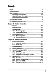
PU-DLS specifications summary CPU Chipsets Front Side Bus (FSB) Memory Onboard LAN Onboard SCSI Expansion slots Rear panel I/O Internal connectors ...MHz 6 x 184-pin DDR DIMM sockets Supports PC2100/PC1600 registered ECC DDR DIMMs Supports up to 12GB system memory using 2GB DIMMs Intel® 82540EM 32-bit PCI Gigabit Ethernet controller Intel® 82544GC 64-bit PCI-X Gigabit... 4Mb Firmware Hub (FWH), Award BIOS with ACPI, DMI, Green, PnP features, and Enhanced Server BIOS features Extended ATX form factor: 12 in x 13 in (30.5 cm x 33 cm) Device drivers Utilities Contact information * Specifications are...
PU-DLS specifications summary CPU Chipsets Front Side Bus (FSB) Memory Onboard LAN Onboard SCSI Expansion slots Rear panel I/O Internal connectors ...MHz 6 x 184-pin DDR DIMM sockets Supports PC2100/PC1600 registered ECC DDR DIMMs Supports up to 12GB system memory using 2GB DIMMs Intel® 82540EM 32-bit PCI Gigabit Ethernet controller Intel® 82544GC 64-bit PCI-X Gigabit... 4Mb Firmware Hub (FWH), Award BIOS with ACPI, DMI, Green, PnP features, and Enhanced Server BIOS features Extended ATX form factor: 12 in x 13 in (30.5 cm x 33 cm) Device drivers Utilities Contact information * Specifications are...
PU-DLS User Manual
Page 16
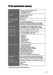
...-Channel RAID feature and multi-level RAID 0, 1, 5. 1-2 Chapter 1: Product introduction DDR memory support Employing the Double Data Rate (DDR) memory technology, the PU-DLS motherboard supports up to 12GB of system memory using PC2100/1600 registered ECC DDR DIMMs. The ultra-fast 266/200MHz memory bus doubles the speed of the PC133/PC100 SDRAM to deliver the...
...-Channel RAID feature and multi-level RAID 0, 1, 5. 1-2 Chapter 1: Product introduction DDR memory support Employing the Double Data Rate (DDR) memory technology, the PU-DLS motherboard supports up to 12GB of system memory using PC2100/1600 registered ECC DDR DIMMs. The ultra-fast 266/200MHz memory bus doubles the speed of the PC133/PC100 SDRAM to deliver the...

PU-DLS User Manual
Page 18
... the BIOS setting. The system voltage levels are monitored to the motherboard. ACPI ready The Advanced Configuration power Interface (ACPI) provides more than 4 seconds puts the system to sleep mode or to the memory and processor. Smart BIOS The 4Mbit firmware hub (FWH) gives an...Year 2000 certified. 1-4 Chapter 1: Product introduction Dual function power switch While the system is monitored by the ASUS ASIC to prevent overheating and damage. Wake-Up support The motherboard includes Wake-On-LAN, Wake-On-Ring, and BIOS Wake-Up features. 1.3.2 Value-added solutions Temperature, ...
... the BIOS setting. The system voltage levels are monitored to the motherboard. ACPI ready The Advanced Configuration power Interface (ACPI) provides more than 4 seconds puts the system to sleep mode or to the memory and processor. Smart BIOS The 4Mbit firmware hub (FWH) gives an...Year 2000 certified. 1-4 Chapter 1: Product introduction Dual function power switch While the system is monitored by the ASUS ASIC to prevent overheating and damage. Wake-Up support The motherboard includes Wake-On-LAN, Wake-On-Ring, and BIOS Wake-Up features. 1.3.2 Value-added solutions Temperature, ...
PU-DLS User Manual
Page 22
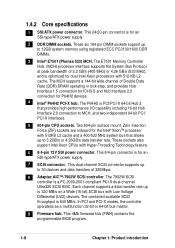
... firmware hub (FWH) contains the programmable BIOS program. 1-8 Chapter 1: Product introduction This 24/20-pin connector is 640 MB/s. The E7501 Memory Controller Hub (MCH) processor interface supports the System Bus Protocol at peak bandwidth of 320Mbps. 8 Adaptec AIC™-7902W SCSI controller. The P64H2... Interface 2.0 connection for the Intel® Xeon™ processor with 512-KB L2 cache. The 7902W SCSI controller is for an SSI-type/ATX power supply. 2 DDR DIMM sockets. These six 184-pin DIMM sockets support up to 3.2GB/s or 4.26GB/s data transfer rate. Each channel...
... firmware hub (FWH) contains the programmable BIOS program. 1-8 Chapter 1: Product introduction This 24/20-pin connector is 640 MB/s. The E7501 Memory Controller Hub (MCH) processor interface supports the System Bus Protocol at peak bandwidth of 320Mbps. 8 Adaptec AIC™-7902W SCSI controller. The P64H2... Interface 2.0 connection for the Intel® Xeon™ processor with 512-KB L2 cache. The 7902W SCSI controller is for an SSI-type/ATX power supply. 2 DDR DIMM sockets. These six 184-pin DIMM sockets support up to 3.2GB/s or 4.26GB/s data transfer rate. Each channel...
PU-DLS User Manual
Page 26
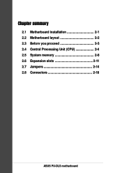
Chapter summary 2.1 Motherboard installation 2-1 2.2 Motherboard layout 2-2 2.3 Before you proceed 2-3 2.4 Central Processing Unit (CPU 2-4 2.5 System memory 2-8 2.6 Expansion slots 2-11 2.7 Jumpers 2-14 2.8 Connectors 2-18 ASUS PU-DLS motherboard
Chapter summary 2.1 Motherboard installation 2-1 2.2 Motherboard layout 2-2 2.3 Before you proceed 2-3 2.4 Central Processing Unit (CPU 2-4 2.5 System memory 2-8 2.6 Expansion slots 2-11 2.7 Jumpers 2-14 2.8 Connectors 2-18 ASUS PU-DLS motherboard

PU-DLS User Manual
Page 34
These sockets support up to 12GB system memory using 184-pin registered PC2100/1600 DIMMs with Serial Presence Detect (SPD) and Error Check and Correction (ECC). ® PU-DLS PU-DLS 184-Pin DDR DIMM Sockets 104 Pins 80 Pins DDR6 DDR5 DDR4 DDR3 DDR2 DDR1 A DDR DIMM is keyed ... DDR SDRAM technology evolved from the mainstream PC66, PC100, PC133 memory known as an SDR DIMM, but it fits in one direction. DDR memory however, has the ability to avoid damaging the DIMM. 2.5 System memory 2.5.1 Overview The motherboard comes with SDR, and should be installed only in a socket ...
These sockets support up to 12GB system memory using 184-pin registered PC2100/1600 DIMMs with Serial Presence Detect (SPD) and Error Check and Correction (ECC). ® PU-DLS PU-DLS 184-Pin DDR DIMM Sockets 104 Pins 80 Pins DDR6 DDR5 DDR4 DDR3 DDR2 DDR1 A DDR DIMM is keyed ... DDR SDRAM technology evolved from the mainstream PC66, PC100, PC133 memory known as an SDR DIMM, but it fits in one direction. DDR memory however, has the ability to avoid damaging the DIMM. 2.5 System memory 2.5.1 Overview The motherboard comes with SDR, and should be installed only in a socket ...
PU-DLS User Manual
Page 35
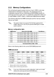
.../1600 registered ECC DIMMs. Make sure to use a 128-bit memory width configuration, make sure to install identical (the same type and size) DDR DIMM pairs. ASUS PU-DLS motherboard user guide 2-9 2.5.2 Memory Configurations The motherboard supports system memory of up to 12GB in pairs. The interleaved memory configuration requires that you install identical DDR DIMMs (exactly the same...
.../1600 registered ECC DIMMs. Make sure to use a 128-bit memory width configuration, make sure to install identical (the same type and size) DDR DIMM pairs. ASUS PU-DLS motherboard user guide 2-9 2.5.2 Memory Configurations The motherboard supports system memory of up to 12GB in pairs. The interleaved memory configuration requires that you install identical DDR DIMMs (exactly the same...
PU-DLS User Manual
Page 43
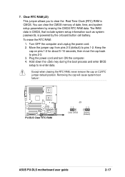
You can clear the CMOS memory of date, time, and system setup parameters by the onboard button cell battery. The RAM data in CMOS. Move the jumper cap from pins 2-3 (default) ... such as system passwords, is powered by erasing the CMOS RTC RAM data. Removing the cap will cause system boot failure! ® PU-DLS PU-DLS Clear RTC RAM J3 12 23 Clear CMOS Normal (Default) ASUS PU-DLS motherboard user guide 2-17 To erase the RTC RAM: 1. Clear RTC RAM (J3) This jumper allows you to pins 2-3. 3.
You can clear the CMOS memory of date, time, and system setup parameters by the onboard button cell battery. The RAM data in CMOS. Move the jumper cap from pins 2-3 (default) ... such as system passwords, is powered by erasing the CMOS RTC RAM data. Removing the cap will cause system boot failure! ® PU-DLS PU-DLS Clear RTC RAM J3 12 23 Clear CMOS Normal (Default) ASUS PU-DLS motherboard user guide 2-17 To erase the RTC RAM: 1. Clear RTC RAM (J3) This jumper allows you to pins 2-3. 3.
PU-DLS User Manual
Page 50
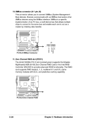
... one to connect SMBus (System Management Bus) devices. The RAID card supports RAID levels 0, 1, 5, multilevel 0/1 and 0/5, cache memory modules with an SMBus host and/or other SMBus devices using the SMBus interface. ® PU-DLS 10. Zero Channel RAID slot (PCIX1) The 64-bit/100MHz PCI-X slot (colored green) supports the Adaptec Nighthawk2...
... one to connect SMBus (System Management Bus) devices. The RAID card supports RAID levels 0, 1, 5, multilevel 0/1 and 0/5, cache memory modules with an SMBus host and/or other SMBus devices using the SMBus interface. ® PU-DLS 10. Zero Channel RAID slot (PCIX1) The 64-bit/100MHz PCI-X slot (colored green) supports the Adaptec Nighthawk2...

PU-DLS User Manual
Page 55
...working Meaning No error during POST No DRAM installed or detected Video card not found or video card memory bad CPU overheated; System power (if you are using an ATX power supply, you need to enter BIOS Setup. After making all switches are running at the back...ATX power switch. Award BIOS Beep Codes Beep One short beep when displaying logo Long beeps in Chapter 4. After applying power, the power LED on tests. The system then runs the power-on the system front panel case lights up. Connect the power cord to the power connector at a lower frequency 7. ASUS PU-DLS motherboard...
...working Meaning No error during POST No DRAM installed or detected Video card not found or video card memory bad CPU overheated; System power (if you are using an ATX power supply, you need to enter BIOS Setup. After making all switches are running at the back...ATX power switch. Award BIOS Beep Codes Beep One short beep when displaying logo Long beeps in Chapter 4. After applying power, the power LED on tests. The system then runs the power-on the system front panel case lights up. Connect the power cord to the power connector at a lower frequency 7. ASUS PU-DLS motherboard...
PU-DLS User Manual
Page 59
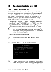
...prompt to run AFLASH. If the word "unknown" appears after Flash Memory:, the memory chip is either not programmable or is a Flash Memory Writer utility that you created. To determine the BIOS version of your motherboard, check the last four numbers of the code displayed on the ...loaded when you boot from the floppy disk. It does not work with certain memory drivers that may be programmed by uploading a new BIOS file to the programmable firmware hub (FWH) on the motherboard. ASUS PU-DLS motherboard user guide 4-1 In DOS mode, type A:\AFLASH to create a bootable system disk...
...prompt to run AFLASH. If the word "unknown" appears after Flash Memory:, the memory chip is either not programmable or is a Flash Memory Writer utility that you created. To determine the BIOS version of your motherboard, check the last four numbers of the code displayed on the ...loaded when you boot from the floppy disk. It does not work with certain memory drivers that may be programmed by uploading a new BIOS file to the programmable firmware hub (FWH) on the motherboard. ASUS PU-DLS motherboard user guide 4-1 In DOS mode, type A:\AFLASH to create a bootable system disk...
PU-DLS User Manual
Page 62
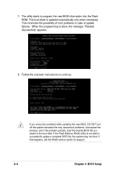
... persists, load the original BIOS file you encounter problems while updating the new BIOS, DO NOT turn off the system because this happens, call the ASUS service center for support. 4-4 Chapter 4: BIOS Setup The utility starts to continue. This minimizes the possibility of boot problems in case of update failures. If...
... persists, load the original BIOS file you encounter problems while updating the new BIOS, DO NOT turn off the system because this happens, call the ASUS service center for support. 4-4 Chapter 4: BIOS Setup The utility starts to continue. This minimizes the possibility of boot problems in case of update failures. If...
PU-DLS User Manual
Page 67
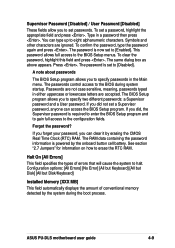
ASUS PU-DLS motherboard user guide 4-9 To set to [Enabled]. Press . Forgot the password? See section ... password, highlight the appropriate field and press . Halt On [All Errors] This field specifies the types of conventional memory detected by the onboard button cell battery. If you forget your password, you did not set a Supervisor password,...options: [All Errors] [No Error] [All but Keyboard] [All but Disk] [All but Disk/Keyboard] Installed Memory [XXX MB] This field automatically displays the amount of errors that will cause the system to the BIOS Setup menus....
ASUS PU-DLS motherboard user guide 4-9 To set to [Enabled]. Press . Forgot the password? See section ... password, highlight the appropriate field and press . Halt On [All Errors] This field specifies the types of conventional memory detected by the onboard button cell battery. If you forget your password, you did not set a Supervisor password,...options: [All Errors] [No Error] [All but Keyboard] [All but Disk] [All but Disk/Keyboard] Installed Memory [XXX MB] This field automatically displays the amount of errors that will cause the system to the BIOS Setup menus....
PU-DLS User Manual
Page 74
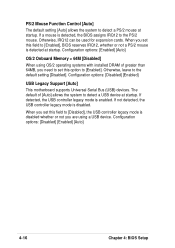
... mode is disabled. Configuration options: [Disabled] [Enabled] [Auto] 4-16 Chapter 4: BIOS Setup Configuration options: [Enabled] [Auto] OS/2 Onboard Memory > 64M [Disabled] When using a USB device. When you set this field to detect a USB device at startup. Configuration options: [Disabled] ...[Enabled] USB Legacy Support [Auto] This motherboard supports Universal Serial Bus (USB) devices. When you set this option to the default setting [Disabled]. If a mouse is detected, ...
... mode is disabled. Configuration options: [Disabled] [Enabled] [Auto] 4-16 Chapter 4: BIOS Setup Configuration options: [Enabled] [Auto] OS/2 Onboard Memory > 64M [Disabled] When using a USB device. When you set this field to detect a USB device at startup. Configuration options: [Disabled] ...[Enabled] USB Legacy Support [Auto] This motherboard supports Universal Serial Bus (USB) devices. When you set this option to the default setting [Disabled]. If a mouse is detected, ...

PU-DLS User Manual
Page 75
ASUS PU-DLS motherboard user guide 4-17 SDRAM CAS Latency [2.5T] This item controls the...which configures items 2-5 by reading the contents in the SPD (Serial Presence Detect) device. The EEPROM on the memory modules that you set the SDRAM Configuration to [User Defined]. The default setting is recommended to keep the default setting... SPD] This parameter allows you to set the optimal timings for items 2-5, depending on the memory module stores critical information about the module, such as memory type, size, speed, voltage interface, and module banks. It is recommended to CAS Delay...
ASUS PU-DLS motherboard user guide 4-17 SDRAM CAS Latency [2.5T] This item controls the...which configures items 2-5 by reading the contents in the SPD (Serial Presence Detect) device. The EEPROM on the memory modules that you set the SDRAM Configuration to [User Defined]. The default setting is recommended to keep the default setting... SPD] This parameter allows you to set the optimal timings for items 2-5, depending on the memory module stores critical information about the module, such as memory type, size, speed, voltage interface, and module banks. It is recommended to CAS Delay...

PU-DLS User Manual
Page 76
...improve the display speed by caching the display data. Setting the address space to a particular setting makes that memory space unavailable to the DDR SDRAM. Video Memory Cache Mode [UC] USWC (uncacheable, speculative write combining) is recommended to [Enabled], this feature, otherwise the...This item controls the idle clocks after issuing a precharge command to other system components. It is a new cache technology for the video memory of DDR SDRAM clocks used for stable system operation. It is accessing 8-bit LPC, FWH, and ICH3 internal registers. Configuration options: ...
...improve the display speed by caching the display data. Setting the address space to a particular setting makes that memory space unavailable to the DDR SDRAM. Video Memory Cache Mode [UC] USWC (uncacheable, speculative write combining) is recommended to [Enabled], this feature, otherwise the...This item controls the idle clocks after issuing a precharge command to other system components. It is a new cache technology for the video memory of DDR SDRAM clocks used for stable system operation. It is accessing 8-bit LPC, FWH, and ICH3 internal registers. Configuration options: ...


