
PU-DLS User Manual
Page 1
Motherboard PU-DLS User Guide
Motherboard PU-DLS User Guide
PU-DLS User Manual
Page 3
... in this guide ix Where to find more information ix ASUS contact information x PU-DLS specifications summary xi Chapter 1: Product introduction 1.1 Welcome 1-1 1.2 Package contents 1-1 1.3 Special features 1-2 1.3.1 Product highlights 1-2 1.3.2 Value-added solutions 1-4 1.4 Motherboard overview 1-6 1.4.1 Major components 1-6 1.4.2 Core specifications 1-8 Chapter 2: Hardware information 2.1 Motherboard installation 2-1 2.1.1 Placement direction 2-1 2.1.2 Screw holes 2-1 2.2 Motherboard layout 2-2 2.3 Before you proceed 2-3 2.4 Central Processing Unit (CPU 2-4 2.4.1 Overview...
... in this guide ix Where to find more information ix ASUS contact information x PU-DLS specifications summary xi Chapter 1: Product introduction 1.1 Welcome 1-1 1.2 Package contents 1-1 1.3 Special features 1-2 1.3.1 Product highlights 1-2 1.3.2 Value-added solutions 1-4 1.4 Motherboard overview 1-6 1.4.1 Major components 1-6 1.4.2 Core specifications 1-8 Chapter 2: Hardware information 2.1 Motherboard installation 2-1 2.1.1 Placement direction 2-1 2.1.2 Screw holes 2-1 2.2 Motherboard layout 2-2 2.3 Before you proceed 2-3 2.4 Central Processing Unit (CPU 2-4 2.4.1 Overview...
PU-DLS User Manual
Page 7
.... vii If you are not sure about the voltage of the electrical outlet you add a device. • Before connecting or removing signal cables from the motherboard, ensure that all the documentation that came with the product, contact a qualified service technician or your retailer. Contact a qualified service technician or your power supply...
.... vii If you are not sure about the voltage of the electrical outlet you add a device. • Before connecting or removing signal cables from the motherboard, ensure that all the documentation that came with the product, contact a qualified service technician or your retailer. Contact a qualified service technician or your power supply...
PU-DLS User Manual
Page 8
It includes description of the switches, jumpers, and connectors on the motherboard. • Chapter 3: Powering up This chapter describes the power up sequence and gives information on the BIOS beep codes. • Chapter 4: BIOS setup This chapter... the new technology it supports. • Chapter 2: Hardware information This chapter lists the hardware setup procedures that you need when installing the ASUS PU-DLS motherboard. How this guide This user guide contains the information you have to perform when installing system components. About this guide is organized This manual contains ...
It includes description of the switches, jumpers, and connectors on the motherboard. • Chapter 3: Powering up This chapter describes the power up sequence and gives information on the BIOS beep codes. • Chapter 4: BIOS setup This chapter... the new technology it supports. • Chapter 2: Hardware information This chapter lists the hardware setup procedures that you need when installing the ASUS PU-DLS motherboard. How this guide This user guide contains the information you have to perform when installing system components. About this guide is organized This manual contains ...
PU-DLS User Manual
Page 13
Chapter 1 This chapter describes the features of the motherboard and the new technology it supports. It includes brief explanations of the special attributes of the PU-DLS motherboard. Product introduction
Chapter 1 This chapter describes the features of the motherboard and the new technology it supports. It includes brief explanations of the special attributes of the PU-DLS motherboard. Product introduction
PU-DLS User Manual
Page 14
Chapter summary 1.1 Welcome 1-1 1.2 Package contents 1-1 1.3 Special features 1-2 1.4 Motherboard overview 1-6 ASUS PU-DLS motherboard
Chapter summary 1.1 Welcome 1-1 1.2 Package contents 1-1 1.3 Special features 1-2 1.4 Motherboard overview 1-6 ASUS PU-DLS motherboard

PU-DLS User Manual
Page 15
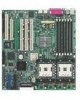
... Package contents Check your PU-DLS package for the following items. ASUS PU-DLS motherboard Extended ATX form factor: 12 in x 13 in (30.5 cm x 33 cm) ASUS PU-DLS support CD I/O shield 80-conductor ribbon cable for UltraDMA100/66/33 IDE drives Ribbon cable for buying the ASUS® PU-DLS motherboard! The ASUS PU-DLS motherboard delivers a host of new... 533) chipset to deliver a reliable and high performance dual-processor server platform. Thank you start installing the motherboard, and hardware devices on it another standout in your retailer. ASUS PU-DLS motherboard user guide 1-1
... Package contents Check your PU-DLS package for the following items. ASUS PU-DLS motherboard Extended ATX form factor: 12 in x 13 in (30.5 cm x 33 cm) ASUS PU-DLS support CD I/O shield 80-conductor ribbon cable for UltraDMA100/66/33 IDE drives Ribbon cable for buying the ASUS® PU-DLS motherboard! The ASUS PU-DLS motherboard delivers a host of new... 533) chipset to deliver a reliable and high performance dual-processor server platform. Thank you start installing the motherboard, and hardware devices on it another standout in your retailer. ASUS PU-DLS motherboard user guide 1-1
PU-DLS User Manual
Page 16
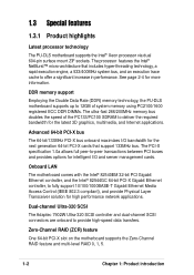
...latest 3D graphics, multimedia, and Internet applications. DDR memory support Employing the Double Data Rate (DDR) memory technology, the PU-DLS motherboard supports up to 12GB of system memory using PC2100/1600 registered ECC DDR DIMMs. The ultra-fast 266/200MHz memory bus ... (ZCR) feature One 64-bit PCI-X slot on the motherboard supports the Zero-Channel RAID feature and multi-level RAID 0, 1, 5. 1-2 Chapter 1: Product introduction 1.3 Special features 1.3.1 Product highlights Latest processor technology The PU-DLS motherboard supports the Intel® Xeon processor via dual 604-pin surface...
...latest 3D graphics, multimedia, and Internet applications. DDR memory support Employing the Double Data Rate (DDR) memory technology, the PU-DLS motherboard supports up to 12GB of system memory using PC2100/1600 registered ECC DDR DIMMs. The ultra-fast 266/200MHz memory bus ... (ZCR) feature One 64-bit PCI-X slot on the motherboard supports the Zero-Channel RAID feature and multi-level RAID 0, 1, 5. 1-2 Chapter 1: Product introduction 1.3 Special features 1.3.1 Product highlights Latest processor technology The PU-DLS motherboard supports the Intel® Xeon processor via dual 604-pin surface...
PU-DLS User Manual
Page 17
ASUS PU-DLS motherboard user guide 1-3 ATA/100 IDE support The dual-channel bus master IDE connectors comply with the ATA/100 protocol and supports ATA/100, Multi-Word DMA Mode2, PIO modes 3 & 4 IDE devices such as ATAPI IDE CD-ROM, CD-R/RW, ZIP, and LS-120 drives.
ASUS PU-DLS motherboard user guide 1-3 ATA/100 IDE support The dual-channel bus master IDE connectors comply with the ATA/100 protocol and supports ATA/100, Multi-Word DMA Mode2, PIO modes 3 & 4 IDE devices such as ATAPI IDE CD-ROM, CD-R/RW, ZIP, and LS-120 drives.

PU-DLS User Manual
Page 18
...Wake-On-LAN, Wake-On-Ring, and BIOS Wake-Up features. Concurrent PCI This feature allows multiple PCI transfers from PCI master buses to the motherboard. The BIOS has a boot block write protection and HD/SCSI/MO/ZIP/CD/Floppy boot selection, and is monitored for less than 4 seconds lets...circuitry logs "chassis-open" events into the system BIOS. 1.3.2 Value-added solutions Temperature, fan, and voltage monitoring The CPU temperature is monitored by the ASUS ASIC to ensure stable supply of the BIOS setting. The system voltage levels are monitored to prevent overheating and damage.
...Wake-On-LAN, Wake-On-Ring, and BIOS Wake-Up features. Concurrent PCI This feature allows multiple PCI transfers from PCI master buses to the motherboard. The BIOS has a boot block write protection and HD/SCSI/MO/ZIP/CD/Floppy boot selection, and is monitored for less than 4 seconds lets...circuitry logs "chassis-open" events into the system BIOS. 1.3.2 Value-added solutions Temperature, fan, and voltage monitoring The CPU temperature is monitored by the ASUS ASIC to ensure stable supply of the BIOS setting. The system voltage levels are monitored to prevent overheating and damage.

PU-DLS User Manual
Page 19
Color-coded connectors and descriptive icons make identification easy as required by the PC '99 specification. ASUS PU-DLS motherboard user guide 1-5 Compliance Both the BIOS and the hardware levels of the motherboard meet the stringent requirements for Windows NT/2000/XP. The new SDG 2.0 requirements for systems and components are based on the following high-level goals: support for Plug-and-Play compatibility and power management for configuring and managing all system components, 32-bit device drivers, and installation procedures for SDG 2.0 certification.
Color-coded connectors and descriptive icons make identification easy as required by the PC '99 specification. ASUS PU-DLS motherboard user guide 1-5 Compliance Both the BIOS and the hardware levels of the motherboard meet the stringent requirements for Windows NT/2000/XP. The new SDG 2.0 requirements for systems and components are based on the following high-level goals: support for Plug-and-Play compatibility and power management for configuring and managing all system components, 32-bit device drivers, and installation procedures for SDG 2.0 certification.

PU-DLS User Manual
Page 20
... yourself with its components. 1.4.1 Major components The following are the major components of the PU-DLS motherboard as pointed out in the picture on the components. 1-6 Chapter 1: Product introduction Intel® P64H2 PCI-X Hub 5. 604-pin CPU sockets 6. 8-pin 12V SSI ... 2 for the specifications of each component. RJ-45 port (for 32-bit LAN) 25. VGA port 27. SSI-type power connector 2. Firmware hub (FWH) 10. ASUS ASIC 14. ATI Rage-XL VGA controller 19. Serial port (COM1) 28. Adaptec 7902W SCSI controller 9. LPC Super I /O Hub 18. Intel® ICH3-S I /O controller...
... yourself with its components. 1.4.1 Major components The following are the major components of the PU-DLS motherboard as pointed out in the picture on the components. 1-6 Chapter 1: Product introduction Intel® P64H2 PCI-X Hub 5. 604-pin CPU sockets 6. 8-pin 12V SSI ... 2 for the specifications of each component. RJ-45 port (for 32-bit LAN) 25. VGA port 27. SSI-type power connector 2. Firmware hub (FWH) 10. ASUS ASIC 14. ATI Rage-XL VGA controller 19. Serial port (COM1) 28. Adaptec 7902W SCSI controller 9. LPC Super I /O Hub 18. Intel® ICH3-S I /O controller...

PU-DLS User Manual
Page 21
12 3 4 5 6 21 20 19 22 7 8 9 10 11 18 17 16 15 14 13 12 23 29 28 27 26 25 24 ASUS PU-DLS motherboard user guide 1-7
12 3 4 5 6 21 20 19 22 7 8 9 10 11 18 17 16 15 14 13 12 23 29 28 27 26 25 24 ASUS PU-DLS motherboard user guide 1-7

PU-DLS User Manual
Page 23
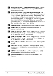
...host controllers, I /O functions. Four 64-bit/100MHz PCI-X slots and two 32-bit/ 33MHz PCI expansion slots support bus master PCI-X/PCI cards. ASUS PU-DLS motherboard user guide 1-9 Both the primary (blue) and secondary (black) connectors are not identical. When lit, this LED (CPULED1) indicates that include hardware... VGA controller supports 8MB display SDRAM for the floppy disk drive. This LED lights up to prevent incorrect insertion of item 7.) 13 ASUS ASIC. These dual-channel bus master IDE connectors support up if there is only one parallel port with EPP and ECP capabilities, a...
...host controllers, I /O functions. Four 64-bit/100MHz PCI-X slots and two 32-bit/ 33MHz PCI expansion slots support bus master PCI-X/PCI cards. ASUS PU-DLS motherboard user guide 1-9 Both the primary (blue) and secondary (black) connectors are not identical. When lit, this LED (CPULED1) indicates that include hardware... VGA controller supports 8MB display SDRAM for the floppy disk drive. This LED lights up to prevent incorrect insertion of item 7.) 13 ASUS ASIC. These dual-channel bus master IDE connectors support up if there is only one parallel port with EPP and ECP capabilities, a...
PU-DLS User Manual
Page 24
.... See section "2.8 Connectors." 28 USB 1.1 ports 1and 2. This LAN controller is also available. These 4-pin Universal Serial Bus (USB) ports are available for LAN on Motherboard (LOM), enterprise networking, and Internet appliances that use a PCI or PCI-X bus.
.... See section "2.8 Connectors." 28 USB 1.1 ports 1and 2. This LAN controller is also available. These 4-pin Universal Serial Bus (USB) ports are available for LAN on Motherboard (LOM), enterprise networking, and Internet appliances that use a PCI or PCI-X bus.
PU-DLS User Manual
Page 25
It includes details on the switch/jumper settings and connector locations on the motherboard. Hardware information Chapter 2 This chapter describes the hardware setup procedures that you have to perform when installing system components.
It includes details on the switch/jumper settings and connector locations on the motherboard. Hardware information Chapter 2 This chapter describes the hardware setup procedures that you have to perform when installing system components.
PU-DLS User Manual
Page 26
Chapter summary 2.1 Motherboard installation 2-1 2.2 Motherboard layout 2-2 2.3 Before you proceed 2-3 2.4 Central Processing Unit (CPU 2-4 2.5 System memory 2-8 2.6 Expansion slots 2-11 2.7 Jumpers 2-14 2.8 Connectors 2-18 ASUS PU-DLS motherboard
Chapter summary 2.1 Motherboard installation 2-1 2.2 Motherboard layout 2-2 2.3 Before you proceed 2-3 2.4 Central Processing Unit (CPU 2-4 2.5 System memory 2-8 2.6 Expansion slots 2-11 2.7 Jumpers 2-14 2.8 Connectors 2-18 ASUS PU-DLS motherboard
PU-DLS User Manual
Page 27
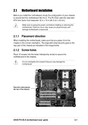
...! The edge with external ports goes to the chassis. The PU-DLS uses the extended ATX form factor that you install the motherboard, study the configuration of the chassis ASUS PU-DLS motherboard user guide 2-1 Doing so may cause you physical injury and damage motherboard components. 2.1.1 Placement direction When installing the motherboard, make sure that measures 12 in x 13 in the...
...! The edge with external ports goes to the chassis. The PU-DLS uses the extended ATX form factor that you install the motherboard, study the configuration of the chassis ASUS PU-DLS motherboard user guide 2-1 Doing so may cause you physical injury and damage motherboard components. 2.1.1 Placement direction When installing the motherboard, make sure that measures 12 in x 13 in the...
PU-DLS User Manual
Page 28
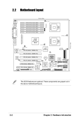
These components are optional. 30.5cm (12in) 2.2 Motherboard layout ® PU-DLS mPGA 604 Socket 1 (u50) J14 PS/2 T: Mouse B: Keyboard USB1 USB2 COM1 33cm (13in...DDR2 (64/72 bit, 184-pin module) DDR1 (64/72 bit, 184-pin module) CPU_FAN1 PARALLEL PORT SSI/ATX POWER VGA RJ-45 (LAN-2) RJ-45 (LAN-1) Intel 82544GC PCI-X Gigabit LAN Intel 82540EM 32-bit Gigabit ...J2 ATI RAGE XL VGA Controller J3 CR2032 3V Lithium Cell CMOS Power Adaptec AIC-7902W SCSI Controller Super I/O ASUS ASIC with Hardware Monitor J4 J6 WOR1 Intel I/O Controller Hub (ICH3-S) FLOPPY1 SCSI-B 34 68 CPULED1 4Mbit...
These components are optional. 30.5cm (12in) 2.2 Motherboard layout ® PU-DLS mPGA 604 Socket 1 (u50) J14 PS/2 T: Mouse B: Keyboard USB1 USB2 COM1 33cm (13in...DDR2 (64/72 bit, 184-pin module) DDR1 (64/72 bit, 184-pin module) CPU_FAN1 PARALLEL PORT SSI/ATX POWER VGA RJ-45 (LAN-2) RJ-45 (LAN-1) Intel 82544GC PCI-X Gigabit LAN Intel 82540EM 32-bit Gigabit ...J2 ATI RAGE XL VGA Controller J3 CR2032 3V Lithium Cell CMOS Power Adaptec AIC-7902W SCSI Controller Super I/O ASUS ASIC with Hardware Monitor J4 J6 WOR1 Intel I/O Controller Hub (ICH3-S) FLOPPY1 SCSI-B 34 68 CPULED1 4Mbit...
PU-DLS User Manual
Page 29
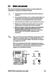
... CPU power fail LED (CPULED1) indicates that the ATX power supply is detached from the wall socket before you install motherboard components or change any motherboard settings. 1. CPULED1 ® PU-DLS PU-DLS Onboard LED ON CPU Failure OFF CPU OK LED1 ON Standby Power OFF Powered Off ASUS PU-DLS motherboard user guide 2-3 Unplug the power cord from the power...
... CPU power fail LED (CPULED1) indicates that the ATX power supply is detached from the wall socket before you install motherboard components or change any motherboard settings. 1. CPULED1 ® PU-DLS PU-DLS Onboard LED ON CPU Failure OFF CPU OK LED1 ON Standby Power OFF Powered Off ASUS PU-DLS motherboard user guide 2-3 Unplug the power cord from the power...


