
PU-DLS User Manual
Page 15
1.1 Welcome! The PU-DLS incorporates dual Intel® Xeon™ processors in 604-pin package coupled with the list below. 1.2 Package contents Check your PU-DLS package for the following items. ASUS PU-DLS motherboard Extended ATX form factor: 12 in x 13 in (30.5 cm x 33 cm) ASUS PU-DLS support CD I/O shield 80-conductor ribbon cable for UltraDMA100/66/33 IDE drives Ribbon cable for buying the ASUS® PU-DLS motherboard! ASUS PU-DLS motherboard user guide 1-1 The ASUS PU-DLS motherboard delivers a host of...
1.1 Welcome! The PU-DLS incorporates dual Intel® Xeon™ processors in 604-pin package coupled with the list below. 1.2 Package contents Check your PU-DLS package for the following items. ASUS PU-DLS motherboard Extended ATX form factor: 12 in x 13 in (30.5 cm x 33 cm) ASUS PU-DLS support CD I/O shield 80-conductor ribbon cable for UltraDMA100/66/33 IDE drives Ribbon cable for buying the ASUS® PU-DLS motherboard! ASUS PU-DLS motherboard user guide 1-1 The ASUS PU-DLS motherboard delivers a host of...
PU-DLS User Manual
Page 16
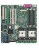
... processor via dual 604-pin surface mount ZIF sockets. DDR memory support Employing the Double Data Rate (DDR) memory technology, the PU-DLS motherboard supports up to 12GB of system memory using PC2100/1600 registered ECC DDR DIMMs. The ultra-fast 266/200MHz memory bus doubles the speed of the PC133/PC100 SDRAM to offer a significant increase in performance. Onboard LAN The motherboard comes with the Intel® 82540EM 32-bit PCI...
... processor via dual 604-pin surface mount ZIF sockets. DDR memory support Employing the Double Data Rate (DDR) memory technology, the PU-DLS motherboard supports up to 12GB of system memory using PC2100/1600 registered ECC DDR DIMMs. The ultra-fast 266/200MHz memory bus doubles the speed of the PC133/PC100 SDRAM to offer a significant increase in performance. Onboard LAN The motherboard comes with the Intel® 82540EM 32-bit PCI...

PU-DLS User Manual
Page 19
Color-coded connectors and descriptive icons make identification easy as required by the PC '99 specification. Compliance Both the BIOS and the hardware levels of the motherboard meet the stringent requirements for Windows NT/2000/XP. ASUS PU-DLS motherboard user guide 1-5 The new SDG 2.0 requirements for systems and components are based on the following high-level goals: support for Plug-and-Play compatibility and power management for configuring and managing all system components, 32-bit device drivers, and installation procedures for SDG 2.0 certification.
Color-coded connectors and descriptive icons make identification easy as required by the PC '99 specification. Compliance Both the BIOS and the hardware levels of the motherboard meet the stringent requirements for Windows NT/2000/XP. ASUS PU-DLS motherboard user guide 1-5 The new SDG 2.0 requirements for systems and components are based on the following high-level goals: support for Plug-and-Play compatibility and power management for configuring and managing all system components, 32-bit device drivers, and installation procedures for SDG 2.0 certification.

PU-DLS User Manual
Page 23
... ATA/100 bus master IDE controller, integrated LAN controllers, three Universal Host Controller Interface (UHCI) USB 1.1compliant host controllers, I /O controller. This PCI-based VGA controller supports 8MB display SDRAM for the floppy disk drive. 10 IDE connectors. This chip performs multiple system functions that the CPUs installed on the motherboard, and serves as a reminder to prevent incorrect insertion of the IDE ribbon cable. 11 Standby power LED. The chipset supports UART compatible serial ports, one CPU. 15 LPC super I /O APIC, SMBus Specification Rev...
... ATA/100 bus master IDE controller, integrated LAN controllers, three Universal Host Controller Interface (UHCI) USB 1.1compliant host controllers, I /O controller. This PCI-based VGA controller supports 8MB display SDRAM for the floppy disk drive. 10 IDE connectors. This chip performs multiple system functions that the CPUs installed on the motherboard, and serves as a reminder to prevent incorrect insertion of the IDE ribbon cable. 11 Standby power LED. The chipset supports UART compatible serial ports, one CPU. 15 LPC super I /O APIC, SMBus Specification Rev...
PU-DLS User Manual
Page 27
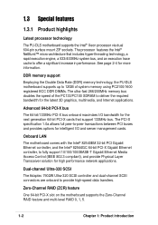
... circles to secure the motherboard to the rear part of the chassis ASUS PU-DLS motherboard user guide 2-1 Failure to unplug the power cord before installing or removing the motherboard. 2.1 Motherboard installation Before you place it . Place this side towards the rear of the chassis as indicated in (30.5 cm x 33 cm). The PU-DLS uses the extended ATX form factor that the motherboard fits into it into the chassis in the correct orientation...
... circles to secure the motherboard to the rear part of the chassis ASUS PU-DLS motherboard user guide 2-1 Failure to unplug the power cord before installing or removing the motherboard. 2.1 Motherboard installation Before you place it . Place this side towards the rear of the chassis as indicated in (30.5 cm x 33 cm). The PU-DLS uses the extended ATX form factor that the motherboard fits into it into the chassis in the correct orientation...
PU-DLS User Manual
Page 29
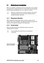
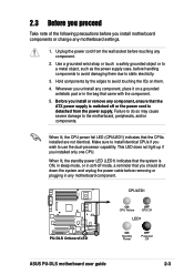
... strap or touch a safely grounded object or to a metal object, such as the power supply case, before handling components to static electricity. 3. Make sure to use the dual-processor capability. CPULED1 ® PU-DLS PU-DLS Onboard LED ON CPU Failure OFF CPU OK LED1 ON Standby Power OFF Powered Off ASUS PU-DLS motherboard user guide 2-3 This LED does not light up if you wish to install identical CPUs if you installed only one CPU. Whenever you uninstall...
... strap or touch a safely grounded object or to a metal object, such as the power supply case, before handling components to static electricity. 3. Make sure to use the dual-processor capability. CPULED1 ® PU-DLS PU-DLS Onboard LED ON CPU Failure OFF CPU OK LED1 ON Standby Power OFF Powered Off ASUS PU-DLS motherboard user guide 2-3 This LED does not light up if you wish to install identical CPUs if you installed only one CPU. Whenever you uninstall...
PU-DLS User Manual
Page 35
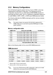
... table). Installed - - 2.5.2 Memory Configurations The motherboard supports system memory of up to 12GB in pairs. Installed DDR2 - - - - - The system chipset only supports PC2100/1600 registered ECC DIMMs. Make sure to install identical (the same type and size) DDR DIMM pairs. DIMM placement One-DIMM * Two-DIMM ** Two-DIMM * Three-DIMM * Four-DIMM ** Six-DIMM ** DDR1 - - - Installed Installed * Memory width is 128-bit; Installed - Installed DDR3 - - ASUS PU-DLS motherboard user guide 2-9 low performance ** Memory width...
... table). Installed - - 2.5.2 Memory Configurations The motherboard supports system memory of up to 12GB in pairs. Installed DDR2 - - - - - The system chipset only supports PC2100/1600 registered ECC DIMMs. Make sure to install identical (the same type and size) DDR DIMM pairs. DIMM placement One-DIMM * Two-DIMM ** Two-DIMM * Three-DIMM * Four-DIMM ** Six-DIMM ** DDR1 - - - Installed Installed * Memory width is 128-bit; Installed - Installed DDR3 - - ASUS PU-DLS motherboard user guide 2-9 low performance ** Memory width...
PU-DLS User Manual
Page 37
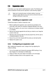
... on BIOS setup. 2. Secure the card to the chassis with the slot and press firmly until the card is already installed in a chassis). 3. ASUS PU-DLS motherboard user guide 2-11 Remove the bracket opposite the slot that came with it by adjusting the software settings. 1. Refer to the tables on the system and change the necessary BIOS settings, if any. Keep the screw for the card. 2. Turn on the next page. 3. Install the software drivers for...
... on BIOS setup. 2. Secure the card to the chassis with the slot and press firmly until the card is already installed in a chassis). 3. ASUS PU-DLS motherboard user guide 2-11 Remove the bracket opposite the slot that came with it by adjusting the software settings. 1. Refer to the tables on the system and change the necessary BIOS settings, if any. Keep the screw for the card. 2. Turn on the next page. 3. Install the software drivers for...
PU-DLS User Manual
Page 41
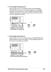
...and devices that use PCI or PCI-X bus. Set to pins 2-3 to enable the onboard Intel® 82544GC Gigabit Ethernet controller. Set to pins 2-3 to disable the controller. ® PU-DLS PU-DLS 64BIT 1G LAN Setting J15 12 23 Enable (Default) Disable 4. 32-bit Gigabit LAN setting (J1) Set this jumper to pins 1-2 to disable the controller. ® PU-DLS J1 12 23 Enable (Default) Disable PU-DLS Intel 82540 LAN Chip Setting ASUS PU-DLS motherboard user guide 2-15 This controller supports up to enable the onboard Intel 82540EM 32-bit Gigabit Ethernet controller and support 10...
...and devices that use PCI or PCI-X bus. Set to pins 2-3 to enable the onboard Intel® 82544GC Gigabit Ethernet controller. Set to pins 2-3 to disable the controller. ® PU-DLS PU-DLS 64BIT 1G LAN Setting J15 12 23 Enable (Default) Disable 4. 32-bit Gigabit LAN setting (J1) Set this jumper to pins 1-2 to disable the controller. ® PU-DLS J1 12 23 Enable (Default) Disable PU-DLS Intel 82540 LAN Chip Setting ASUS PU-DLS motherboard user guide 2-15 This controller supports up to enable the onboard Intel 82540EM 32-bit Gigabit Ethernet controller and support 10...

PU-DLS User Manual
Page 42
Onboard VGA setting (J2) This jumper allows you wish to install a VGA card. Set to pins 2-3 to enable or disbale the onboard VGA feature. Set to pins 1-2 to disable the onboard VGA controller if you to enable the wake-up feature. Set to pins 2-3 to disable the keyboard wake-up feature. ® PU-DLS J14 12 23 Disable (Default) Enable PU-DLS Keyboard WAKE-UP Setting 6. Keyboard wake-up setting (J14) Set this jumper to pins 1-2 to enable the onboard VGA feature. ® PU-DLS PU-DLS ATI RageXL VGA Setting J2 1 2 Disable 2 3 Enable (Default) 2-16 Chapter 2: Hardware ...
Onboard VGA setting (J2) This jumper allows you wish to install a VGA card. Set to pins 2-3 to enable or disbale the onboard VGA feature. Set to pins 1-2 to disable the onboard VGA controller if you to enable the wake-up feature. Set to pins 2-3 to disable the keyboard wake-up feature. ® PU-DLS J14 12 23 Disable (Default) Enable PU-DLS Keyboard WAKE-UP Setting 6. Keyboard wake-up setting (J14) Set this jumper to pins 1-2 to enable the onboard VGA feature. ® PU-DLS PU-DLS ATI RageXL VGA Setting J2 1 2 Disable 2 3 Enable (Default) 2-16 Chapter 2: Hardware ...

PU-DLS User Manual
Page 55
... working Meaning No error during POST No DRAM installed or detected Video card not found or video card memory bad CPU overheated; Turn on . For ATX power supplies, the system LED lights up . The system then runs the power-on the system front panel case lights up when you press the ATX power switch. Award BIOS Beep Codes Beep One short beep when displaying logo Long beeps in an endless loop One long beep followed by three short beeps High frequency beeps when system is equipped with a surge protector. 5. Follow the instructions...
... working Meaning No error during POST No DRAM installed or detected Video card not found or video card memory bad CPU overheated; Turn on . For ATX power supplies, the system LED lights up . The system then runs the power-on the system front panel case lights up when you press the ATX power switch. Award BIOS Beep Codes Beep One short beep when displaying logo Long beeps in an endless loop One long beep followed by three short beeps High frequency beeps when system is equipped with a surge protector. 5. Follow the instructions...
PU-DLS User Manual
Page 74
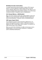
... options: [Disabled] [Enabled] [Auto] 4-16 Chapter 4: BIOS Setup If not detected, the USB controller legacy mode is enabled. If detected, the USB controller legacy mode is disabled. If a mouse is detected at startup. Configuration options: [Disabled] [Enabled] USB Legacy Support [Auto] This motherboard supports Universal Serial Bus (USB) devices. PS/2 Mouse Function Control [Auto] The default setting [Auto] allows the system to [Enabled]. Configuration options: [Enabled] [Auto] OS/2 Onboard Memory > 64M [Disabled] When using a USB device. When you need to set this option...
... options: [Disabled] [Enabled] [Auto] 4-16 Chapter 4: BIOS Setup If not detected, the USB controller legacy mode is enabled. If detected, the USB controller legacy mode is disabled. If a mouse is detected at startup. Configuration options: [Disabled] [Enabled] USB Legacy Support [Auto] This motherboard supports Universal Serial Bus (USB) devices. PS/2 Mouse Function Control [Auto] The default setting [Auto] allows the system to [Enabled]. Configuration options: [Enabled] [Auto] OS/2 Onboard Memory > 64M [Disabled] When using a USB device. When you need to set this option...

PU-DLS User Manual
Page 79
... will be used. stability. Configuration options: [Auto] [Disabled] Primary VGA BIOS First [PCI VGA Card] This field allows you wish to detect whether you are using the onboard LAN controller boot ROM. If your SCSI card does not have a Adaptec SCSI controller. Configuration options: [Disabled] [Enabled] ASUS PU-DLS motherboard user guide 4-21 Configuration options: [Disabled] [3 Controllers] ONB Intel 82544 LAN Boot ROM [Disabled] ONB Intel 82540 LAN Boot ROM [Disabled] When set to [Enabled], these fields allow the system to select the number of USB 1.1 controllers that the...
... will be used. stability. Configuration options: [Auto] [Disabled] Primary VGA BIOS First [PCI VGA Card] This field allows you wish to detect whether you are using the onboard LAN controller boot ROM. If your SCSI card does not have a Adaptec SCSI controller. Configuration options: [Disabled] [Enabled] ASUS PU-DLS motherboard user guide 4-21 Configuration options: [Disabled] [3 Controllers] ONB Intel 82544 LAN Boot ROM [Disabled] ONB Intel 82540 LAN Boot ROM [Disabled] When set to [Enabled], these fields allow the system to select the number of USB 1.1 controllers that the...

PU-DLS User Manual
Page 83
... Soft-off . [Previous State] sets the system back to turn on . Configuration options: [Disabled] [Enabled] The computer cannot receive or transmit data until the computer and applications are fully running. Configuration options: [Disabled] [Enabled] ASUS PU-DLS motherboard user guide 4-25 4.5.1 Power Up Control AC PWR Loss Restart [Disabled] This allows you to the state it was before the power interruption. Power Up On PCI Device [Disabled] When set to [Enabled], this parameter allows you to...
... Soft-off . [Previous State] sets the system back to turn on . Configuration options: [Disabled] [Enabled] The computer cannot receive or transmit data until the computer and applications are fully running. Configuration options: [Disabled] [Enabled] ASUS PU-DLS motherboard user guide 4-25 4.5.1 Power Up Control AC PWR Loss Restart [Disabled] This allows you to the state it was before the power interruption. Power Up On PCI Device [Disabled] When set to [Enabled], this parameter allows you to...

PU-DLS User Manual
Page 87
... controller. BEV devices include network controllers or cards. This mode does not allow the operation to continue or use a Plug-and-Play (PnP) operating system to assign a device as options for a specific application, you must set boot virus detection, ensuring a virus-free boot sector. The system halts and displays a warning message when it was configured the last time it detects a virus. Configuration options: [Disabled] [Enabled] ASUS PU-DLS motherboard user guide 4-29 If you to use a virus-free bootable floppy disk...
... controller. BEV devices include network controllers or cards. This mode does not allow the operation to continue or use a Plug-and-Play (PnP) operating system to assign a device as options for a specific application, you must set boot virus detection, ensuring a virus-free boot sector. The system halts and displays a warning message when it was configured the last time it detects a virus. Configuration options: [Disabled] [Enabled] ASUS PU-DLS motherboard user guide 4-29 If you to use a virus-free bootable floppy disk...
PU-DLS User Manual
Page 93
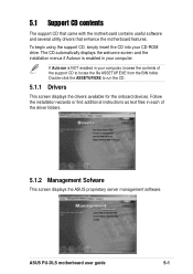
... driver folders. 5.1.2 Management Sofware This screen displays the ASUS proprietary server management software. If Autorun is enabled in each of the support CD to run the CD. 5.1.1 Drivers This screen displays the drivers available for the onboard devices. Follow the installation wizards or find additional instructions as text files in your CD-ROM drive. ASUS PU-DLS motherboard user guide 5-1 5.1 Support CD contents The support CD that came with the motherboard contains useful software and several utility drivers that enhance the motherboard...
... driver folders. 5.1.2 Management Sofware This screen displays the ASUS proprietary server management software. If Autorun is enabled in each of the support CD to run the CD. 5.1.1 Drivers This screen displays the drivers available for the onboard devices. Follow the installation wizards or find additional instructions as text files in your CD-ROM drive. ASUS PU-DLS motherboard user guide 5-1 5.1 Support CD contents The support CD that came with the motherboard contains useful software and several utility drivers that enhance the motherboard...
PU-DLS User Manual
Page 96
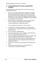
... Cards (WinNT 4.0) and press Enter. 7. Installing Windows NT 4.0 with the Windows NT 4.0 Boot disk in the floppy disk drive or the Windows NT 4.0 Boot CD-ROM in the Windows NT 4.0 documentation to install Windows NT 4.0 for more information. 2. Start your computer system's hardware." NOTE: If there is inspecting your system with an Ultra320 SCSI Controller Follow these steps to complete the installation. 5-4 Chapter 5: Driver installation "Setup is DOS installed and you are installing from floppy disk...
... Cards (WinNT 4.0) and press Enter. 7. Installing Windows NT 4.0 with the Windows NT 4.0 Boot disk in the floppy disk drive or the Windows NT 4.0 Boot CD-ROM in the Windows NT 4.0 documentation to install Windows NT 4.0 for more information. 2. Start your computer system's hardware." NOTE: If there is inspecting your system with an Ultra320 SCSI Controller Follow these steps to complete the installation. 5-4 Chapter 5: Driver installation "Setup is DOS installed and you are installing from floppy disk...
PU-DLS User Manual
Page 105
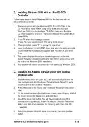
... start the Found New Hardware Wizard to guide you to insert the manufacturer supplied disk. ASUS PU-DLS motherboard user guide 5-13 Your system will be prompted to insert the manufacturer supplied disk into drive A, and press Enter. 5. Select the Have Disk button. Select "Adaptec Ultra320 SCSI Cards (Win2000)" and continue with existing Windows 2000 1. You will reboot once more to install third-party SCSI drivers" 3. Press F6 when this device...
... start the Found New Hardware Wizard to guide you to insert the manufacturer supplied disk. ASUS PU-DLS motherboard user guide 5-13 Your system will be prompted to insert the manufacturer supplied disk into drive A, and press Enter. 5. Select the Have Disk button. Select "Adaptec Ultra320 SCSI Cards (Win2000)" and continue with existing Windows 2000 1. You will reboot once more to install third-party SCSI drivers" 3. Press F6 when this device...
PU-DLS User Manual
Page 116
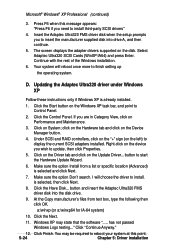
... the manufacturer supplied disk into the disk drive. 9. I will reboot once more to install. You may state that the software "..... Updating the Adaptec Ultra320 driver under Windows XP Follow these instructions only if Windows XP is selected, then click Next. 8. Make sure the option Install from text box, type the following then click OK. Click on the disk. At the Copy manufacturer's files from a list or specific location (Advanced...
... the manufacturer supplied disk into the disk drive. 9. I will reboot once more to install. You may state that the software "..... Updating the Adaptec Ultra320 driver under Windows XP Follow these instructions only if Windows XP is selected, then click Next. 8. Make sure the option Install from text box, type the following then click OK. Click on the disk. At the Copy manufacturer's files from a list or specific location (Advanced...

PU-DLS User Manual
Page 122
You do not need to load any driver for supporting the onboard ATI RAGE XL graphics controller chipset. 5-30 Chapter 5: Driver installation Microsoft® Windows® XP Professional (continued) 5.4.3 ATI® Rage XL Display Driver Installation Windows XP system can automatically recognize the ATI RAGE XL PCI driver during system installation.
You do not need to load any driver for supporting the onboard ATI RAGE XL graphics controller chipset. 5-30 Chapter 5: Driver installation Microsoft® Windows® XP Professional (continued) 5.4.3 ATI® Rage XL Display Driver Installation Windows XP system can automatically recognize the ATI RAGE XL PCI driver during system installation.


