User Manual
Page 25
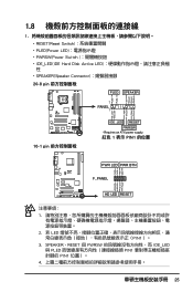
PWR Ground Reset Ground 10-1 pin IDE_LED RESET PWRSW * Requires an ATX power supply. 紅色 1 表示 PIN1 的位置 PLED+ PLEDPWR GND IDELED+ IDELED- Ground Reset PWR LED PWR BTN M2N-X F_PANEL HD LED ...
PWR Ground Reset Ground 10-1 pin IDE_LED RESET PWRSW * Requires an ATX power supply. 紅色 1 表示 PIN1 的位置 PLED+ PLEDPWR GND IDELED+ IDELED- Ground Reset PWR LED PWR BTN M2N-X F_PANEL HD LED ...
User Manual
Page 26
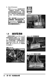
Asus Q-Connector 華碩 Q-Connector Q-Connector Q-Connector Q-Connector 1.9 24-pin 或 20-pin 24-pin 4-pin 的 ATX+12V 連接 ATX12V 24-pin ATX 20- 2. pin ATX 26
Asus Q-Connector 華碩 Q-Connector Q-Connector Q-Connector Q-Connector 1.9 24-pin 或 20-pin 24-pin 4-pin 的 ATX+12V 連接 ATX12V 24-pin ATX 20- 2. pin ATX 26

User Manual
Page 13
xiii P5N-D�s�p��e�c�if�ic�a��ti�o�n�s��s�u�m��m�a��... Front panel audio connector 1 x S/PDIF Out Header Chassis Intrusion connector CD audio in 24-pin ATX Power connector 4-pin ATX 12V Power connector System Panel (Q-Connector) 8 Mb Flash ROM, AWARD BIOS, PnP, DMI2.0, WfM2.0, SM BIOS 2.4, ASUS EZ Flash 2, ASUS CrashFree BIOS 2 WfM 2.0, DMI 2.0 , WOR by Ring , WOL/WOR by PME, WO USB/KB...
xiii P5N-D�s�p��e�c�if�ic�a��ti�o�n�s��s�u�m��m�a��... Front panel audio connector 1 x S/PDIF Out Header Chassis Intrusion connector CD audio in 24-pin ATX Power connector 4-pin ATX 12V Power connector System Panel (Q-Connector) 8 Mb Flash ROM, AWARD BIOS, PnP, DMI2.0, WfM2.0, SM BIOS 2.4, ASUS EZ Flash 2, ASUS CrashFree BIOS 2 WfM 2.0, DMI 2.0 , WOR by Ring , WOL/WOR by PME, WO USB/KB...
User Manual
Page 25
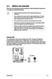
...ATX power supply is switched off or the power cord is ON, in sleep mode, or in soft‑off mode. 2.1 Before you proceed Take note of the onboard LED. ® P5N-D P5N-D Onboard LED SB_PWR ON Standby Power OFF Powered Off ASUS P5N-D 2-1 Onboard LED The motherboard... comes with the component. • Before you install motherboard components or change any motherboard settings. • Unplug the power cord from the power ...
...ATX power supply is switched off or the power cord is ON, in sleep mode, or in soft‑off mode. 2.1 Before you proceed Take note of the onboard LED. ® P5N-D P5N-D Onboard LED SB_PWR ON Standby Power OFF Powered Off ASUS P5N-D 2-1 Onboard LED The motherboard... comes with the component. • Before you install motherboard components or change any motherboard settings. • Unplug the power cord from the power ...

User Manual
Page 48
... from S1 sleep mode (CPU stopped, DRAM refreshed, system running in low power mode) using the connected USB devices. This feature requires an ATX power supply that can supply at least 500 mA on the keyboard (the default is the Space Bar). The USBPW1-4 jumpers are for each... Set these jumpers to +5V to wake up the computer when you to additional USB ports. 2. USBPW1-4 2 1 +5V (Default) 3 2 +5VSB ® P5N-D USBPW5-8 12 23 +5V P5N-D USB device wake up (Default) +5VSB • The USB device wake-up feature requires a power supply that you can provide 500mA on the...
... from S1 sleep mode (CPU stopped, DRAM refreshed, system running in low power mode) using the connected USB devices. This feature requires an ATX power supply that can supply at least 500 mA on the keyboard (the default is the Space Bar). The USBPW1-4 jumpers are for each... Set these jumpers to +5V to wake up the computer when you to additional USB ports. 2. USBPW1-4 2 1 +5V (Default) 3 2 +5VSB ® P5N-D USBPW5-8 12 23 +5V P5N-D USB device wake up (Default) +5VSB • The USB device wake-up feature requires a power supply that you can provide 500mA on the...
User Manual
Page 55
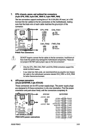
... ® P5N-D ATX12V +12V DC GND +12V DC GND P5N-D ATX power connectors EATXPWR +3 Volts +12 Volts +12 Volts +5V Standby Power OK Ground +5 Volts Ground +5 Volts Ground +3 Volts +3 Volts Ground +5 Volts +5 Volts +5 Volts -5 Volts Ground Ground Ground PSON# Ground -12 Volts +3 Volts ASUS P5N-D 2-31... connectors in only one orientation. Connect the fan cables to the motherboard connector labeled CHA_FAN1 or CHA_FAN2 for ATX power supply plugs. Insufficient air flow inside the system may damage the motherboard components. These are for better thermal environment. 8. DO NOT place...
... ® P5N-D ATX12V +12V DC GND +12V DC GND P5N-D ATX power connectors EATXPWR +3 Volts +12 Volts +12 Volts +5V Standby Power OK Ground +5 Volts Ground +5 Volts Ground +3 Volts +3 Volts Ground +5 Volts +5 Volts +5 Volts -5 Volts Ground Ground Ground PSON# Ground -12 Volts +3 Volts ASUS P5N-D 2-31... connectors in only one orientation. Connect the fan cables to the motherboard connector labeled CHA_FAN1 or CHA_FAN2 for ATX power supply plugs. Insufficient air flow inside the system may damage the motherboard components. These are for better thermal environment. 8. DO NOT place...
User Manual
Page 56
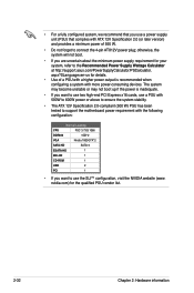
... use a PSU with 500W to 600W power or above to ensure the system stability. • The ATX 12V Specification 2.0-compliant (500 W) PSU has been tested to support the motherboard power requirement with more power-consuming devices. The system may become unstable or may not boot up if...to connect the 4-pin ATX12V power plug; nvidia.com) for your system, refer to the Recommended Power Supply Wattage Calculator at http://support.asus.com/PowerSupplyCalculator/PSCalculator. otherwise, the system will not boot. • If you are uncertain about the minimum power supply requirement for the ...
... use a PSU with 500W to 600W power or above to ensure the system stability. • The ATX 12V Specification 2.0-compliant (500 W) PSU has been tested to support the motherboard power requirement with more power-consuming devices. The system may become unstable or may not boot up if...to connect the 4-pin ATX12V power plug; nvidia.com) for your system, refer to the Recommended Power Supply Wattage Calculator at http://support.asus.com/PowerSupplyCalculator/PSCalculator. otherwise, the system will not boot. • If you are uncertain about the minimum power supply requirement for the ...

User Manual
Page 58
P5N-D System panel connector • System power LED (2-pin PLED) This 2-pin connector is for the system power button. Connect the HDD Activity LED cable to hear system beeps and warnings. • ATX power button/soft-off mode depending on the system power, and blinks when the system ...is in sleep or soft-off button (2-pin PWR) This connector is for the chassis-mounted system warning speaker. PLED+ PLED+5V Ground Ground Speaker ® P5N-D IDE_LED+ IDE_LED- ...
P5N-D System panel connector • System power LED (2-pin PLED) This 2-pin connector is for the system power button. Connect the HDD Activity LED cable to hear system beeps and warnings. • ATX power button/soft-off mode depending on the system power, and blinks when the system ...is in sleep or soft-off button (2-pin PWR) This connector is for the chassis-mounted system warning speaker. PLED+ PLED+5V Ground Ground Speaker ® P5N-D IDE_LED+ IDE_LED- ...

User Manual
Page 63
External SCSI devices (starting with a surge protector. 5. If your retailer for the first time 1. While the tests are off. 3. ASUS�P�5�N��-D� 3-1 Be sure that is equipped with the last device on self tests or POST. Monitor b. The system then... switches are running, the BIOS beeps (see anything within 30 seconds from the time you press the ATX power button. Check the jumper settings and connections or call your monitor complies with ATX power supplies, the system LED lights up when you turned on the power, the system may light ...
External SCSI devices (starting with a surge protector. 5. If your retailer for the first time 1. While the tests are off. 3. ASUS�P�5�N��-D� 3-1 Be sure that is equipped with the last device on self tests or POST. Monitor b. The system then... switches are running, the BIOS beeps (see anything within 30 seconds from the time you press the ATX power button. Check the jumper settings and connections or call your monitor complies with ATX power supplies, the system LED lights up when you turned on the power, the system may light ...

User Manual
Page 98
...;C�]��[P��o�w��e�r�K��e�y�] 4-32 Chapter 4: BIOS setup This feature requires an ATX power supply that provides at least 1A on the +5VSB lead. Key-in a value within the specified range then press . Configuration ..., highlight this item and press to increase the performance of the Vista Multimedia player and can meet Vista's requirement. This feature requires an ATX power supply that provides at least 1A on the +5VSB lead. Configuration options: [Min=0] [Max=31] Alarm Time (hh:mm) ...
...;C�]��[P��o�w��e�r�K��e�y�] 4-32 Chapter 4: BIOS setup This feature requires an ATX power supply that provides at least 1A on the +5VSB lead. Key-in a value within the specified range then press . Configuration ..., highlight this item and press to increase the performance of the Vista Multimedia player and can meet Vista's requirement. This feature requires an ATX power supply that provides at least 1A on the +5VSB lead. Configuration options: [Min=0] [Max=31] Alarm Time (hh:mm) ...

User Manual
Page 156
Refer to the PSU documentation for better thermal environment. 6-4 Chapter 6: NVIDIA® SLI™ technology support When installing two VGA cards using a 20-pin ATX PSU with sufficient+12v capability, we recommend that the connector is firmly in place. We recommend to the graphics card/s. 5. Align and insert the SLI ...
Refer to the PSU documentation for better thermal environment. 6-4 Chapter 6: NVIDIA® SLI™ technology support When installing two VGA cards using a 20-pin ATX PSU with sufficient+12v capability, we recommend that the connector is firmly in place. We recommend to the graphics card/s. 5. Align and insert the SLI ...

