User Manual
Page 9
... documentation, such as warranty flyers, that the motherboard supports. Detailed descriptions of the BIOS parameters are not part of the standard package. Optional documentation Your product package may have to the ASUS contact information. 2. ix Where to find more information Refer to change system settings through the BIOS Setup menus. About this guide is organized...
... documentation, such as warranty flyers, that the motherboard supports. Detailed descriptions of the BIOS parameters are not part of the standard package. Optional documentation Your product package may have to the ASUS contact information. 2. ix Where to find more information Refer to change system settings through the BIOS Setup menus. About this guide is organized...
User Manual
Page 21
...the motherboard. See page 5-25 for details. This unique module eliminates the trouble of data via the network cable - ASUS Q-Connector ASUS Q-Connector allows you to install computer components, update the BIOS or back up to conveniently store or load multiple BIOS settings. ASUS EZ DIY ASUS EZ... DIY feature collection provides you easy ways to restore the original BIOS data from the support CD when the BIOS codes and data are corrupted. See page 4-9 for details. ASUS P5N-D 1-5 With AI Direct Link...
...the motherboard. See page 5-25 for details. This unique module eliminates the trouble of data via the network cable - ASUS Q-Connector ASUS Q-Connector allows you to install computer components, update the BIOS or back up to conveniently store or load multiple BIOS settings. ASUS EZ DIY ASUS EZ... DIY feature collection provides you easy ways to restore the original BIOS data from the support CD when the BIOS codes and data are corrupted. See page 4-9 for details. ASUS P5N-D 1-5 With AI Direct Link...
User Manual
Page 22
... 4-5 and 4-42 for each parameter. 1-6 Chapter 1: Product Introduction The localized BIOS setup menu helps you to select the language of the motherboard BIOS allows automatic re-setting to the BIOS default settings in 0.02v steps to finetune voltages to achieve the most precise setting for details. 1.3.3 ASUS Intelligent Performance and Overclocking features Precision Tweaker 2 Allows the user to...
... 4-5 and 4-42 for each parameter. 1-6 Chapter 1: Product Introduction The localized BIOS setup menu helps you to select the language of the motherboard BIOS allows automatic re-setting to the BIOS default settings in 0.02v steps to finetune voltages to achieve the most precise setting for details. 1.3.3 ASUS Intelligent Performance and Overclocking features Precision Tweaker 2 Allows the user to...
User Manual
Page 43
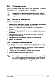
...settings. 1. Assign an IRQ to the tables on the slot. 5. See Chapter 4 for the expansion card. Before installing the expansion card, read the documentation that you intend to unplug the power cord before adding or removing expansion cards. ASUS P5N-D 2-19 Remove the system unit cover (if your motherboard... is completely seated on the next page. 3. Refer to the card. Secure the card to the table on BIOS setup. 2. Install the software drivers ...
...settings. 1. Assign an IRQ to the tables on the slot. 5. See Chapter 4 for the expansion card. Before installing the expansion card, read the documentation that you intend to unplug the power cord before adding or removing expansion cards. ASUS P5N-D 2-19 Remove the system unit cover (if your motherboard... is completely seated on the next page. 3. Refer to the card. Secure the card to the table on BIOS setup. 2. Install the software drivers ...
User Manual
Page 47
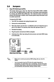
...OFF the computer and unplug the power cord. 2. Hold down and reboot the system so the BIOS can clear the CMOS memory of date, time, and system setup parameters by erasing the CMOS RTC RAM data. ASUS P5N-D 2-23 To erase the RTC RAM: 1. Reinstall the battery. 5. For system failure due to...ON the computer. 6. Shut down the key during the boot process and enter BIOS setup to re-enter data. ® P5N-D P5N-D Clear RTC RAM CLRTC 12 23 Normal Clear RTC (Default) • Make sure to re-enter your previous BIOS settings after you to default values. Clear RTC RAM (3-pin CLRTC) This jumper ...
...OFF the computer and unplug the power cord. 2. Hold down and reboot the system so the BIOS can clear the CMOS memory of date, time, and system setup parameters by erasing the CMOS RTC RAM data. ASUS P5N-D 2-23 To erase the RTC RAM: 1. Reinstall the battery. 5. For system failure due to...ON the computer. 6. Shut down the key during the boot process and enter BIOS setup to re-enter data. ® P5N-D P5N-D Clear RTC RAM CLRTC 12 23 Normal Clear RTC (Default) • Make sure to re-enter your previous BIOS settings after you to default values. Clear RTC RAM (3-pin CLRTC) This jumper ...

User Manual
Page 48
...) 3 2 +5VSB ® P5N-D P5N-D Keyboard power setting 2-24 Chapter 2: Hardware information This feature requires an ATX power supply that you to additional USB ports. Set this jumper to pins 2-3 (+5VSB) to wake up . • The total current consumed must NOT exceed the power supply capability (+5VSB) whether under normal condition or in the BIOS. 2. otherwise, the...
...) 3 2 +5VSB ® P5N-D P5N-D Keyboard power setting 2-24 Chapter 2: Hardware information This feature requires an ATX power supply that you to additional USB ports. Set this jumper to pins 2-3 (+5VSB) to wake up . • The total current consumed must NOT exceed the power supply capability (+5VSB) whether under normal condition or in the BIOS. 2. otherwise, the...

User Manual
Page 52
...65533;�V�I�D��IA�® MediaShield™ RAID controller. ® P5N-D P5N-D SATA connectors SATA1 SATA2 SATA3 SATA4 GND RSATA_TXP1 RSATA_TXN1 GND RSATA_RXP1 RSATA_RXN1 GND GND RSATA_TXP2 ...of these connectors, enable the RAID Enabled item under the Serial ATA Configuration sub-menu in the BIOS. These connectors support Native Command Queuing (NCQ), Power Management (PM) Implementation Algorithm, Hot Swap .... If any device jumper is set using these connectors is set as "Cable-Select," make sure all other device jumpers have the same...
...65533;�V�I�D��IA�® MediaShield™ RAID controller. ® P5N-D P5N-D SATA connectors SATA1 SATA2 SATA3 SATA4 GND RSATA_TXP1 RSATA_TXN1 GND RSATA_RXP1 RSATA_RXN1 GND GND RSATA_TXP2 ...of these connectors, enable the RAID Enabled item under the Serial ATA Configuration sub-menu in the BIOS. These connectors support Native Command Queuing (NCQ), Power Management (PM) Implementation Algorithm, Hot Swap .... If any device jumper is set using these connectors is set as "Cable-Select," make sure all other device jumpers have the same...
User Manual
Page 57
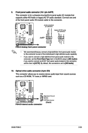
...a CD-ROM, TV tuner, or MPEG card. ® P5N-D CD Right Audio Channel Ground Ground Left Audio Channel P5N-D Internal audio connector (black) ASUS P5N-D 2-33 By default, this connector, set to [HD Audio]; Connect one end of the motherboard's high-definition audio capability. • If you to this ...chassis-mounted front panel audio I /O module cable to this connector, set the Front Panel Type item in the BIOS setup to [HD Audio]. 10. Front panel audio connector (10-1 pin AAFP) This connector is set the item to [AC'97]. Azalia-compliant pin definition Legacy AC'97...
...a CD-ROM, TV tuner, or MPEG card. ® P5N-D CD Right Audio Channel Ground Ground Left Audio Channel P5N-D Internal audio connector (black) ASUS P5N-D 2-33 By default, this connector, set to [HD Audio]; Connect one end of the motherboard's high-definition audio capability. • If you to this ...chassis-mounted front panel audio I /O module cable to this connector, set the Front Panel Type item in the BIOS setup to [HD Audio]. 10. Front panel audio connector (10-1 pin AAFP) This connector is set the item to [AC'97]. Azalia-compliant pin definition Legacy AC'97...

User Manual
Page 58
...pin connector is for the chassis-mounted system warning speaker. Pressing the power button turns the system on the BIOS settings. PLED+ PLED+5V Ground Ground Speaker ® P5N-D IDE_LED+ IDE_LED- P5N-D System panel connector • System power LED (2-pin PLED) This 2-pin connector is for system reboot without...the system power, and blinks when the system is for the HDD Activity LED. PLED SPEAKER PANEL IDE_LED RESET PWRSW * Requires an ATX power supply. System panel connector (20-8 pin PANEL) This connector supports several chassis-mounted functions. The system power LED lights up ...
...pin connector is for the chassis-mounted system warning speaker. Pressing the power button turns the system on the BIOS settings. PLED+ PLED+5V Ground Ground Speaker ® P5N-D IDE_LED+ IDE_LED- P5N-D System panel connector • System power LED (2-pin PLED) This 2-pin connector is for system reboot without...the system power, and blinks when the system is for the HDD Activity LED. PLED SPEAKER PANEL IDE_LED RESET PWRSW * Requires an ATX power supply. System panel connector (20-8 pin PANEL) This connector supports several chassis-mounted functions. The system power LED lights up ...

User Manual
Page 63
...is equipped with the last device on , hold down the key to enter the BIOS Setup. Turn on the screen. System power 6. While the tests are off. 3. Follow the instructions in the following order: a. ASUS�P�5�N��-D� 3-1 Connect the power cord to the power... the time you press the ATX power button. If you do not see BIOS beep codes table below) or additional messages appear on the devices in Chapter 4. 3.1 Starting up for assistance. 7. The system then runs the power-on test. Check the jumper settings and connections or call your...
...is equipped with the last device on , hold down the key to enter the BIOS Setup. Turn on the screen. System power 6. While the tests are off. 3. Follow the instructions in the following order: a. ASUS�P�5�N��-D� 3-1 Connect the power cord to the power... the time you press the ATX power button. If you do not see BIOS beep codes table below) or additional messages appear on the devices in Chapter 4. 3.1 Starting up for assistance. 7. The system then runs the power-on test. Check the jumper settings and connections or call your...

User Manual
Page 64
... is ON, pressing the power switch for more than four seconds puts the system to sleep mode or to soft-off mode, depending on the BIOS setting. If you are using Windows® XP: 1. The power supply should turn off mode regardless of the...
... is ON, pressing the power switch for more than four seconds puts the system to sleep mode or to soft-off mode, depending on the BIOS setting. If you are using Windows® XP: 1. The power supply should turn off mode regardless of the...

User Manual
Page 65
Chapter 4: 4 BIOS setup Detailed descriptions of the BIOS parameters are also provided. This chapter tells how to change the system settings through the BIOS Setup menus.
Chapter 4: 4 BIOS setup Detailed descriptions of the BIOS parameters are also provided. This chapter tells how to change the system settings through the BIOS Setup menus.
User Manual
Page 76
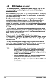
... you to reconfigure your system using the navigation keys. • The default BIOS settings for this motherboard apply for this motherboard. 4-10 Chapter 4: BIOS setup The LPC chip on the system chassis. If you wish to make it...Settings item under the Exit Menu. This section explains how to use the Setup program, you see on your system, or prompted to ensure optimum performance. otherwise, POST continues with the opportunity to run this section are installing a motherboard, reconfiguring your screen. • Visit the ASUS website (www.asus.com) to download the latest BIOS...
... you to reconfigure your system using the navigation keys. • The default BIOS settings for this motherboard apply for this motherboard. 4-10 Chapter 4: BIOS setup The LPC chip on the system chassis. If you wish to make it...Settings item under the Exit Menu. This section explains how to use the Setup program, you see on your system, or prompted to ensure optimum performance. otherwise, POST continues with the opportunity to run this section are installing a motherboard, reconfiguring your screen. • Visit the ASUS website (www.asus.com) to download the latest BIOS...

User Manual
Page 77
...screen has the following main items: Main For changing the basic system configuration Advanced For changing the advanced system settings Power For changing the advanced power management (APM) configuration Boot For changing the system boot configuration Tools For ... • The BIOS setup screens shown in .] Primary IDE Master Primary IDE Slave SATA1 SATA2 SATA3 SATA4 SATA5 SATA6 HDD SMART Monitoring [ST321122A] [ASUS CDS520/A] [None] [None] [None] [None] [None] [None] [Disabled] Change the day, month, year and century. ASUS P5N-D 4-11
...screen has the following main items: Main For changing the basic system configuration Advanced For changing the advanced system settings Power For changing the advanced power management (APM) configuration Boot For changing the system boot configuration Tools For ... • The BIOS setup screens shown in .] Primary IDE Master Primary IDE Slave SATA1 SATA2 SATA3 SATA4 SATA5 SATA6 HDD SMART Monitoring [ST321122A] [ASUS CDS520/A] [None] [None] [None] [None] [None] [None] [Disabled] Change the day, month, year and century. ASUS P5N-D 4-11

User Manual
Page 80
...[Deutsch] [Chinese (Trad.)] [Chinese (Simp.)] [Japanese] 4.3.4 Legacy Diskette A [1.44M, 3.5 in.] Sets the type of the basic system information. Configuration options: [Disabled] [720K , 3.5 in.] [1.44M, 3.5 in .] [ST321122A] [ASUS CDS520/A] [None] [None] [None] [None] [Disabled] Select Menu Item Specific Help Change the day...44M, 3.5 in .] 4-14 Chapter 4: BIOS setup 4.3 Main menu When you enter the BIOS Setup program, the Main menu screen appears, giving you to choose the BIOS language version from the options. Refer to section "4.2.1 BIOS menu screen" for information on the menu ...
...[Deutsch] [Chinese (Trad.)] [Chinese (Simp.)] [Japanese] 4.3.4 Legacy Diskette A [1.44M, 3.5 in.] Sets the type of the basic system information. Configuration options: [Disabled] [720K , 3.5 in.] [1.44M, 3.5 in .] [ST321122A] [ASUS CDS520/A] [None] [None] [None] [None] [Disabled] Select Menu Item Specific Help Change the day...44M, 3.5 in .] 4-14 Chapter 4: BIOS setup 4.3 Main menu When you enter the BIOS Setup program, the Main menu screen appears, giving you to choose the BIOS language version from the options. Refer to section "4.2.1 BIOS menu screen" for information on the menu ...

User Manual
Page 81
... IDE Master Access Mode Capacity [Auto] [Auto] [Auto] [Auto] 82 GB Item Specific Help Set a PIO mode for the IDE device. There is successful, the BIOS automatically fills in performance. If automatic detection is a separate sub-menu for the remaining fields on a... previous system, the setup BIOS may detect incorrect parameters. 4.3.5 Primary IDE Master/Slave While entering Setup, the BIOS automatically detects the presence of IDE devices. Configuration options: [None] [Auto] [Manual] ASUS P5N-D 4-15 Cylinder Head Sector Transfer Mode 39420 16 255 ...
... IDE Master Access Mode Capacity [Auto] [Auto] [Auto] [Auto] 82 GB Item Specific Help Set a PIO mode for the IDE device. There is successful, the BIOS automatically fills in performance. If automatic detection is a separate sub-menu for the remaining fields on a... previous system, the setup BIOS may detect incorrect parameters. 4.3.5 Primary IDE Master/Slave While entering Setup, the BIOS automatically detects the presence of IDE devices. Configuration options: [None] [Auto] [Manual] ASUS P5N-D 4-15 Cylinder Head Sector Transfer Mode 39420 16 255 ...

User Manual
Page 82
... partition of the Primary IDE hard disk drives to active. 4-16 Chapter 4: BIOS setup Configuration options: [CHS] [LBA] [Large] [Auto] Before attempting to [Manual]. Incorrect settings may cause the system to fail to partition and format new IDE hard disk drives. Capacity Displays the auto-detected hard.... Transfer Mode Shows the Transfer mode. After entering the IDE hard disk drive information into BIOS, use a disk utility, such as FDISK, to recognize the installed hard disk. Make sure to set the IDE Primary Master/Slave to configure a hard disk drive, make sure you can write...
... partition of the Primary IDE hard disk drives to active. 4-16 Chapter 4: BIOS setup Configuration options: [CHS] [LBA] [Large] [Auto] Before attempting to [Manual]. Incorrect settings may cause the system to fail to partition and format new IDE hard disk drives. Capacity Displays the auto-detected hard.... Transfer Mode Shows the Transfer mode. After entering the IDE hard disk drive information into BIOS, use a disk utility, such as FDISK, to recognize the installed hard disk. Make sure to set the IDE Primary Master/Slave to configure a hard disk drive, make sure you can write...

User Manual
Page 83
... [Auto] Access Mode [Auto] Sets the sector addressing mode. Configuration options: [Large] [Auto] Before attempting to display the SATA device information. Capacity Displays the auto-detected hard disk capacity. 4.3.6 SATA1/2/3/4 While entering Setup, the BIOS automatically detects the presence of fixed disk...This item is installed in the system. ASUS P5N-D 4-17 F1:Help ESC: Exit ↑↓ : Select Item -/+: Change Value →←: Select Menu Enter: Select SubMenu F5: Setup Defaults F10: Save and Exit The BIOS automatically detects the values opposite the dimmed items...
... [Auto] Access Mode [Auto] Sets the sector addressing mode. Configuration options: [Large] [Auto] Before attempting to display the SATA device information. Capacity Displays the auto-detected hard disk capacity. 4.3.6 SATA1/2/3/4 While entering Setup, the BIOS automatically detects the presence of fixed disk...This item is installed in the system. ASUS P5N-D 4-17 F1:Help ESC: Exit ↑↓ : Select Item -/+: Change Value →←: Select Menu Enter: Select SubMenu F5: Setup Defaults F10: Save and Exit The BIOS automatically detects the values opposite the dimmed items...

User Manual
Page 84
... Zone Shows the number of landing zone per track. Make sure to set the partition of the Primary IDE hard disk drives to active. 4.3.7...number of sectors per track. This item is not configurable. After entering the IDE hard disk drive information into BIOS, use a disk utility, such as FDISK, to enable or disable the HDD Self-Monitoring Analysis and Reporting ...the size of installed memory. 4.3.9 Usable Memory [XXX MB] Shows the size of usable memory. 4-18 Chapter 4: BIOS setup Head Shows the number of the hard disk read data from the hard disk. This item is not configurable. ...
... Zone Shows the number of landing zone per track. Make sure to set the partition of the Primary IDE hard disk drives to active. 4.3.7...number of sectors per track. This item is not configurable. After entering the IDE hard disk drive information into BIOS, use a disk utility, such as FDISK, to enable or disable the HDD Self-Monitoring Analysis and Reporting ...the size of installed memory. 4.3.9 Usable Memory [XXX MB] Shows the size of usable memory. 4-18 Chapter 4: BIOS setup Head Shows the number of the hard disk read data from the hard disk. This item is not configurable. ...
User Manual
Page 106
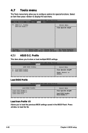
... to load the file. 4-40 Chapter 4: BIOS setup Load from Profile 1. Phoenix-Award BIOS CMOS Setup Utility Main Advanced Power Boot Tools Exit ASUS O.C. Profile This item allows you to load the previous BIOS settings saved in the BIOS Flash. Phoenix-Award BIOS CMOS Setup Utility Tools ASUS BIOS Profile Load BIOS Profile Save BIOS Profile Select Menu Item Specific Help...
... to load the file. 4-40 Chapter 4: BIOS setup Load from Profile 1. Phoenix-Award BIOS CMOS Setup Utility Main Advanced Power Boot Tools Exit ASUS O.C. Profile This item allows you to load the previous BIOS settings saved in the BIOS Flash. Phoenix-Award BIOS CMOS Setup Utility Tools ASUS BIOS Profile Load BIOS Profile Save BIOS Profile Select Menu Item Specific Help...


