
User Manual
Page 5
... HDD SMART Monitoring [Disabled 4-18 4.3.8 Installed Memory [xxx MB 4-18 4.3.9 Usable Memory [XXX MB 4-18 4.4 Advanced menu 4-19 4.4.1 JumperFree Configuration 4-19 Voltage Control 4-20 4.4.2 AI NET2 4-22 4.4.3 CPU Configuration 4-23 4.4.4 Chipset 4-24 4.4.5 PCIPnP 4-26 4.4.6 Onboard Device Configuration 4-27 4.4.7 USB Configuration 4-29 4.5 Power menu 4-30 4.5.1 ACPI Suspend Type [S1&S3 4-30 4.5.2 ACPI APIC Support [Enabled 4-30 4.5.3 APM Configuration 4-31 4.5.4 Hardware Monitor 4-33 4.6 Boot menu 4-35 4.6.1 Boot Device Priority 4-35 4.6.2 Removable Drives 4-35 4.6.3 Hard...
... HDD SMART Monitoring [Disabled 4-18 4.3.8 Installed Memory [xxx MB 4-18 4.3.9 Usable Memory [XXX MB 4-18 4.4 Advanced menu 4-19 4.4.1 JumperFree Configuration 4-19 Voltage Control 4-20 4.4.2 AI NET2 4-22 4.4.3 CPU Configuration 4-23 4.4.4 Chipset 4-24 4.4.5 PCIPnP 4-26 4.4.6 Onboard Device Configuration 4-27 4.4.7 USB Configuration 4-29 4.5 Power menu 4-30 4.5.1 ACPI Suspend Type [S1&S3 4-30 4.5.2 ACPI APIC Support [Enabled 4-30 4.5.3 APM Configuration 4-31 4.5.4 Hardware Monitor 4-33 4.6 Boot menu 4-35 4.6.1 Boot Device Priority 4-35 4.6.2 Removable Drives 4-35 4.6.3 Hard...
User Manual
Page 6
...® RAID configurations 5-30 5.5 Creating a RAID driver disk 5-37 Chapter 6: NVIDIA® SLI™ technology support 6.1 Overview 6-1 Requirements 6-1 6.2 Dual graphics card setup 6-2 6.2.1 Installing SLI-ready graphics cards 6-2 6.2.2 Installing the device drivers 6-5 6.2.3 Enabling the multi-GPU feature in Windows 6-5 Appendix: CPU features A.1 Intel® EM64T A-1 A.2 Enhanced Intel SpeedStep® Technology (EIST A-1 A.2.1 System requirements A-1 A.2.2 Using the EIST A-2 A.3 Intel® Hyper-Threading Technology A-3 vi 5.2.3 Utilities menu 5-3 5.2.4 Make disk menu...
...® RAID configurations 5-30 5.5 Creating a RAID driver disk 5-37 Chapter 6: NVIDIA® SLI™ technology support 6.1 Overview 6-1 Requirements 6-1 6.2 Dual graphics card setup 6-2 6.2.1 Installing SLI-ready graphics cards 6-2 6.2.2 Installing the device drivers 6-5 6.2.3 Enabling the multi-GPU feature in Windows 6-5 Appendix: CPU features A.1 Intel® EM64T A-1 A.2 Enhanced Intel SpeedStep® Technology (EIST A-1 A.2.1 System requirements A-1 A.2.2 Using the EIST A-2 A.3 Intel® Hyper-Threading Technology A-3 vi 5.2.3 Utilities menu 5-3 5.2.4 Make disk menu...
User Manual
Page 43
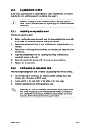
... PCI groups, making the system unstable and the card inoperable. Align the card connector with the slot and press firmly until the card is already installed in a chassis). 3. Turn on the next page for the expansion card. Refer to use . 4. Remove the system unit cover (if your motherboard is completely seated on BIOS setup. 2. Remove the bracket opposite the slot that came with the screw you removed earlier. 6. ASUS P5N...
... PCI groups, making the system unstable and the card inoperable. Align the card connector with the slot and press firmly until the card is already installed in a chassis). 3. Turn on the next page for the expansion card. Refer to use . 4. Remove the system unit cover (if your motherboard is completely seated on BIOS setup. 2. Remove the bracket opposite the slot that came with the screw you removed earlier. 6. ASUS P5N...
User Manual
Page 45
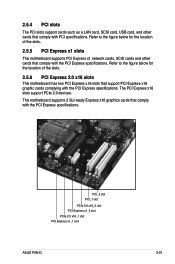
... the PCI Express specifications. Refer to the figure below for the location of the slots. 2.5.5 PCI Express x1 slots This motherboard supports PCI Express x1 network cards, SCSI cards and other cards that comply with the PCI Express specifications. PCI_2 slot PCI_1 slot PCIe 2.0 x16_2 slot PCI Express x1_2 slot PCIe 2.0 x16_1 slot PCI Express x1_1 slot ASUS P5N-D 2-21 2.5.4 PCI slots The PCI slots support cards such as a LAN card, SCSI card, USB card, and other cards that comply with the PCI Express specifications. This motherboard supports 2 SLI-ready Express x16 graphics cards...
... the PCI Express specifications. Refer to the figure below for the location of the slots. 2.5.5 PCI Express x1 slots This motherboard supports PCI Express x1 network cards, SCSI cards and other cards that comply with the PCI Express specifications. PCI_2 slot PCI_1 slot PCIe 2.0 x16_2 slot PCI Express x1_2 slot PCIe 2.0 x16_1 slot PCI Express x1_1 slot ASUS P5N-D 2-21 2.5.4 PCI slots The PCI slots support cards such as a LAN card, SCSI card, USB card, and other cards that comply with the PCI Express specifications. This motherboard supports 2 SLI-ready Express x16 graphics cards...

User Manual
Page 51
...34-1 pin FLOPPY) This connector is for the provided floppy disk drive (FDD) signal cable. P5N-D Floppy disk drive connector 2. IDE connector (40-1 pin PRI_EIDE) The onboard IDE connector is for the Ultra DMA 133/100/66 signal cable. Pin 5 on the connector is removed to prevent incorrect cable connection when using a FDD cable with a covered Pin 5. ® P5N-D FLOPPY PIN 1 NOTE: Orient the red markings on the floppy ribbon cable to PIN 1. ® P5N-D P5N-D IDE connector Drive jumper setting Single device Two devices Cable-Select or Master Cable-Select Master Slave Mode of...
...34-1 pin FLOPPY) This connector is for the provided floppy disk drive (FDD) signal cable. P5N-D Floppy disk drive connector 2. IDE connector (40-1 pin PRI_EIDE) The onboard IDE connector is for the Ultra DMA 133/100/66 signal cable. Pin 5 on the connector is removed to prevent incorrect cable connection when using a FDD cable with a covered Pin 5. ® P5N-D FLOPPY PIN 1 NOTE: Orient the red markings on the floppy ribbon cable to PIN 1. ® P5N-D P5N-D IDE connector Drive jumper setting Single device Two devices Cable-Select or Master Cable-Select Master Slave Mode of...

User Manual
Page 52
... on the Ultra DMA cable connector. If you installed Serial ATA hard disk drives, you connect the IDE cable. • Use the 80-conductor IDE cable for Serial ATA hard disk drives. If any device jumper is set to match the covered hole on the IDE connector is set as "Cable-Select," make sure all other device jumpers have the same setting. 3. These connectors support Native Command Queuing (NCQ), Power Management (PM) Implementation Algorithm, Hot Swap and smart setup. 2-28 Chapter 2: Hardware...
... on the Ultra DMA cable connector. If you installed Serial ATA hard disk drives, you connect the IDE cable. • Use the 80-conductor IDE cable for Serial ATA hard disk drives. If any device jumper is set to match the covered hole on the IDE connector is set as "Cable-Select," make sure all other device jumpers have the same setting. 3. These connectors support Native Command Queuing (NCQ), Power Management (PM) Implementation Algorithm, Hot Swap and smart setup. 2-28 Chapter 2: Hardware...
User Manual
Page 53
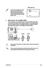
... these connectors, then install the module to a slot opening at the back of the SATA cable to the onboard SATA port to avoid mechanical conflict with USB 2.0 specification that supports up to 480 Mbps connection speed. ® P5N-D USB56 USB78 USB+5V USB_P8USB_P8+ GND NC USB+5V USB_P6USB_P6+ GND NC USB+5V USB_P7USB_P7+ GND USB+5V USB_P5USB_P5+ GND PIN1 PIN1 P5N-D USB 2.0 connectors Never connect a 1394 cable to the USB connector onboard. These USB connectors comply with huge graphics cards. ASUS P5N...
... these connectors, then install the module to a slot opening at the back of the SATA cable to the onboard SATA port to avoid mechanical conflict with USB 2.0 specification that supports up to 480 Mbps connection speed. ® P5N-D USB56 USB78 USB+5V USB_P8USB_P8+ GND NC USB+5V USB_P6USB_P6+ GND NC USB+5V USB_P7USB_P7+ GND USB+5V USB_P5USB_P5+ GND PIN1 PIN1 P5N-D USB 2.0 connectors Never connect a 1394 cable to the USB connector onboard. These USB connectors comply with huge graphics cards. ASUS P5N...
User Manual
Page 67
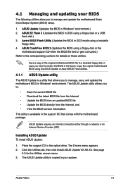
... motherboard BIOS in DOS mode using a floppy disk or a USB flash disk.) 3. ASUS Update requires an Internet connection either through a network or an Internet Service Provider (ISP). Click the Utilities tab, then click Install ASUS Update VX.XX.XX. The ASUS Update utility is a utility that comes with the motherboard package. Copy the original motherboard BIOS using a floppy disk or the motherboard support CD when the BIOS file fails or gets corrupted.) Refer to manage and update the motherboard Basic Input/Output System (BIOS) setup. 1. This utility...
... motherboard BIOS in DOS mode using a floppy disk or a USB flash disk.) 3. ASUS Update requires an Internet connection either through a network or an Internet Service Provider (ISP). Click the Utilities tab, then click Install ASUS Update VX.XX.XX. The ASUS Update utility is a utility that comes with the motherboard package. Copy the original motherboard BIOS using a floppy disk or the motherboard support CD when the BIOS file fails or gets corrupted.) Refer to manage and update the motherboard Basic Input/Output System (BIOS) setup. 1. This utility...

User Manual
Page 79
... of the menu screen is a brief description of diskette drive A. ASUS P5N-D 4-13 Main Phoenix-AwardBIOS CMOS Setup Utility Advanced Power Boot Tools Exit System Time System Date Language 15 : 30 : 36 Thu, Apr 6 2006 [English] Legacy Diskette A: [1.44M, 3.5 in.] Legacy Diskette A: Primary IDE Master [ST321122A] Primary IDE SlaveDisable[dASUS CDS5..2.0./.A][ ] SATA1 720K , [3.N5onien]. ..... [ ] SATA2 1.44M, [3.N5onien]. ..... [ ] SATA3 [None] SATA4 [None] HDD SMART Monitoring [Disabled] Select Menu Item Specific Help Specifies...
... of the menu screen is a brief description of diskette drive A. ASUS P5N-D 4-13 Main Phoenix-AwardBIOS CMOS Setup Utility Advanced Power Boot Tools Exit System Time System Date Language 15 : 30 : 36 Thu, Apr 6 2006 [English] Legacy Diskette A: [1.44M, 3.5 in.] Legacy Diskette A: Primary IDE Master [ST321122A] Primary IDE SlaveDisable[dASUS CDS5..2.0./.A][ ] SATA1 720K , [3.N5onien]. ..... [ ] SATA2 1.44M, [3.N5onien]. ..... [ ] SATA3 [None] SATA4 [None] HDD SMART Monitoring [Disabled] Select Menu Item Specific Help Specifies...

User Manual
Page 81
... increase in the system. Configuration options: [Auto] [Mode 0] [Mode 1] [Mode 2] [Mode 3] [Mode 4] UDMA Mode [Auto] Disables or sets the UDMA mode. If the hard disk was already formatted on this sub-menu. Select [Manual] to automatically detect an IDE hard disk drive. Main Phoenix-Award BIOS CMOS Setup Utility Primary IDE Master Select Menu PIO Mode UDMA Mode Primary IDE Master Access Mode Capacity [Auto] [Auto] [Auto] [Auto] 82 GB Item Specific Help Set a PIO mode for the IDE device. These items show N/A if no drive is a separate sub-menu for the remaining fields on...
... increase in the system. Configuration options: [Auto] [Mode 0] [Mode 1] [Mode 2] [Mode 3] [Mode 4] UDMA Mode [Auto] Disables or sets the UDMA mode. If the hard disk was already formatted on this sub-menu. Select [Manual] to automatically detect an IDE hard disk drive. Main Phoenix-Award BIOS CMOS Setup Utility Primary IDE Master Select Menu PIO Mode UDMA Mode Primary IDE Master Access Mode Capacity [Auto] [Auto] [Auto] [Auto] 82 GB Item Specific Help Set a PIO mode for the IDE device. These items show N/A if no drive is a separate sub-menu for the remaining fields on...

User Manual
Page 83
... type of Serial ATA devices. Capacity Displays the auto-detected hard disk capacity. This item is a separate sub-menu for each SATA device. Select a device item then press to the system. Configuration options: [None] [Auto] Access Mode [Auto] Sets the sector addressing mode. Cylinder Shows the number of fixed disk connected to display the SATA device information. Main Phoenix-Award BIOS CMOS Setup Utility SATA 1 Extended IDE Drive Access Mode [Auto] [Auto] Capacity 80 GB Cylinder 0 Head 0 Landing Zone 0 Sector 0 Select Menu Item Specific Help Selects the type...
... type of Serial ATA devices. Capacity Displays the auto-detected hard disk capacity. This item is a separate sub-menu for each SATA device. Select a device item then press to the system. Configuration options: [None] [Auto] Access Mode [Auto] Sets the sector addressing mode. Cylinder Shows the number of fixed disk connected to display the SATA device information. Main Phoenix-Award BIOS CMOS Setup Utility SATA 1 Extended IDE Drive Access Mode [Auto] [Auto] Capacity 80 GB Cylinder 0 Head 0 Landing Zone 0 Sector 0 Select Menu Item Specific Help Selects the type...

User Manual
Page 93
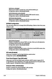
... Panel Support Type [HD Audio] Onboard nVidia LAN [Enabled] Onboard LAN Boot ROM [Disabled] �O�n�bo�a�rd��13�94 E�n�ab�l�ed�] Serial Port1 Address [3F8/IRQ4] Parallel Port Address [378/IRQ7] Parallel Port Mode [EPP] x ECP Mode Use DMA 3 Select Menu Item Specific Help Press [Enter] to enable or disable the onchip SATA1/SATA2 port. Advanced Phoenix-Award BIOS CMOS Setup Utility IDE Function Setup Select Menu OnChip IDE Channel0 OnChip IDE...
... Panel Support Type [HD Audio] Onboard nVidia LAN [Enabled] Onboard LAN Boot ROM [Disabled] �O�n�bo�a�rd��13�94 E�n�ab�l�ed�] Serial Port1 Address [3F8/IRQ4] Parallel Port Address [378/IRQ7] Parallel Port Mode [EPP] x ECP Mode Use DMA 3 Select Menu Item Specific Help Press [Enter] to enable or disable the onchip SATA1/SATA2 port. Advanced Phoenix-Award BIOS CMOS Setup Utility IDE Function Setup Select Menu OnChip IDE Channel0 OnChip IDE...
User Manual
Page 94
... options: [Disabled] [Enabled] IDE Prefetch Mode [Enabled] Allows you to [Enabled], the succeeding items become user-configurable. RAID Enabled [Disabled] Enables or disables the onboard RAID controller. Configuration options: [AC97] [HD Audio] Onboard nVidia LAN [Enabled] Enables or disables the onboard NVIDIA® LAN controller. When set the front panel audio connector (AAFP) mode to edit. Configuration options: [Disabled] [Enabled] 4-28 Chapter 4: BIOS setup SATA Port 3, 4 [Enabled] Allows you to change Serial ATA settings. Configuration options: [Disabled] [Enabled...
... options: [Disabled] [Enabled] IDE Prefetch Mode [Enabled] Allows you to [Enabled], the succeeding items become user-configurable. RAID Enabled [Disabled] Enables or disables the onboard RAID controller. Configuration options: [AC97] [HD Audio] Onboard nVidia LAN [Enabled] Enables or disables the onboard NVIDIA® LAN controller. When set the front panel audio connector (AAFP) mode to edit. Configuration options: [Disabled] [Enabled] 4-28 Chapter 4: BIOS setup SATA Port 3, 4 [Enabled] Allows you to change Serial ATA settings. Configuration options: [Disabled] [Enabled...

User Manual
Page 96
... Menu -/+: Change Value Enter: Select SubMenu F5: Setup Defaults F10: Save and Exit 4.5.1 ACPI Suspend Type [S1&S3] Allows you to select the Advanced Configuration and Power Interface (ACPI) state to be used for System Suspend. When set to enable or disable the Advanced Configuration and Power Interface (ACPI) support in the RSDT pointer list. Phoenix-AwardBIOS CMOS Setup Utility Main Advanced Power Boot Tools Exit ACPI Suspend Type ACPI APIC support APM Configuration Hardware Monitor [S1&S3] Enabled Select Menu Item Specific Help...
... Menu -/+: Change Value Enter: Select SubMenu F5: Setup Defaults F10: Save and Exit 4.5.1 ACPI Suspend Type [S1&S3] Allows you to select the Advanced Configuration and Power Interface (ACPI) state to be used for System Suspend. When set to enable or disable the Advanced Configuration and Power Interface (ACPI) support in the RSDT pointer list. Phoenix-AwardBIOS CMOS Setup Utility Main Advanced Power Boot Tools Exit ACPI Suspend Type ACPI APIC support APM Configuration Hardware Monitor [S1&S3] Enabled Select Menu Item Specific Help...

User Manual
Page 99
...;] ASUS P5N-D 4-33 CPU Q-Fan Profile [Performance] Allows you to enable or disable the CPU Q-Fan controller. 4.5.4 Hardware Monitor The items in this item to [Silent Mode] to minimize fan speed for quiet CPU fan operation, or [Performance Mode] to achieve maximum CPU fan speed. Configuration options: [Disabled] [Enabled] The Chassis Q-Fan Profile item becomes user-configurable when you to enable or disable the Chassis Q-fan. Phoenix-Award BIOS CMOS Setup Utility Power Hardware Monitor Select Menu CPU Q-Fan Control [Disabled] x CPU Q-Fan Profile Performance Chassis Q-Fan Control...
...;] ASUS P5N-D 4-33 CPU Q-Fan Profile [Performance] Allows you to enable or disable the CPU Q-Fan controller. 4.5.4 Hardware Monitor The items in this item to [Silent Mode] to minimize fan speed for quiet CPU fan operation, or [Performance Mode] to achieve maximum CPU fan speed. Configuration options: [Disabled] [Enabled] The Chassis Q-Fan Profile item becomes user-configurable when you to enable or disable the Chassis Q-fan. Phoenix-Award BIOS CMOS Setup Utility Power Hardware Monitor Select Menu CPU Q-Fan Control [Disabled] x CPU Q-Fan Profile Performance Chassis Q-Fan Control...

User Manual
Page 101
... the screen depends on the number of devices installed in the system. ASUS P5N-D 4-35 Select an item then press to display the sub-menu. Configuration options: [Removable] [Hard Disk] [CDROM] [Disabled] 4.6.2 Removable Drives Phoenix-Award BIOS CMOS Setup Utility Boot Removable Drives 1. Floppy Disks Allows you to change the system boot options. Phoenix-Award BIOS CMOS Setup Utility Main Advanced Power Boot Tools Exit Boot Device Priority Removable Drives Hard Disk Drives CDROM Drives Boot Settings Configuration Security Select Menu Item Specific Help Select Boot Device Priority...
... the screen depends on the number of devices installed in the system. ASUS P5N-D 4-35 Select an item then press to display the sub-menu. Configuration options: [Removable] [Hard Disk] [CDROM] [Disabled] 4.6.2 Removable Drives Phoenix-Award BIOS CMOS Setup Utility Boot Removable Drives 1. Floppy Disks Allows you to change the system boot options. Phoenix-Award BIOS CMOS Setup Utility Main Advanced Power Boot Tools Exit Boot Device Priority Removable Drives Hard Disk Drives CDROM Drives Boot Settings Configuration Security Select Menu Item Specific Help Select Boot Device Priority...

User Manual
Page 109
... not want to save your changes to the BIOS items. Phoenix-AwardBIOS CMOS Setup Utility Main Advanced Power Boot Tools Exit Exit & Save Changes Exit & Discard Changes Load Setup Default Discard Changes Select Menu Item Specific Help This option save data to CMOS and exiting the setup menu. Select YES to load default values. ASUS P5N-D 4-43 Exit & Save Changes Once you are saved to the CMOS RAM. An onboard backup battery sustains the CMOS RAM so it stays on the...
... not want to save your changes to the BIOS items. Phoenix-AwardBIOS CMOS Setup Utility Main Advanced Power Boot Tools Exit Exit & Save Changes Exit & Discard Changes Load Setup Default Discard Changes Select Menu Item Specific Help This option save data to CMOS and exiting the setup menu. Select YES to load default values. ASUS P5N-D 4-43 Exit & Save Changes Once you are saved to the CMOS RAM. An onboard backup battery sustains the CMOS RAM so it stays on the...

User Manual
Page 142
... installing the hard disk drives, make sure to set the BIOS RAID items: 1. To set the necessary RAID items in the BIOS. Refer to section "5.5 Creating a RAID driver disk" for detailed information on each drive. Connect a SATA power cable to the power connector on RAID configurations. See section "4.4.6 Onboard Device Configuration > NVRAID Configuration" for four independent Serial ATA channels. Select and enable the SATA drive(s) that you want to boot the system from the Support CD to a floppy disk before setting your changes and Exit Setup. 5-30 Chapter 5: Software support...
... installing the hard disk drives, make sure to set the BIOS RAID items: 1. To set the necessary RAID items in the BIOS. Refer to section "5.5 Creating a RAID driver disk" for detailed information on each drive. Connect a SATA power cable to the power connector on RAID configurations. See section "4.4.6 Onboard Device Configuration > NVRAID Configuration" for four independent Serial ATA channels. Select and enable the SATA drive(s) that you want to boot the system from the Support CD to a floppy disk before setting your changes and Exit Setup. 5-30 Chapter 5: Software support...
User Manual
Page 149
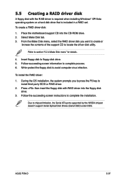
... driver. 2. Press then insert the floppy disk with the RAID driver is required when installing Windows® XP/Vista operating system on a hard disk drive that is included in a RAID set. Follow the succeeding screen instructions to floppy disk drive. 5. ASUS P5N-D 5-37 Insert floppy disk to complete the installation. Write-protect the floppy disk to chipset limitation, the Serial ATA ports supported by the NVIDIA chipset doesn't support Serial Optical Disk Drives (Serial ODD) under DOS. Place the motherboard support CD into the floppy disk drive. 3. To install the RAID driver...
... driver. 2. Press then insert the floppy disk with the RAID driver is required when installing Windows® XP/Vista operating system on a hard disk drive that is included in a RAID set. Follow the succeeding screen instructions to floppy disk drive. 5. ASUS P5N-D 5-37 Insert floppy disk to complete the installation. Write-protect the floppy disk to chipset limitation, the Serial ATA ports supported by the NVIDIA chipset doesn't support Serial Optical Disk Drives (Serial ODD) under DOS. Place the motherboard support CD into the floppy disk drive. 3. To install the RAID driver...
User Manual
Page 157
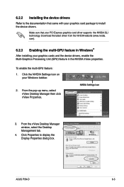
.... ASUS P5N-D 6-5 com). 6.2.3 Enabling the multi-GPU feature in the NVIDIA nView properties. NVIDIA Settings icon 3. Make sure that came with your PCI Express graphics card driver supports the NVIDIA SLI technology. Click Properties to install the device drivers. Download the latest driver from the NVIDIA website (www.nvidia. From the nView Desktop Manager window, select the Desktop Management tab. 4. 6.2.2 Installing the device drivers Refer to the documentation that your graphics card package to display the Display...
.... ASUS P5N-D 6-5 com). 6.2.3 Enabling the multi-GPU feature in the NVIDIA nView properties. NVIDIA Settings icon 3. Make sure that came with your PCI Express graphics card driver supports the NVIDIA SLI technology. Click Properties to install the device drivers. Download the latest driver from the NVIDIA website (www.nvidia. From the nView Desktop Manager window, select the Desktop Management tab. 4. 6.2.2 Installing the device drivers Refer to the documentation that your graphics card package to display the Display...


