User Manual
Page 25
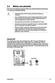
... cause severe damage to the motherboard, peripherals, and/or components. Onboard LED The motherboard comes with the component. • Before you install or remove any component, ensure that the ATX power supply is switched off ... of the following precautions before you install motherboard components or change any motherboard settings. • Unplug the power cord from the power supply. The green LED lights up to indicate that you should shut down... you proceed Take note of the onboard LED. ® P5N-D P5N-D Onboard LED SB_PWR ON Standby Power OFF Powered Off ASUS P5N-D 2-1
... cause severe damage to the motherboard, peripherals, and/or components. Onboard LED The motherboard comes with the component. • Before you install or remove any component, ensure that the ATX power supply is switched off ... of the following precautions before you install motherboard components or change any motherboard settings. • Unplug the power cord from the power supply. The green LED lights up to indicate that you should shut down... you proceed Take note of the onboard LED. ® P5N-D P5N-D Onboard LED SB_PWR ON Standby Power OFF Powered Off ASUS P5N-D 2-1

User Manual
Page 28
...25 2-25 2-25 2-25 2-25 2-25 2-25 2-26 2-26 2-26 2-26 2-26 2-26 2-26 2-26 2-4 Chapter 2: Hardware information Line In port (light blue) 8. Optical S/PDIF Out port 15. 2.2.4 Slots 1. 2. 3. 4. Coaxial S/PDIF Out port 16. Microphone port (pink) 10. Clear RTC RAM (3-pin ...CLRTC) 2. Parellel port 3. USB device wake-up (3-pin USBPW1-4, USBPW5-8) 3. PS/2 mouse port (green) 2. Rear Speaker Out port (black) 7. Keyboard power (3-pin KBPWR) Rear panel connectors 1. Layout contents DDR2 DIMM slots PCI slot PCI Express x...
...25 2-25 2-25 2-25 2-25 2-25 2-25 2-26 2-26 2-26 2-26 2-26 2-26 2-26 2-26 2-4 Chapter 2: Hardware information Line In port (light blue) 8. Optical S/PDIF Out port 15. 2.2.4 Slots 1. 2. 3. 4. Coaxial S/PDIF Out port 16. Microphone port (pink) 10. Clear RTC RAM (3-pin ...CLRTC) 2. Parellel port 3. USB device wake-up (3-pin USBPW1-4, USBPW5-8) 3. PS/2 mouse port (green) 2. Rear Speaker Out port (black) 7. Keyboard power (3-pin KBPWR) Rear panel connectors 1. Layout contents DDR2 DIMM slots PCI slot PCI Express x...

User Manual
Page 49
...Mbps connection ORANGE 100 Mbps connection GREEN 1 Gbps connection LAN port 5. Center/Subwoofer port (orange). This port connects a headphone or a speaker. Line Out port (lime). ASUS P5N-D 2-25 Refer to a Local Area Network (LAN) through a network hub. Line In port (light blue). Parallel port. This 25... Speaker Out port (black). This port connects the tape, CD, DVD player, or other devices. 3. PS/2 mouse port (green). This port is for a PS/2 mouse. 2. In 4-channel, 6-channel, and 8-channel configuration, the function of this port becomes Front Speaker Out.
...Mbps connection ORANGE 100 Mbps connection GREEN 1 Gbps connection LAN port 5. Center/Subwoofer port (orange). This port connects a headphone or a speaker. Line Out port (lime). ASUS P5N-D 2-25 Refer to a Local Area Network (LAN) through a network hub. Line In port (light blue). Parallel port. This 25... Speaker Out port (black). This port connects the tape, CD, DVD player, or other devices. 3. PS/2 mouse port (green). This port is for a PS/2 mouse. 2. In 4-channel, 6-channel, and 8-channel configuration, the function of this port becomes Front Speaker Out.

User Manual
Page 63
...on the system front panel case lights up. ASUS�P�5�N��-D� 3-1 External SCSI devices (starting with ATX power supplies, the system LED lights up when you turned on the power, the system may light up or switch between orange and green after the system LED turns on... up for assistance. 7. After making all switches are running, the BIOS beeps (see anything within 30 seconds from the time you press the ATX power button. Turn on the screen. Connect the power cord to enter the BIOS Setup. System power 6. While the tests are off. 3....
...on the system front panel case lights up. ASUS�P�5�N��-D� 3-1 External SCSI devices (starting with ATX power supplies, the system LED lights up when you turned on the power, the system may light up or switch between orange and green after the system LED turns on... up for assistance. 7. After making all switches are running, the BIOS beeps (see anything within 30 seconds from the time you press the ATX power button. Turn on the screen. Connect the power cord to enter the BIOS Setup. System power 6. While the tests are off. 3....


