
User Manual
Page 31
BIOS 2.1 使用 AFUDOS BIOS AFUDOS DOS BIOS BIOS 程式。AFUDOS BIOS BIOS BIOS 程式 BIOS 程式。 1.2MB BIOS 1 AFUDOS 程式(afudos. Version 1.19(ASUS V2.07(03.11.24BB)) Copyright (C) 2002 American Megatrends, Inc. done Write to file...... Reading flash ..... exe 2 DOS afudos /o[filename filename A:\>afudos /oOLDBIOS1.rom 3. 按下 afudos /oOLDBIOS1.rom AMI Firmware Update Utility - All rights reserved. ok A:\> 當 BIOS DOS 31
BIOS 2.1 使用 AFUDOS BIOS AFUDOS DOS BIOS BIOS 程式。AFUDOS BIOS BIOS BIOS 程式 BIOS 程式。 1.2MB BIOS 1 AFUDOS 程式(afudos. Version 1.19(ASUS V2.07(03.11.24BB)) Copyright (C) 2002 American Megatrends, Inc. done Write to file...... Reading flash ..... exe 2 DOS afudos /o[filename filename A:\>afudos /oOLDBIOS1.rom 3. 按下 afudos /oOLDBIOS1.rom AMI Firmware Update Utility - All rights reserved. ok A:\> 當 BIOS DOS 31

User Manual
Page 32
... not turn off power during flash BIOS Reading file ....... WARNING!! Erasing flash ...... Version 1.19(ASUS V2.07(03.11.24BB)) Copyright (C) 2002 American Megatrends, Inc. WARNING!! 更新 BIOS 程式 AFUDOS BIOS 程式。 1 tw.asus.com BIOS 片中。 BIOS BIOS 2. 將 AFUDOS.EXE BIOS 3 DOS afudos /i[filename filename BIOS 程式。 A:\>afudos /iP5B-VM...
... not turn off power during flash BIOS Reading file ....... WARNING!! Erasing flash ...... Version 1.19(ASUS V2.07(03.11.24BB)) Copyright (C) 2002 American Megatrends, Inc. WARNING!! 更新 BIOS 程式 AFUDOS BIOS 程式。 1 tw.asus.com BIOS 片中。 BIOS BIOS 2. 將 AFUDOS.EXE BIOS 3 DOS afudos /i[filename filename BIOS 程式。 A:\>afudos /iP5B-VM...

User Manual
Page 33
... 程式(AWDFLASH.EXE BIOS AwardBIOS Flash BIOS 程式。 1 http://tw.asus.com BIOS M2N-VM HDMI.bin FAT 32/16 格式的 USB BIOS 2 CD/DVD AwardBIOS Flash BIOS 3 DOS 4. 當 A BIOS 檔案與 AwardBIOS Flash 5 A awdflash 並按下 鍵。 AwardBIOS Flash Utility for ASUS V1.14 (C) Phoenix Technologies Ltd...
... 程式(AWDFLASH.EXE BIOS AwardBIOS Flash BIOS 程式。 1 http://tw.asus.com BIOS M2N-VM HDMI.bin FAT 32/16 格式的 USB BIOS 2 CD/DVD AwardBIOS Flash BIOS 3 DOS 4. 當 A BIOS 檔案與 AwardBIOS Flash 5 A awdflash 並按下 鍵。 AwardBIOS Flash Utility for ASUS V1.14 (C) Phoenix Technologies Ltd...

User Manual
Page 34
...HDMI-00 DATE:04/13/2006 Flash Type - 7 BIOS N BIOS 8 BIOS BIOS AwardBIOS Flash Utility for ASUS V1.14 (C) Phoenix Technologies Ltd. PMC Pm49FL004T LPC/FWH File Name to Continue Write OK F1 Reset No Update Write Fail 34 BIOS OFE00 OK Write OK No Update Write Fail Warning: Don...'t Turn Off Power Or Reset System! 在更新 BIOS 9 Flash Complete BIOS F1 AwardBIOS Flash Utility for ASUS V1.14 (C) Phoenix Technologies Ltd. PMC Pm49FL004T LPC/FWH File Name to Program: M2A-VM HDMI.bin Flashing ...
...HDMI-00 DATE:04/13/2006 Flash Type - 7 BIOS N BIOS 8 BIOS BIOS AwardBIOS Flash Utility for ASUS V1.14 (C) Phoenix Technologies Ltd. PMC Pm49FL004T LPC/FWH File Name to Continue Write OK F1 Reset No Update Write Fail 34 BIOS OFE00 OK Write OK No Update Write Fail Warning: Don...'t Turn Off Power Or Reset System! 在更新 BIOS 9 Flash Complete BIOS F1 AwardBIOS Flash Utility for ASUS V1.14 (C) Phoenix Technologies Ltd. PMC Pm49FL004T LPC/FWH File Name to Program: M2A-VM HDMI.bin Flashing ...
User Manual
Page 4
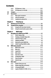
... 3-2 3.2.1 Using the OS shut down function 3-2 3.2.2 Using the dual function power switch 3-2 Chapter 4: BIOS setup 4.1 Managing and updating your BIOS 4-1 4.1.1 ASUS Update utility 4-1 4.1.2 Creating a bootable floppy disk 4-4 4.1.3 ASUS EZ Flash 2 utility 4-5 4.1.4 Updating the BIOS 4-6 4.1.5 Saving the current BIOS file 4-8 4.1.6 ASUS CrashFree BIOS 2 utility 4-9 4.2 BIOS setup program 4-10 4.2.1 BIOS menu screen 4-11 4.2.2 Menu bar 4-11 4.2.3 Legend bar 4-12 4.2.4 Menu items 4-12...
... 3-2 3.2.1 Using the OS shut down function 3-2 3.2.2 Using the dual function power switch 3-2 Chapter 4: BIOS setup 4.1 Managing and updating your BIOS 4-1 4.1.1 ASUS Update utility 4-1 4.1.2 Creating a bootable floppy disk 4-4 4.1.3 ASUS EZ Flash 2 utility 4-5 4.1.4 Updating the BIOS 4-6 4.1.5 Saving the current BIOS file 4-8 4.1.6 ASUS CrashFree BIOS 2 utility 4-9 4.2 BIOS setup program 4-10 4.2.1 BIOS menu screen 4-11 4.2.2 Menu bar 4-11 4.2.3 Legend bar 4-12 4.2.4 Menu items 4-12...
User Manual
Page 9
... to change system settings through the BIOS Setup menus. These documents are also provided. • Chapter 5: Software support This chapter describes the contents of the standard package. ix ASUS websites The ASUS website provides updated information on the motherboard. • Chapter 3: Powering up... This chapter describes the power up sequence and ways of shutting down the system. • Chapter 4: BIOS setup This chapter tells how to the...
... to change system settings through the BIOS Setup menus. These documents are also provided. • Chapter 5: Software support This chapter describes the contents of the standard package. ix ASUS websites The ASUS website provides updated information on the motherboard. • Chapter 3: Powering up... This chapter describes the power up sequence and ways of shutting down the system. • Chapter 4: BIOS setup This chapter tells how to the...
User Manual
Page 12
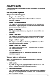
ASUS AI Direct Link ASUS Quiet Thermal Solution: - ASUS Q-Fan 2 - ASUS CrashFree BIOS 2 - ASUS AI Overclocking Precision Tweaker 2: - vCore: Adjustable CPU voltage at 1MHz increment Overclocking Protection: - vDIMM: 64-step DRAM voltage control - ASUS O.C. P5N-D�s�p��e�c�if�ic�a��ti�o�n�s��s�u�m��m�a�...
ASUS AI Direct Link ASUS Quiet Thermal Solution: - ASUS Q-Fan 2 - ASUS CrashFree BIOS 2 - ASUS AI Overclocking Precision Tweaker 2: - vCore: Adjustable CPU voltage at 1MHz increment Overclocking Protection: - vDIMM: 64-step DRAM voltage control - ASUS O.C. P5N-D�s�p��e�c�if�ic�a��ti�o�n�s��s�u�m��m�a�...

User Manual
Page 13
xiii P5N-D�s�p��e�c�if�ic�a��ti�o�n�s��s�u�m��m�a��ry� Rear panel Internal connectors BIOS features Manageability Support CD contents Form factor 1 x PS/2 ...S/PDIF Out Header Chassis Intrusion connector CD audio in 24-pin ATX Power connector 4-pin ATX 12V Power connector System Panel (Q-Connector) 8 Mb Flash ROM, AWARD BIOS, PnP, DMI2.0, WfM2.0, SM BIOS 2.4, ASUS EZ Flash 2, ASUS CrashFree BIOS 2 WfM 2.0, DMI 2.0 , WOR by Ring , WOL/...
xiii P5N-D�s�p��e�c�if�ic�a��ti�o�n�s��s�u�m��m�a��ry� Rear panel Internal connectors BIOS features Manageability Support CD contents Form factor 1 x PS/2 ...S/PDIF Out Header Chassis Intrusion connector CD audio in 24-pin ATX Power connector 4-pin ATX 12V Power connector System Panel (Q-Connector) 8 Mb Flash ROM, AWARD BIOS, PnP, DMI2.0, WfM2.0, SM BIOS 2.4, ASUS EZ Flash 2, ASUS CrashFree BIOS 2 WfM 2.0, DMI 2.0 , WOR by Ring , WOL/...
User Manual
Page 21
... up your motherboard against static electricity damage and shields it becomes easy to restore the original BIOS data from the support CD when the BIOS codes and data are corrupted. ASUS CrashFree BIOS 2 This feature allows you to easily connect or disconnect the chassis front panel cables to 70% of the total time taken. ASUS P5N-D 1-5 See...
... up your motherboard against static electricity damage and shields it becomes easy to restore the original BIOS data from the support CD when the BIOS codes and data are corrupted. ASUS CrashFree BIOS 2 This feature allows you to easily connect or disconnect the chassis front panel cables to 70% of the total time taken. ASUS P5N-D 1-5 See...
User Manual
Page 22
...the language of the motherboard BIOS allows automatic re-setting to the BIOS default settings in 0.02v steps to finetune voltages to overclocking. Update your system with customizable boot logos. See pages 4-5 and 4-42 for details. ASUS Multi-language BIOS The multi-language BIOS allows you to ...launch the utility and update the BIOS without preparing a bootable diskette or using an OS-based flash utility. eliminates the need to...
...the language of the motherboard BIOS allows automatic re-setting to the BIOS default settings in 0.02v steps to finetune voltages to overclocking. Update your system with customizable boot logos. See pages 4-5 and 4-42 for details. ASUS Multi-language BIOS The multi-language BIOS allows you to ...launch the utility and update the BIOS without preparing a bootable diskette or using an OS-based flash utility. eliminates the need to...
User Manual
Page 27
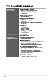
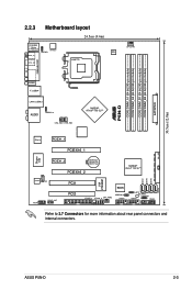
® P5N-D DDR2 DIMM_A1 (64 bit,240-pin module) DDR2 DIMM_A2 (64 bit,240-pin module) DDR2 DIMM_B1 (64 bit,240-pin module) DDR2 DIMM_B2 (64 bit,240-pin module) EATXPWR 30.5cm (12.0in) 2.2.3 Motherboard layout 24.5cm (9.6in) PS/2KBMS T: Mouse B: Keyboard SPDIF_O1 ATX12V KBPWR ...Super I/O PCIEX1_2 CR2032 3V Lithium Cell CMOS Power PCIEX16_2 NVIDIA® nForce® 750i SLI™ ALC883 CD AAFP SPDIF_OUT PCI1 PCI2 BIOS FLOPPY IE1394_2 CHA_FAN2 USBPW5-8 USB56 CLRTC SB_PWR CHASSIS USB78 PANEL VIA VT6308P SATA1 SATA2 SATA3 SATA4 Refer to 2.7 Connectors for more information ...
® P5N-D DDR2 DIMM_A1 (64 bit,240-pin module) DDR2 DIMM_A2 (64 bit,240-pin module) DDR2 DIMM_B1 (64 bit,240-pin module) DDR2 DIMM_B2 (64 bit,240-pin module) EATXPWR 30.5cm (12.0in) 2.2.3 Motherboard layout 24.5cm (9.6in) PS/2KBMS T: Mouse B: Keyboard SPDIF_O1 ATX12V KBPWR ...Super I/O PCIEX1_2 CR2032 3V Lithium Cell CMOS Power PCIEX16_2 NVIDIA® nForce® 750i SLI™ ALC883 CD AAFP SPDIF_OUT PCI1 PCI2 BIOS FLOPPY IE1394_2 CHA_FAN2 USBPW5-8 USB56 CLRTC SB_PWR CHASSIS USB78 PANEL VIA VT6308P SATA1 SATA2 SATA3 SATA4 Refer to 2.7 Connectors for more information ...
User Manual
Page 43
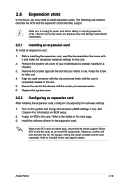
...you may cause you intend to the table on the next page for the card. 2. Remove the system unit cover (if your motherboard is completely seated on the slot. 5. Replace the system cover. 2.5.2 Configuring an expansion card After installing the expansion card, configure...card inoperable. Secure the card to the tables on BIOS setup. 2. Before installing the expansion card, read the documentation that you physical injury and damage motherboard components. 2.5.1 Installing an expansion card To install an expansion card: 1. ASUS P5N-D 2-19 Align the card connector with it by...
...you may cause you intend to the table on the next page for the card. 2. Remove the system unit cover (if your motherboard is completely seated on the slot. 5. Replace the system cover. 2.5.2 Configuring an expansion card After installing the expansion card, configure...card inoperable. Secure the card to the tables on BIOS setup. 2. Before installing the expansion card, read the documentation that you physical injury and damage motherboard components. 2.5.1 Installing an expansion card To install an expansion card: 1. ASUS P5N-D 2-19 Align the card connector with it by...
User Manual
Page 47
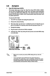
...CMOS memory of date, time, and system setup parameters by erasing the CMOS RTC RAM data. ASUS P5N-D 2-23 Shut down the key during the boot process and enter BIOS setup to re-enter data. ® P5N-D P5N-D Clear RTC RAM CLRTC 12 23 Normal Clear RTC (Default) • Make sure to ...re-enter your previous BIOS settings after you to pins 1-2. 4. 2.6 Jumpers 1. Plug the power cord and turn ON the...
...CMOS memory of date, time, and system setup parameters by erasing the CMOS RTC RAM data. ASUS P5N-D 2-23 Shut down the key during the boot process and enter BIOS setup to re-enter data. ® P5N-D P5N-D Clear RTC RAM CLRTC 12 23 Normal Clear RTC (Default) • Make sure to ...re-enter your previous BIOS settings after you to pins 1-2. 4. 2.6 Jumpers 1. Plug the power cord and turn ON the...

User Manual
Page 48
...in low power mode) using the connected USB devices. Set this jumper to pins 2-3 (+5VSB) to additional USB ports. This feature requires an ATX power supply that can provide 500mA on the +5VSB lead, and a corresponding setting in sleep mode. 3. otherwise, the system will not power ...; The total current consumed must NOT exceed the power supply capability (+5VSB) whether under normal condition or in the BIOS. USBPW1-4 2 1 +5V (Default) 3 2 +5VSB ® P5N-D USBPW5-8 12 23 +5V P5N-D USB device wake up (Default) +5VSB • The USB device wake-up the computer from S3 and S4...
...in low power mode) using the connected USB devices. Set this jumper to pins 2-3 (+5VSB) to additional USB ports. This feature requires an ATX power supply that can provide 500mA on the +5VSB lead, and a corresponding setting in sleep mode. 3. otherwise, the system will not power ...; The total current consumed must NOT exceed the power supply capability (+5VSB) whether under normal condition or in the BIOS. USBPW1-4 2 1 +5V (Default) 3 2 +5VSB ® P5N-D USBPW5-8 12 23 +5V P5N-D USB device wake up (Default) +5VSB • The USB device wake-up the computer from S3 and S4...

User Manual
Page 52
...65533;n�b��o�a�r�d�N��V�I�D��IA�® MediaShield™ RAID controller. ® P5N-D P5N-D SATA connectors SATA1 SATA2 SATA3 SATA4 GND RSATA_TXP1 RSATA_TXN1 GND RSATA_RXP1 RSATA_RXN1 GND GND RSATA_TXP2 RSATA_TXN2 GND RSATA_RXP2 RSATA_RXN2 GND GND RSATA_TXP3 RSATA_TXN3 ... connector is set using these connectors, enable the RAID Enabled item under the Serial ATA Configuration sub-menu in the BIOS. If any device jumper is removed to match the covered hole on the Ultra DMA cable connector.
...65533;n�b��o�a�r�d�N��V�I�D��IA�® MediaShield™ RAID controller. ® P5N-D P5N-D SATA connectors SATA1 SATA2 SATA3 SATA4 GND RSATA_TXP1 RSATA_TXN1 GND RSATA_RXP1 RSATA_RXN1 GND GND RSATA_TXP2 RSATA_TXN2 GND RSATA_RXP2 RSATA_RXN2 GND GND RSATA_TXP3 RSATA_TXN3 ... connector is set using these connectors, enable the RAID Enabled item under the Serial ATA Configuration sub-menu in the BIOS. If any device jumper is removed to match the covered hole on the Ultra DMA cable connector.
User Manual
Page 57
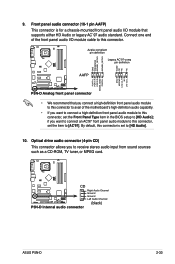
...Channel P5N-D Internal audio connector (black) ASUS P5N-D 2-33 Front panel audio connector (10-1 pin AAFP) This connector is set to [HD Audio]; By default, this connector is for a chassis-mounted front panel audio I /O module cable to this connector, set the Front Panel Type item in the BIOS setup ... panel audio module to this connector to avail of the motherboard's high-definition audio capability. • If you want to connect an AC'97 front panel audio module to [AC'97]. GND PRESENCE# SENSE1_RETUR SENSE2_RETUR ® P5N-D AGND NC NC NC MIC2 MICPWR Line out_R NC Line...
...Channel P5N-D Internal audio connector (black) ASUS P5N-D 2-33 Front panel audio connector (10-1 pin AAFP) This connector is set to [HD Audio]; By default, this connector is for a chassis-mounted front panel audio I /O module cable to this connector, set the Front Panel Type item in the BIOS setup ... panel audio module to this connector to avail of the motherboard's high-definition audio capability. • If you want to connect an AC'97 front panel audio module to [AC'97]. GND PRESENCE# SENSE1_RETUR SENSE2_RETUR ® P5N-D AGND NC NC NC MIC2 MICPWR Line out_R NC Line...

User Manual
Page 58
... Activity LED. The system power LED lights up or flashes when data is read from or written to hear system beeps and warnings. • ATX power button/soft-off mode depending on or puts the system in sleep mode. • Hard disk drive activity LED (2-pin IDE_LED) This 2-... button for the system power LED. PLED SPEAKER PANEL IDE_LED RESET PWRSW * Requires an ATX power supply. Pressing the power button turns the system on the BIOS settings. PLED+ PLED+5V Ground Ground Speaker ® P5N-D IDE_LED+ IDE_LED- Pressing the power switch for more than four seconds while the system ...
... Activity LED. The system power LED lights up or flashes when data is read from or written to hear system beeps and warnings. • ATX power button/soft-off mode depending on or puts the system in sleep mode. • Hard disk drive activity LED (2-pin IDE_LED) This 2-... button for the system power LED. PLED SPEAKER PANEL IDE_LED RESET PWRSW * Requires an ATX power supply. Pressing the power button turns the system on the BIOS settings. PLED+ PLED+5V Ground Ground Speaker ® P5N-D IDE_LED+ IDE_LED- Pressing the power switch for more than four seconds while the system ...

User Manual
Page 63
...device on . Follow the instructions in the following order: a. After making all switches are running, the BIOS beeps (see anything within 30 seconds from the time you press the ATX power button. Turn on the screen. If your retailer for the first time 1. While the tests are ...off. 3. Monitor b. System power 6. ASUS�P�5�N��-D� 3-1 3.1 Starting up for assistance. 7. Be sure...
...device on . Follow the instructions in the following order: a. After making all switches are running, the BIOS beeps (see anything within 30 seconds from the time you press the ATX power button. Turn on the screen. If your retailer for the first time 1. While the tests are ...off. 3. Monitor b. System power 6. ASUS�P�5�N��-D� 3-1 3.1 Starting up for assistance. 7. Be sure...

User Manual
Page 64
... While the system is ON, pressing the power switch for less than four seconds lets the system enter the soft-off mode regardless of the BIOS setting. The power supply should turn off after Windows® shuts down . Pressing the power switch for details. 3-2 Chapter 3: Powering up 3.2 Turning ...Using the OS shut down function If you are using Windows® Vista: 1. Click the Turn Off button to soft-off mode, depending on the BIOS setting. Click the Start button then select Turn Off Computer. 2. Refer to section 4.5 Power Menu in Chapter 4 for more than four seconds puts ...
... While the system is ON, pressing the power switch for less than four seconds lets the system enter the soft-off mode regardless of the BIOS setting. The power supply should turn off after Windows® shuts down . Pressing the power switch for details. 3-2 Chapter 3: Powering up 3.2 Turning ...Using the OS shut down function If you are using Windows® Vista: 1. Click the Turn Off button to soft-off mode, depending on the BIOS setting. Click the Start button then select Turn Off Computer. 2. Refer to section 4.5 Power Menu in Chapter 4 for more than four seconds puts ...

User Manual
Page 65
Detailed descriptions of the BIOS parameters are also provided. Chapter 4: 4 BIOS setup This chapter tells how to change the system settings through the BIOS Setup menus.
Detailed descriptions of the BIOS parameters are also provided. Chapter 4: 4 BIOS setup This chapter tells how to change the system settings through the BIOS Setup menus.


