User Manual
Page 4
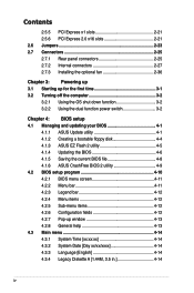
...Express x1 slots 2-21 2.5.6 PCI Express 2.0 x16 slots 2-21 2.6 Jumpers 2-23 2.7 Connectors 2-25 2.7.1 Rear panel connectors 2-25 2.7.2 Internal connectors 2-27 2.7.3 Installing the optional fan 2-36 Chapter 3: Powering up 3.1 Starting up... power switch 3-2 Chapter 4: BIOS setup 4.1 Managing and updating your BIOS 4-1 4.1.1 ASUS Update utility 4-1 4.1.2 Creating a bootable floppy disk 4-4 4.1.3 ASUS EZ Flash 2 utility 4-5 4.1.4 Updating the BIOS 4-6 4.1.5 Saving the current BIOS file 4-8 4.1.6 ASUS CrashFree BIOS 2 utility 4-9 4.2 BIOS setup program 4-10 4.2.1 BIOS menu screen 4-...
...Express x1 slots 2-21 2.5.6 PCI Express 2.0 x16 slots 2-21 2.6 Jumpers 2-23 2.7 Connectors 2-25 2.7.1 Rear panel connectors 2-25 2.7.2 Internal connectors 2-27 2.7.3 Installing the optional fan 2-36 Chapter 3: Powering up 3.1 Starting up... power switch 3-2 Chapter 4: BIOS setup 4.1 Managing and updating your BIOS 4-1 4.1.1 ASUS Update utility 4-1 4.1.2 Creating a bootable floppy disk 4-4 4.1.3 ASUS EZ Flash 2 utility 4-5 4.1.4 Updating the BIOS 4-6 4.1.5 Saving the current BIOS file 4-8 4.1.6 ASUS CrashFree BIOS 2 utility 4-9 4.2 BIOS setup program 4-10 4.2.1 BIOS menu screen 4-...
User Manual
Page 11
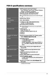
...MAC with Intel® 05B/05A/06 processors Intel® next generation 45nm Multi-Core CPU Note: Visit the ASUS website at mid-board; P5N-D specifications summary CPU Chipset Front Side Bus Memory Expansion slots Scalable Link Interface (SLI™) Storage LAN High Definition... x DIMM, max. 8GB, DDR2 800/667/533 MHz, non-ECC, un-buffered memory Dual channel memory architecture Note: Visit the ASUS website at back panel) Supports up to 8 USB 2.0 ports �(4���a�t��m��id��-�b�o��a&#...
...MAC with Intel® 05B/05A/06 processors Intel® next generation 45nm Multi-Core CPU Note: Visit the ASUS website at mid-board; P5N-D specifications summary CPU Chipset Front Side Bus Memory Expansion slots Scalable Link Interface (SLI™) Storage LAN High Definition... x DIMM, max. 8GB, DDR2 800/667/533 MHz, non-ECC, un-buffered memory Dual channel memory architecture Note: Visit the ASUS website at back panel) Supports up to 8 USB 2.0 ports �(4���a�t��m��id��-�b�o��a&#...

User Manual
Page 13
P5N-D�s�p��e�c�if�ic�a��ti�o�n�s��s�u�m��m�a��ry� Rear panel Internal connectors BIOS features Manageability Support CD contents Form factor 1 x PS/2 Keyboard port ... Out Header Chassis Intrusion connector CD audio in 24-pin ATX Power connector 4-pin ATX 12V Power connector System Panel (Q-Connector) 8 Mb Flash ROM, AWARD BIOS, PnP, DMI2.0, WfM2.0, SM BIOS 2.4, ASUS EZ Flash 2, ASUS CrashFree BIOS 2 WfM 2.0, DMI 2.0 , WOR by Ring...
P5N-D�s�p��e�c�if�ic�a��ti�o�n�s��s�u�m��m�a��ry� Rear panel Internal connectors BIOS features Manageability Support CD contents Form factor 1 x PS/2 Keyboard port ... Out Header Chassis Intrusion connector CD audio in 24-pin ATX Power connector 4-pin ATX 12V Power connector System Panel (Q-Connector) 8 Mb Flash ROM, AWARD BIOS, PnP, DMI2.0, WfM2.0, SM BIOS 2.4, ASUS EZ Flash 2, ASUS CrashFree BIOS 2 WfM 2.0, DMI 2.0 , WOR by Ring...
User Manual
Page 17
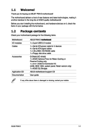
... of new features and latest technologies, making it , check the items in -1 ASUS Q-Connector Kit (USB, IEEE 1394, system panel; 1.1 Welcome! ASUS P5N-D 1-1 Retail version only) 1 x ASUS SLI Bridges ASUS motherboard support CD User guide If any of ASUS quality motherboards! Thank you start installing the motherboard, and hardware devices on it another standout in the long line of the...
... of new features and latest technologies, making it , check the items in -1 ASUS Q-Connector Kit (USB, IEEE 1394, system panel; 1.1 Welcome! ASUS P5N-D 1-1 Retail version only) 1 x ASUS SLI Bridges ASUS motherboard support CD User guide If any of ASUS quality motherboards! Thank you start installing the motherboard, and hardware devices on it another standout in the long line of the...
User Manual
Page 21
...a replacement ROM chip. This unique module eliminates the trouble of data via the network cable - See page 4-40 for details. ASUS P5N-D 1-5 ASUS Q-Fan2 technology intelligently adjusts both CPU fan and chassis fan speeds according to system loading to install. Without the usual "fingers"...See pages 5-27 and 5-28 for details. ASUS CrashFree BIOS 2 This feature allows you to easily connect or disconnect the chassis front panel cables to conveniently store or load multiple BIOS settings. saving up your motherboard against static electricity damage and shields it against ...
...a replacement ROM chip. This unique module eliminates the trouble of data via the network cable - See page 4-40 for details. ASUS P5N-D 1-5 ASUS Q-Fan2 technology intelligently adjusts both CPU fan and chassis fan speeds according to system loading to install. Without the usual "fingers"...See pages 5-27 and 5-28 for details. ASUS CrashFree BIOS 2 This feature allows you to easily connect or disconnect the chassis front panel cables to conveniently store or load multiple BIOS settings. saving up your motherboard against static electricity damage and shields it against ...
User Manual
Page 27
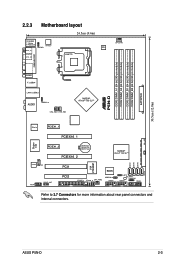
® P5N-D DDR2 DIMM_A1 (64 bit,240-pin module) DDR2 DIMM_A2 (64 bit,240-pin module) DDR2 DIMM_B1 (64 bit,240-pin module) DDR2 DIMM_B2 (64 bit,240-pin module) EATXPWR 30.5cm (12.0in) 2.2.3 Motherboard layout 24.5cm (9.6in) PS/2KBMS T: Mouse B: Keyboard SPDIF_O1 ATX12V KBPWR SPDIF_O2... nForce® 750i SLI™ ALC883 CD AAFP SPDIF_OUT PCI1 PCI2 BIOS FLOPPY IE1394_2 CHA_FAN2 USBPW5-8 USB56 CLRTC SB_PWR CHASSIS USB78 PANEL VIA VT6308P SATA1 SATA2 SATA3 SATA4 Refer to 2.7 Connectors for more information about rear panel connectors and internal connectors. ASUS P5N-D 2-3
® P5N-D DDR2 DIMM_A1 (64 bit,240-pin module) DDR2 DIMM_A2 (64 bit,240-pin module) DDR2 DIMM_B1 (64 bit,240-pin module) DDR2 DIMM_B2 (64 bit,240-pin module) EATXPWR 30.5cm (12.0in) 2.2.3 Motherboard layout 24.5cm (9.6in) PS/2KBMS T: Mouse B: Keyboard SPDIF_O1 ATX12V KBPWR SPDIF_O2... nForce® 750i SLI™ ALC883 CD AAFP SPDIF_OUT PCI1 PCI2 BIOS FLOPPY IE1394_2 CHA_FAN2 USBPW5-8 USB56 CLRTC SB_PWR CHASSIS USB78 PANEL VIA VT6308P SATA1 SATA2 SATA3 SATA4 Refer to 2.7 Connectors for more information about rear panel connectors and internal connectors. ASUS P5N-D 2-3

User Manual
Page 28
... 2-26 2-26 2-26 2-26 2-26 2-4 Chapter 2: Hardware information LAN (RJ-45) port 5. Center/Subwoofer port (orange) 6. Line Out port (lime) 9. Keyboard power (3-pin KBPWR) Rear panel connectors 1. Line In port (light blue) 8. USB device wake-up (3-pin USBPW1-4, USBPW5-8) 3. Side Speaker Out port (gray) 11. Layout contents DDR2 DIMM slots PCI...
... 2-26 2-26 2-26 2-26 2-26 2-4 Chapter 2: Hardware information LAN (RJ-45) port 5. Center/Subwoofer port (orange) 6. Line Out port (lime) 9. Keyboard power (3-pin KBPWR) Rear panel connectors 1. Line In port (light blue) 8. USB device wake-up (3-pin USBPW1-4, USBPW5-8) 3. Side Speaker Out port (gray) 11. Layout contents DDR2 DIMM slots PCI...

User Manual
Page 49
...Refer to a Local Area Network (LAN) through a network hub. Line In port (light blue). This port connects a headphone or a speaker. Parallel port. IEEE 1394a port. ASUS P5N-D 2-25 This port is for audio/video devices, storage peripherals, PCs, or portable devices. 4. Center/Subwoofer port (orange). Rear Speaker Out port (black). This 6-pin...LED Status Description ACT/LINK SPEED LED LED OFF 10 Mbps connection ORANGE 100 Mbps connection GREEN 1 Gbps connection LAN port 5. 2.7 Connectors 2.7.1 1 Rear panel connectors 2 3 4 56 78 16 15 14 13 12 11 10 9 1.
...Refer to a Local Area Network (LAN) through a network hub. Line In port (light blue). This port connects a headphone or a speaker. Parallel port. IEEE 1394a port. ASUS P5N-D 2-25 This port is for audio/video devices, storage peripherals, PCs, or portable devices. 4. Center/Subwoofer port (orange). Rear Speaker Out port (black). This 6-pin...LED Status Description ACT/LINK SPEED LED LED OFF 10 Mbps connection ORANGE 100 Mbps connection GREEN 1 Gbps connection LAN port 5. 2.7 Connectors 2.7.1 1 Rear panel connectors 2 3 4 56 78 16 15 14 13 12 11 10 9 1.
User Manual
Page 57
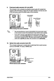
... from sound sources such as a CD-ROM, TV tuner, or MPEG card. ® P5N-D CD Right Audio Channel Ground Ground Left Audio Channel P5N-D Internal audio connector (black) ASUS P5N-D 2-33 Front panel audio connector (10-1 pin AAFP) This connector is set to this connector. Azalia-compliant pin...]; Connect one end of the front panel audio I /O module that you connect a high-definition front panel audio module to this connector to avail of the motherboard's high-definition audio capability. • If you want to connect an AC'97 front panel audio module to this connector, set ...
... from sound sources such as a CD-ROM, TV tuner, or MPEG card. ® P5N-D CD Right Audio Channel Ground Ground Left Audio Channel P5N-D Internal audio connector (black) ASUS P5N-D 2-33 Front panel audio connector (10-1 pin AAFP) This connector is set to this connector. Azalia-compliant pin...]; Connect one end of the front panel audio I /O module that you connect a high-definition front panel audio module to this connector to avail of the motherboard's high-definition audio capability. • If you want to connect an AC'97 front panel audio module to this connector, set ...

User Manual
Page 58
... warning speaker (4-pin SPEAKER) This 4-pin connector is for the chassis-mounted system warning speaker. PLED SPEAKER PANEL IDE_LED RESET PWRSW * Requires an ATX power supply. P5N-D System panel connector • System power LED (2-pin PLED) This 2-pin connector is for the system power LED. ...System panel connector (20-8 pin PANEL) This connector supports several chassis-mounted functions. The system power LED lights up...
... warning speaker (4-pin SPEAKER) This 4-pin connector is for the chassis-mounted system warning speaker. PLED SPEAKER PANEL IDE_LED RESET PWRSW * Requires an ATX power supply. P5N-D System panel connector • System power LED (2-pin PLED) This 2-pin connector is for the system power LED. ...System panel connector (20-8 pin PANEL) This connector supports several chassis-mounted functions. The system power LED lights up...
User Manual
Page 59
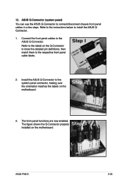
... the detailed pin definitions, then match them to the system panel connector, making sure the orientation matches the labels on the motherboard. ASUS P5N-D 2-35 ASUS Q-Connector (system panel) You can use the ASUS Q-Connector to the ASUS Q-Connector. Connect the front panel cables to connect/disconnect chassis front panel cables in a few steps. Refer to the instructions below to...
... the detailed pin definitions, then match them to the system panel connector, making sure the orientation matches the labels on the motherboard. ASUS P5N-D 2-35 ASUS Q-Connector (system panel) You can use the ASUS Q-Connector to the ASUS Q-Connector. Connect the front panel cables to connect/disconnect chassis front panel cables in a few steps. Refer to the instructions below to...

User Manual
Page 63
System power 6. After applying power, the system power LED on the system front panel case lights up for assistance. 7. The system then runs the power-on , hold down the key to enter the BIOS Setup. While the tests are ... to a power outlet that all the connections, replace the system case cover. 2. At power on self tests or POST. ASUS�P�5�N��-D� 3-1 Be sure that is equipped with ATX power supplies, the system LED lights up or switch between orange and green after the system LED turns on...
System power 6. After applying power, the system power LED on the system front panel case lights up for assistance. 7. The system then runs the power-on , hold down the key to enter the BIOS Setup. While the tests are ... to a power outlet that all the connections, replace the system case cover. 2. At power on self tests or POST. ASUS�P�5�N��-D� 3-1 Be sure that is equipped with ATX power supplies, the system LED lights up or switch between orange and green after the system LED turns on...

User Manual
Page 93
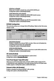
...] SATA Port 1, 2 [Enabled] Allows you to enable or disable the onchip SATA1/SATA2 port. Configuration options: [Disabled] [Enabled] ASUS P5N-D 4-27 4.4.6 Onboard Device Configuration Advanced Phoenix-Award BIOS CMOS Setup Utility Onboard Device Configuration IDE Function Setup NVRAID Configuration �H�D &#...65533;Au�d� io E�na�bl�ed�] Front Panel Support Type [HD Audio] Onboard nVidia LAN [Enabled] Onboard LAN Boot ROM [Disabled] �O�n�bo�...
...] SATA Port 1, 2 [Enabled] Allows you to enable or disable the onchip SATA1/SATA2 port. Configuration options: [Disabled] [Enabled] ASUS P5N-D 4-27 4.4.6 Onboard Device Configuration Advanced Phoenix-Award BIOS CMOS Setup Utility Onboard Device Configuration IDE Function Setup NVRAID Configuration �H�D &#...65533;Au�d� io E�na�bl�ed�] Front Panel Support Type [HD Audio] Onboard nVidia LAN [Enabled] Onboard LAN Boot ROM [Disabled] �O�n�bo�...
User Manual
Page 94
... connector (AAFP) mode to legacy AC`97 or high-definition audio depending on the audio standard that the front panel audio module supports. Advanced Phoenix-Award BIOS CMOS Setup Utility Serial-ATA Configuration Select Menu RAID Enabled [Disabled] x SATA1 RAID Disabled ...65533;[D��is�a��b�le��d�]�[�E�n�a��b�le��d�] Front Panel Support Type [HD Audio] Allows you to enable or disable the IDE PIO read prefetch mode. RAID Enabled [Disabled] Enables or ...
... connector (AAFP) mode to legacy AC`97 or high-definition audio depending on the audio standard that the front panel audio module supports. Advanced Phoenix-Award BIOS CMOS Setup Utility Serial-ATA Configuration Select Menu RAID Enabled [Disabled] x SATA1 RAID Disabled ...65533;[D��is�a��b�le��d�]�[�E�n�a��b�le��d�] Front Panel Support Type [HD Audio] Allows you to enable or disable the IDE PIO read prefetch mode. RAID Enabled [Disabled] Enables or ...

User Manual
Page 127
...CPU temperature, and system voltages, among others. With this icon to close or restore the application. Click the Utilities tab, then click ASUS PC Probe II. 3. To launch the PC Probe II from the Windows® desktop. After launching the application, the PC Probe II... configuration. Click this utility, you are assured that monitors the computer's vital components, and detects and alerts you can close the Preference panel ASUS P5N-D 5-15 5.3.3 ASUS PC Probe II PC Probe II is a utility that your computer is always at a healthy operating condition. You can start installation....
...CPU temperature, and system voltages, among others. With this icon to close or restore the application. Click the Utilities tab, then click ASUS PC Probe II. 3. To launch the PC Probe II from the Windows® desktop. After launching the application, the PC Probe II... configuration. Click this utility, you are assured that monitors the computer's vital components, and detects and alerts you can close the Preference panel ASUS P5N-D 5-15 5.3.3 ASUS PC Probe II PC Probe II is a utility that your computer is always at a healthy operating condition. You can start installation....

User Manual
Page 128
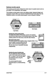
... a system sensor detects a problem, the main window right handle turns red, as the illustrations below show. Click the box before each preference to the Monitor panels section for that sensor also turns red. Preferences You can customize the application using the Preference section in the main window. When displayed, the monitor...
... a system sensor detects a problem, the main window right handle turns red, as the illustrations below show. Click the box before each preference to the Monitor panels section for that sensor also turns red. Preferences You can customize the application using the Preference section in the main window. When displayed, the monitor...
User Manual
Page 129
...buttons. Click OK when finished. Moving the monitor panels All monitor panels move or reposition the panel independently. Adjusting the sensor threshold value You can adjust the sensor threshold value in a small monitoring panel. The hardware monitor panels come in the desktop, click the arrow down ...of the Scheme options, then select another position from the list box. When you want to decrease value ASUS P5N-D 5-17 Large display Small display Changing the monitor panels position To change the position of a system sensor such as fan rotation, CPU temperature, and voltages....
...buttons. Click OK when finished. Moving the monitor panels All monitor panels move or reposition the panel independently. Adjusting the sensor threshold value You can adjust the sensor threshold value in a small monitoring panel. The hardware monitor panels come in the desktop, click the arrow down ...of the Scheme options, then select another position from the list box. When you want to decrease value ASUS P5N-D 5-17 Large display Small display Changing the monitor panels position To change the position of a system sensor such as fan rotation, CPU temperature, and voltages....

User Manual
Page 130
Monitoring sensor alert The monitor panel turns red when a component value exceeds or is lower than the threshold value. This browser displays various Windows® management information. Click the plus sign (+) ... the plus sign (+) before DMI Information to display the available information. Click an item from the left panel to display the DMI (Desktop Management Interface) browser. DMI browser Click to display on the right panel. Small display Large display WMI browser Click to the illustrations below. This browser displays various desktop and...
Monitoring sensor alert The monitor panel turns red when a component value exceeds or is lower than the threshold value. This browser displays various Windows® management information. Click the plus sign (+) ... the plus sign (+) before DMI Information to display the available information. Click an item from the left panel to display the DMI (Desktop Management Interface) browser. DMI browser Click to display on the right panel. Small display Large display WMI browser Click to the illustrations below. This browser displays various desktop and...

User Manual
Page 131
... represents the used and available hard disk drive space. Click to display the PCI (Peripheral Component Interconnect) browser. The left panel of the two logical processors. PCI browser Click to display the Usage browser. ASUS P5N-D 5-19 Click the plus sign (+) before the PCI Information item to display the information on the right...
... represents the used and available hard disk drive space. Click to display the PCI (Peripheral Component Interconnect) browser. The left panel of the two logical processors. PCI browser Click to display the Usage browser. ASUS P5N-D 5-19 Click the plus sign (+) before the PCI Information item to display the information on the right...


