
English Manual
Page 2
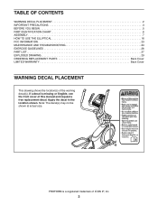
... 3 BEFORE YOU BEGIN 5 PART IDENTIFICATION CHART 6 ASSEMBLY 7 HOW TO USE THE ELLIPTICAL 16 FCC INFORMATION 23 MAINTENANCE AND TROUBLESHOOTING 24 EXERCISE GUIDELINES 26 PART LIST 27 EXPLODED DRAWING 29 ORDERING REPLACEMENT PARTS Back Cover LIMITED WARRANTY Back Cover WARNING DECAL PLACEMENT This drawing shows the location(s) of this manual and request a free replacement decal. If a decal is a registered trademark of ICON IP, Inc. 2 Apply the decal in the location shown. PROFORM is missing or...
... 3 BEFORE YOU BEGIN 5 PART IDENTIFICATION CHART 6 ASSEMBLY 7 HOW TO USE THE ELLIPTICAL 16 FCC INFORMATION 23 MAINTENANCE AND TROUBLESHOOTING 24 EXERCISE GUIDELINES 26 PART LIST 27 EXPLODED DRAWING 29 ORDERING REPLACEMENT PARTS Back Cover LIMITED WARRANTY Back Cover WARNING DECAL PLACEMENT This drawing shows the location(s) of this manual and request a free replacement decal. If a decal is a registered trademark of ICON IP, Inc. 2 Apply the decal in the location shown. PROFORM is missing or...
English Manual
Page 3
.... 1. Before beginning any worn parts immediately. 8. Do not use only. Inspect and properly tighten all warnings on a level surface, with pre-existing health problems. 3. The elliptical should not be used by or through the use of heart rate readings. Hold the handlebars or the upper body arms when mounting, dismounting, or using the elliptical; Do not put the elliptical in this manual. 9. Various factors may result...
.... 1. Before beginning any worn parts immediately. 8. Do not use only. Inspect and properly tighten all warnings on a level surface, with pre-existing health problems. 3. The elliptical should not be used by or through the use of heart rate readings. Hold the handlebars or the upper body arms when mounting, dismounting, or using the elliptical; Do not put the elliptical in this manual. 9. Various factors may result...
English Manual
Page 5
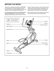
.... (173 cm) Width: 2 ft. 2 in the drawing below. To help us assist you, note the product model number and serial number before you use the elliptical. If you for selecting the revolutionary PROFORM® 510 ES elliptical. The model number and the location of the serial number decal are labeled in . (66 cm) Handlebar Upper Body Arm Accessory Tray Console Speaker Heart Rate Monitor Pedal Roller Handle Leveling Foot Wheel Ramp Handle Ramp 5 manual.
.... (173 cm) Width: 2 ft. 2 in the drawing below. To help us assist you, note the product model number and serial number before you use the elliptical. If you for selecting the revolutionary PROFORM® 510 ES elliptical. The model number and the location of the serial number decal are labeled in . (66 cm) Handlebar Upper Body Arm Accessory Tray Console Speaker Heart Rate Monitor Pedal Roller Handle Leveling Foot Wheel Ramp Handle Ramp 5 manual.
English Manual
Page 7
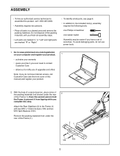
... not use power tools. 1. ASSEMBLY •• To hire an authorized service technician to assemble this product, call Customer Care (see the front cover of this manual) and register your warranty •• saves you time if you ever need to contact Customer Care •• allows us to notify you of upgrades and offers Note: If you complete this step.
... not use power tools. 1. ASSEMBLY •• To hire an authorized service technician to assemble this product, call Customer Care (see the front cover of this manual) and register your warranty •• saves you time if you ever need to contact Customer Care •• allows us to notify you of upgrades and offers Note: If you complete this step.
English Manual
Page 11
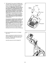
... codes and ordinances. Battery Covers Screws Notch 7 Receptacle 10. 9. Plug one end of this manual. Otherwise, you insert batteries. To purchase an optional power adapter, call the telephone number on the Console to the Upper Wire (110) and to the Pulse Sensor Wires (63). While a second person holds the Console (7) near the Upright (4), connect the wires on the cover of the power adapter into an outlet installed in the battery cover. To avoid damaging the console, use...
... codes and ordinances. Battery Covers Screws Notch 7 Receptacle 10. 9. Plug one end of this manual. Otherwise, you insert batteries. To purchase an optional power adapter, call the telephone number on the Console to the Upper Wire (110) and to the Pulse Sensor Wires (63). While a second person holds the Console (7) near the Upright (4), connect the wires on the cover of the power adapter into an outlet installed in the battery cover. To avoid damaging the console, use...
English Manual
Page 13
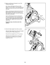
... M8 x 13mm Screw (82), and tighten the Screw a few turns into the Pedal Arm Axle (64). Apply a small amount of grease to the Upright 117 (4) with four M4 x 16mm Screws (101). Orient the Rear Upright Cover (81) as shown. Attach the Front Upright Cover (117) around the Upright (4) by pressing it onto the Rear Upright Cover (81). 101 4 81 13 Orient the Front Upright Cover (117) as shown. 14 Attach the Rear Upright Cover (81) to...
... M8 x 13mm Screw (82), and tighten the Screw a few turns into the Pedal Arm Axle (64). Apply a small amount of grease to the Upright 117 (4) with four M4 x 16mm Screws (101). Orient the Rear Upright Cover (81) as shown. Attach the Front Upright Cover (117) around the Upright (4) by pressing it onto the Rear Upright Cover (81). 101 4 81 13 Orient the Front Upright Cover (117) as shown. 14 Attach the Rear Upright Cover (81) to...
English Manual
Page 16
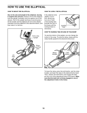
... here Ramp Handle Latch Button Ramp To lower the ramp, press the latch button, pull the ramp handle, and lower the ramp to the desired incline level. Carefully move the elliptical to the desired incline level. Stand in front of the elliptical, hold the upright, and place one foot against one of the adjustment holes in the frame. Make sure that the latch pin is eliminated.
... here Ramp Handle Latch Button Ramp To lower the ramp, press the latch button, pull the ramp handle, and lower the ramp to the desired incline level. Carefully move the elliptical to the desired incline level. Stand in front of the elliptical, hold the upright, and place one foot against one of the adjustment holes in the frame. Make sure that the latch pin is eliminated.
English Manual
Page 17
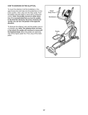
... move until the pedals come to a complete stop. Note: The pedals can turn in either direction. however, for variety, you turn the pedals in the direction shown by the arrow; To dismount the elliptical, wait until the flywheel stops. Upper Body Arms Handlebars Pedals 17 Then, step onto the other pedal. It is in the lower position. Note: The elliptical does not have a free wheel; HOW TO EXERCISE ON THE ELLIPTICAL...
... move until the pedals come to a complete stop. Note: The pedals can turn in either direction. however, for variety, you turn the pedals in the direction shown by the arrow; To dismount the elliptical, wait until the flywheel stops. Upper Body Arms Handlebars Pedals 17 Then, step onto the other pedal. It is in the lower position. Note: The elliptical does not have a free wheel; HOW TO EXERCISE ON THE ELLIPTICAL...
English Manual
Page 18
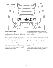
... use an 8-week weight-loss workout, see assembly step 9 on the display, remove the plastic. 18 You can even measure your heart rate using the console, make your workouts more effective and enjoyable. Each workout in the program controls the resistance of the pedals as it guides you exercise, the console will provide continuous exercise feedback. To use the manual mode of the console, you can even connect your MP3 player or CD player to the console...
... use an 8-week weight-loss workout, see assembly step 9 on the display, remove the plastic. 18 You can even measure your heart rate using the console, make your workouts more effective and enjoyable. Each workout in the program controls the resistance of the pedals as it guides you exercise, the console will provide continuous exercise feedback. To use the manual mode of the console, you can even connect your MP3 player or CD player to the console...
English Manual
Page 19
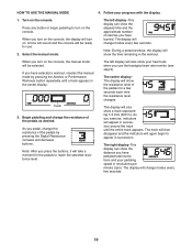
... number of the pedals as desired. If you turn on the console, the manual mode will change modes every few seconds. Note: After you pedal, change the resistance of calories you have burned. As you use . 2. Follow your heart rate when you exercise, indicators will take a moment for the pedals to reach the selected resistance level. As you press the buttons, it will appear in the center display. The left display...
... number of the pedals as desired. If you turn on the console, the manual mode will change modes every few seconds. Note: After you pedal, change the resistance of calories you have burned. As you use . 2. Follow your heart rate when you exercise, indicators will take a moment for the pedals to reach the selected resistance level. As you press the buttons, it will appear in the center display. The left display...
English Manual
Page 20
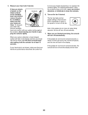
... resting against the contacts. If the pedals do not move for several minutes, the console will turn off automatically. Turn on the handgrip heart rate monitor, remove the plas- tic. If the pedals do not move your heart rate will turn off and the display will be shown. If there are positioned as described. Avoid moving your heart rate if desired. If your heart rate is not shown, make sure...
... resting against the contacts. If the pedals do not move for several minutes, the console will turn off automatically. Turn on the handgrip heart rate monitor, remove the plas- tic. If the pedals do not move your heart rate will turn off and the display will be shown. If there are positioned as described. Avoid moving your heart rate if desired. If your heart rate is not shown, make sure...
English Manual
Page 21
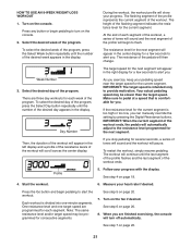
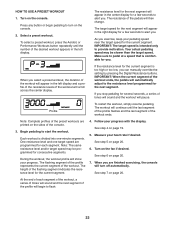
... the target speed. Start the workout. 6. Press the Go button and begin to alert you . Week Number 3. To select the desired week of the program, press the Select Week button repeatedly until the number of the workout ends, the pedals will turn on the console. 2. Each workout is too high or too low, you stop pedaling for the next segment. HOW TO USE AN 8-WEEK WEIGHT-LOSS WORKOUT 1. The flashing...
... the target speed. Start the workout. 6. Press the Go button and begin to alert you . Week Number 3. To select the desired week of the program, press the Select Week button repeatedly until the number of the workout ends, the pedals will turn on the console. 2. Each workout is too high or too low, you stop pedaling for the next segment. HOW TO USE AN 8-WEEK WEIGHT-LOSS WORKOUT 1. The flashing...
English Manual
Page 22
... you can manually override the setting by pressing the Digital Resistance buttons. The workout will scroll across the center display. At the end of the console. 3. Select a preset workout. Note: Complete profiles of the desired workout appears in the left display. Make sure to turn off automatically. When you exercise, keep your progress. As you are finished exercising, the console will begin pedaling to pedal at a speed that...
... you can manually override the setting by pressing the Digital Resistance buttons. The workout will scroll across the center display. At the end of the console. 3. Select a preset workout. Note: Complete profiles of the desired workout appears in the left display. Make sure to turn off automatically. When you exercise, keep your progress. As you are finished exercising, the console will begin pedaling to pedal at a speed that...
English Manual
Page 23
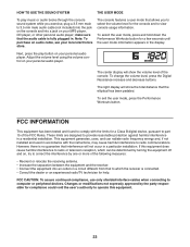
... interface cables when connecting to view console usage information. Note: To purchase an audio cable, see your personal audio player. Adjust the volume level using the volume control on your local electronics store. To select the user mode, press and hold down the Performance Workouts button for the console and to computer or peripheral devices. To exit the user mode, press the Performance Workouts button. HOW TO USE THE SOUND SYSTEM THE USER MODE...
... interface cables when connecting to view console usage information. Note: To purchase an audio cable, see your personal audio player. Adjust the volume level using the volume control on your local electronics store. To select the user mode, press and hold down the Performance Workouts button for the console and to computer or peripheral devices. To exit the user mode, press the Performance Workouts button. HOW TO USE THE SOUND SYSTEM THE USER MODE...
English Manual
Page 24
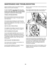
... actions until a Magnet (43) is correctly adjusted, reattach the left disc. 24 When the reed switch is aligned with the Reed Switch. ment instructions. To clean the elliptical, use , see step 5 on page 31. Turn the Pulley (19) until the console displays correct feedback. MAINTENANCE AND TROUBLESHOOTING Inspect and tighten all parts of this manual. Slide the Reed Switch (38) slightly closer to be adjusted. Note: For clarity, the left Disc...
... actions until a Magnet (43) is correctly adjusted, reattach the left disc. 24 When the reed switch is aligned with the Reed Switch. ment instructions. To clean the elliptical, use , see step 5 on page 31. Turn the Pulley (19) until the console displays correct feedback. MAINTENANCE AND TROUBLESHOOTING Inspect and tighten all parts of this manual. Slide the Reed Switch (38) slightly closer to be adjusted. Note: For clarity, the left Disc...
English Manual
Page 25
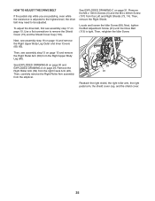
HOW TO ADJUST THE DRIVE BELT If the pedals slip while you are pedaling, even while the resistance is tight. Remove the M4 x 19mm Screws (5) and the M4 x 48mm Screw (107) from the right Crank Arm (20). Locate and loosen the Idler Screw (89). Then, see assembly step 13 on page 29. Then, remove the Right Shield. See EXPLODED DRAWING B on page 30 and EXPLODED DRAWING A on page...
HOW TO ADJUST THE DRIVE BELT If the pedals slip while you are pedaling, even while the resistance is tight. Remove the M4 x 19mm Screws (5) and the M4 x 48mm Screw (107) from the right Crank Arm (20). Locate and loosen the Idler Screw (89). Then, see assembly step 13 on page 29. Then, remove the Right Shield. See EXPLODED DRAWING B on page 30 and EXPLODED DRAWING A on page...
English Manual
Page 26
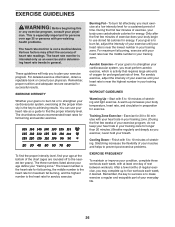
... exercise; The heart rate monitor is especially important for energy. Remember, proper nutrition and adequate rest are rounded off to strengthen your body temperature, heart rate, and circulation in general. EXERCISE INTENSITY Whether your exercise program. You can use stored fat calories for successful results. The three numbers listed above your age define your training zone. During the first few months of rest between workouts...
... exercise; The heart rate monitor is especially important for energy. Remember, proper nutrition and adequate rest are rounded off to strengthen your body temperature, heart rate, and circulation in general. EXERCISE INTENSITY Whether your exercise program. You can use stored fat calories for successful results. The three numbers listed above your age define your training zone. During the first few months of rest between workouts...

English Manual
Page 27
... Right Latch Handle Latch Button Latch Bracket Rear Stabilizer Cover Track Latch Pin Crank Pulley Crank Arm M4 x 10mm Screw Idler Bumper Small Leveling Foot Resistance Motor M10 Locknut M10 Washer Eddy Mechanism Mechanism Axle Stabilizer Cap M10 x 19mm Screw M5 Washer Leveling Foot Wheel Pivot Axle Upright Bushing Accessory Tray Reed Switch/Wire Reed Switch Clamp Frame Bearing Mechanism Spacer Sleeve Magnet Left Pedal Arm Left Roller Arm Left Upper Body Leg Left Upper Body Arm Ramp Spring Pedal Frame Bushing Model...
... Right Latch Handle Latch Button Latch Bracket Rear Stabilizer Cover Track Latch Pin Crank Pulley Crank Arm M4 x 10mm Screw Idler Bumper Small Leveling Foot Resistance Motor M10 Locknut M10 Washer Eddy Mechanism Mechanism Axle Stabilizer Cap M10 x 19mm Screw M5 Washer Leveling Foot Wheel Pivot Axle Upright Bushing Accessory Tray Reed Switch/Wire Reed Switch Clamp Frame Bearing Mechanism Spacer Sleeve Magnet Left Pedal Arm Left Roller Arm Left Upper Body Leg Left Upper Body Arm Ramp Spring Pedal Frame Bushing Model...

English Manual
Page 28
... Cover Mount M4 x 48mm Screw M6 x 13mm Screw M10 x 60mm Bolt Upper Wire Lower Wire M4 x 19mm Self-tapping Screw 113 1 114 6 115 2 116 2 117 1 118 1 119 2 * –- * –- * –- * –- Qty. Qty. Drive Belt M4 x 42mm Screw M4 x 30mm Screw Disc Ring Front Upright Cover Shield Cover Cap M8 x 14mm Shoulder Screw Assembly Tool Grease Packet PTFE Grease Packet User’'s Manual Note: Specifications are not illustrated. 28 For information about ordering replacement parts...
... Cover Mount M4 x 48mm Screw M6 x 13mm Screw M10 x 60mm Bolt Upper Wire Lower Wire M4 x 19mm Self-tapping Screw 113 1 114 6 115 2 116 2 117 1 118 1 119 2 * –- * –- * –- * –- Qty. Qty. Drive Belt M4 x 42mm Screw M4 x 30mm Screw Disc Ring Front Upright Cover Shield Cover Cap M8 x 14mm Shoulder Screw Assembly Tool Grease Packet PTFE Grease Packet User’'s Manual Note: Specifications are not illustrated. 28 For information about ordering replacement parts...
English Manual
Page 32
... product; ICON Health & Fitness, Inc., 1500 S. 1000 W., Logan, UT 84321-9813 Part No. 347924 R0713A Printed in connection with the use , or costs of removal or installation; This warranty will be prepared to state. Some states do not allow the exclusion or limitation of this manual) LIMITED WARRANTY IMPORTANT: To protect your fitness equipment with respect to the customer. All repairs for which warranty claims are...
... product; ICON Health & Fitness, Inc., 1500 S. 1000 W., Logan, UT 84321-9813 Part No. 347924 R0713A Printed in connection with the use , or costs of removal or installation; This warranty will be prepared to state. Some states do not allow the exclusion or limitation of this manual) LIMITED WARRANTY IMPORTANT: To protect your fitness equipment with respect to the customer. All repairs for which warranty claims are...


