User Guide
Page 11
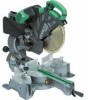
... Digital display (Only C12LSH) 6 mm Knob bolt (Optional accessory) Holder (Optional Accessory) Steel squar 6 mm Wing nut (Optional accessory) Height adjustment bolt 6 mm (Optional accessory) Base surface Stopper (Optional Accessory) 6 mm Knob bolt (Optional accessory) Sub fence (A) Knob (B) Screw holder 6 ...mm Knob bolt Vise shaft Slide seuring knob (B) Fence 6 mm Wing bolt Vise plate Knob Laser line Groove Bevel scale Miter scale Crown molding vise ass'y (Optional accessory)...
... Digital display (Only C12LSH) 6 mm Knob bolt (Optional accessory) Holder (Optional Accessory) Steel squar 6 mm Wing nut (Optional accessory) Height adjustment bolt 6 mm (Optional accessory) Base surface Stopper (Optional Accessory) 6 mm Knob bolt (Optional accessory) Sub fence (A) Knob (B) Screw holder 6 ...mm Knob bolt Vise shaft Slide seuring knob (B) Fence 6 mm Wing bolt Vise plate Knob Laser line Groove Bevel scale Miter scale Crown molding vise ass'y (Optional accessory)...

User Guide
Page 12
...; (B) fi Lukkovako fl Yläpinta ‡ 6 mm:n siipipultti (A) English Switch (For digital display) Marking (Pre-marked) Line Warning sign 5 mm Machine screw 6 mm Depth adjustment bolt Stopper holder Bottom line of the groove 5 mm Screw Poly-V-belt Pulley (A) Pulley (B) Locking groove Upper surface 6 mm Wing bolt (A) 11
...; (B) fi Lukkovako fl Yläpinta ‡ 6 mm:n siipipultti (A) English Switch (For digital display) Marking (Pre-marked) Line Warning sign 5 mm Machine screw 6 mm Depth adjustment bolt Stopper holder Bottom line of the groove 5 mm Screw Poly-V-belt Pulley (A) Pulley (B) Locking groove Upper surface 6 mm Wing bolt (A) 11
User Guide
Page 55
... 13. Solvents such as the mishandling of personal injury. 22. Use only original HITACHI replacement parts. 10. Adequate general or localized lighting is used only for outdoor use...instructions before turning it was intended. 7. Ensure switch is dusty. 10. PRECAUTIONS ON USING SLIDE COMPOUND MITER SAW 1. Do not wipe plastic parts with such solvent. For safe operations: 1. Keep work area... dry, clean, and free from extraction duct on this compound miter saw to reduce the risk of loose materials e.g. Remove adjusting keys and wrenches. Stay alert. Watch what you are ...
... 13. Solvents such as the mishandling of personal injury. 22. Use only original HITACHI replacement parts. 10. Adequate general or localized lighting is used only for outdoor use...instructions before turning it was intended. 7. Ensure switch is dusty. 10. PRECAUTIONS ON USING SLIDE COMPOUND MITER SAW 1. Do not wipe plastic parts with such solvent. For safe operations: 1. Keep work area... dry, clean, and free from extraction duct on this compound miter saw to reduce the risk of loose materials e.g. Remove adjusting keys and wrenches. Stay alert. Watch what you are ...

User Guide
Page 56
...slide compound miter saw with the saw blade turned upward or to cut -offs or other parts of saw blade comply with its lower guard locked in the use the saw to the side. 27. Do not use , adjustment...176; - 45° Voltage (by HITACHI. The saw blades should not be carried out correctly. 32. Do not use the slide compound miter saw with EN847-1. 24. Use only saw blades recommended by areas)* Power Input* ...V, 230 V) 1520 W 4000 min-1 595 mm × 930 mm × 710 mm C12LSH C12RSH 30 kg 29 kg Yes No Po Grasp the handle instead of residual risks in good working order ...
...slide compound miter saw with the saw blade turned upward or to cut -offs or other parts of saw blade comply with its lower guard locked in the use the saw to the side. 27. Do not use , adjustment...176; - 45° Voltage (by HITACHI. The saw blades should not be carried out correctly. 32. Do not use the slide compound miter saw with EN847-1. 24. Use only saw blades recommended by areas)* Power Input* ...V, 230 V) 1520 W 4000 min-1 595 mm × 930 mm × 710 mm C12LSH C12RSH 30 kg 29 kg Yes No Po Grasp the handle instead of residual risks in good working order ...

User Guide
Page 57
... accessories are present. UNPACKING ⅜ Carefully unpack the power tool and all necessary adjustments before inserting the plug in the OFF position. Power source Ensure that the lower guard operates smoothly CAUTION ⅜ This slide compound miter saw is adjusted so that the saw blade, follow the procedure (1) indicated below the table insert. Check to 10...
... accessories are present. UNPACKING ⅜ Carefully unpack the power tool and all necessary adjustments before inserting the plug in the OFF position. Power source Ensure that the lower guard operates smoothly CAUTION ⅜ This slide compound miter saw is adjusted so that the saw blade, follow the procedure (1) indicated below the table insert. Check to 10...
User Guide
Page 58
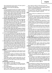
Switch operation Pulling the trigger turns the switch on the guard. Align the ink line with the saw blade groove on the ink line. (2) Miter cutting and compound cutting (Miter cutting + bevel cutting) After adjusting the height, firmly tighten the 6 mm wing bolt (A); CAUTION Always confirm that the motor head...the upper surface of the fence to the height of five locking grooves on and the saw blade may do so, loosen the 6 mm wing bolt (A) and move during cutting 2. CAUTION After adjusting the table insert for right angle cutting, the table insert will be thrust from the ...
Switch operation Pulling the trigger turns the switch on the guard. Align the ink line with the saw blade groove on the ink line. (2) Miter cutting and compound cutting (Miter cutting + bevel cutting) After adjusting the height, firmly tighten the 6 mm wing bolt (A); CAUTION Always confirm that the motor head...the upper surface of the fence to the height of five locking grooves on and the saw blade may do so, loosen the 6 mm wing bolt (A) and move during cutting 2. CAUTION After adjusting the table insert for right angle cutting, the table insert will be thrust from the ...
User Guide
Page 59
...Depending upon your choice. (1) Light up the laser marker. (On the C12RSH, only the laser marker switch.) CAUTION ⅜ When operating the digital panel, have the motor head section at least 0.2 second. The laser line is adjusted to the width of lines. otherwise, the position of a laser line ...easily discern the conformity of the saw blade at an angle to the right or more, please slide the guard to (3). Adjust the positions of the saw blade, align the laser line with the right side of the groove. (3) After adjusting the position of the saw blade and the laser line ...
...Depending upon your choice. (1) Light up the laser marker. (On the C12RSH, only the laser marker switch.) CAUTION ⅜ When operating the digital panel, have the motor head section at least 0.2 second. The laser line is adjusted to the width of lines. otherwise, the position of a laser line ...easily discern the conformity of the saw blade at an angle to the right or more, please slide the guard to (3). Adjust the positions of the saw blade, align the laser line with the right side of the groove. (3) After adjusting the position of the saw blade and the laser line ...

User Guide
Page 60
... down gradually to 107 mm high and 312 mm wide: Loosen the slide securing knob (A) (Fig. 2), grip the handle and slide the saw blade in width. (2) Workpieces up to 107 mm square. 15. Miter angle fine adjustment (1) Rotate the turntable to the miter angle you need. (2) When ...making fine adjustments of the turntable to cut . Cutting wide workpieces (Slide cutting) (1) Workpieces up the lever...
... down gradually to 107 mm high and 312 mm wide: Loosen the slide securing knob (A) (Fig. 2), grip the handle and slide the saw blade in width. (2) Workpieces up to 107 mm square. 15. Miter angle fine adjustment (1) Rotate the turntable to the miter angle you need. (2) When ...making fine adjustments of the turntable to cut . Cutting wide workpieces (Slide cutting) (1) Workpieces up the lever...

User Guide
Page 61
...sub-fence (B) counterclockwise, and engage in place during compound cutting because the saw blade may become jammed against the saw backwards with the right or left hand. Turn a height adjustment bolt 6 mm, and adjust the height of the holder. (2) After adjustment, firmly tighten the 6 mm wing nut and fasten ... When making fine adjustments of the saw blade will come into contact with the hand that the gap between the lower edge of the motor head and the workpiece will not move or slip, causing injuries. In case of compound cutting (angle + bevel) by sliding the round portion of...
...sub-fence (B) counterclockwise, and engage in place during compound cutting because the saw blade may become jammed against the saw backwards with the right or left hand. Turn a height adjustment bolt 6 mm, and adjust the height of the holder. (2) After adjustment, firmly tighten the 6 mm wing nut and fasten ... When making fine adjustments of the saw blade will come into contact with the hand that the gap between the lower edge of the motor head and the workpiece will not move or slip, causing injuries. In case of compound cutting (angle + bevel) by sliding the round portion of...
User Guide
Page 62
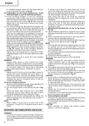
... attach the the crown molding in position (Fig 30). Adjust the Crown molding Stoppers according to the size of crown molding without tilting the saw blade and the rotation direction of the base (Fig. 31). MOUNTING AND DISMOUNTING SAW BLADE WARNING ⅜ To prevent an accident or personal ...Stoppers. (2) The crown molding vise (B) (Optional accessory) can be thrust from the receptacle before removing or installing a saw blades except 290 mm - 305 mm in diameter. After adjusting the height, firmly tighten the 6 mm wing bolt; WARNING Always firmly clamp or vise to secure the crown molding ...
... attach the the crown molding in position (Fig 30). Adjust the Crown molding Stoppers according to the size of crown molding without tilting the saw blade and the rotation direction of the base (Fig. 31). MOUNTING AND DISMOUNTING SAW BLADE WARNING ⅜ To prevent an accident or personal ...Stoppers. (2) The crown molding vise (B) (Optional accessory) can be thrust from the receptacle before removing or installing a saw blades except 290 mm - 305 mm in diameter. After adjusting the height, firmly tighten the 6 mm wing bolt; WARNING Always firmly clamp or vise to secure the crown molding ...

User Guide
Page 66
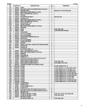
... (A) 1 187 BASE RUBBER 1 188 MACHINE SCREW M5 × 12 1 189 SPACER 1 190 LINK 1 191 ADJUSTER 1 192 NYLON CLIP 1 193 CLUTCH SCREW 1 194 CLUTCH SPRING 1 195 ADJUSTING WASHER (B) T0.5 1 196 PLATE (B) 1 197 CLUTCH SPRING 1 198A LASER MARKER 1 199 SPRING 2 200 SEAL...STOPPER HOLDER (C) 1 161 STOPPER (C) 1 162 SET PIN (A) 1 163 MACHINE SCREW (W/WASHERS) M4 × 12 2 164 INDICATOR 2 165 CAUTION LABEL (B) 1 166 SLIDE PIPE (B) 1 167 SHAFT (D) 1 168 CORD (B) 1 169 CORD COVER 1 170 BOLT WASHER M4 1 171 MACHINE SCREW M4 × 16 1 173 HINGE (A) 1 ...
... (A) 1 187 BASE RUBBER 1 188 MACHINE SCREW M5 × 12 1 189 SPACER 1 190 LINK 1 191 ADJUSTER 1 192 NYLON CLIP 1 193 CLUTCH SCREW 1 194 CLUTCH SPRING 1 195 ADJUSTING WASHER (B) T0.5 1 196 PLATE (B) 1 197 CLUTCH SPRING 1 198A LASER MARKER 1 199 SPRING 2 200 SEAL...STOPPER HOLDER (C) 1 161 STOPPER (C) 1 162 SET PIN (A) 1 163 MACHINE SCREW (W/WASHERS) M4 × 12 2 164 INDICATOR 2 165 CAUTION LABEL (B) 1 166 SLIDE PIPE (B) 1 167 SHAFT (D) 1 168 CORD (B) 1 169 CORD COVER 1 170 BOLT WASHER M4 1 171 MACHINE SCREW M4 × 16 1 173 HINGE (A) 1 ...
User Guide
Page 69
... CLUTCH SPRING 1 195 ADJUSTING WASHER (B) T0.5 1 196 PLATE (B) 1 197 CLUTCH SPRING 1 198A LASER MARKER 1 199 SPRING 2 200 SEAL LOCK HEX. SOCKET HD. SOCKET HD. BOLT M6 × 50 2 160 STOPPER HOLDER (C) 1 161 STOPPER (C) 1 162 SET PIN (A) 1 163 MACHINE SCREW (W/WASHERS) M4 × 12 2 164 INDICATOR 2 165 CAUTION LABEL (B) 1 166 SLIDE PIPE (B) 1 173... × 8 2 142 BOLT WASHER M4 2 143 BUSHING 2 144 BALL BUSHING 2 145 HOLDER (A) 1 146 KNOB BOLT M6 × 25 2 147 LOCK SPRING 2 148 SEAL LOCK HEX. C12RSH ITEM NO.
... CLUTCH SPRING 1 195 ADJUSTING WASHER (B) T0.5 1 196 PLATE (B) 1 197 CLUTCH SPRING 1 198A LASER MARKER 1 199 SPRING 2 200 SEAL LOCK HEX. SOCKET HD. SOCKET HD. BOLT M6 × 50 2 160 STOPPER HOLDER (C) 1 161 STOPPER (C) 1 162 SET PIN (A) 1 163 MACHINE SCREW (W/WASHERS) M4 × 12 2 164 INDICATOR 2 165 CAUTION LABEL (B) 1 166 SLIDE PIPE (B) 1 173... × 8 2 142 BOLT WASHER M4 2 143 BUSHING 2 144 BALL BUSHING 2 145 HOLDER (A) 1 146 KNOB BOLT M6 × 25 2 147 LOCK SPRING 2 148 SEAL LOCK HEX. C12RSH ITEM NO.
Parts List
Page 6
... 324387 HINGE SHAFT (A) 323606 BASE RUBBER 949237 MACHINE SCREW M5X12 (10 PCS.) 303854 SPACER 324376 LINK 328522 LINK 319270 ADJUSTER 305180 CLUTCH SCREW 305179 CLUTCH SPRING 962614 ADJUSTING WASHER (B) T0.5 319268 PLATE (B) 305179 CLUTCH SPRING 329863 LASER MARKER 319267 SPRING 319541 SEAL LOCK HEX. SOCKET SET ...MACHINE SCREW (W/WASHERS) M5X25 (BLACK) 945161 BRUSH CAP 999038 CARBON BRUSH (1 PAIR) 999065 CARBON BRUSH (1 PAIR) 938241 BRUSH HOLDER CAUTION LABEL (A) C12RSH NO. Parts ITEM NO. 174 175 176 179 180 181 182 183 184 185 186A 187A 188 189 *190 *190 191 193 194 195 ...
... 324387 HINGE SHAFT (A) 323606 BASE RUBBER 949237 MACHINE SCREW M5X12 (10 PCS.) 303854 SPACER 324376 LINK 328522 LINK 319270 ADJUSTER 305180 CLUTCH SCREW 305179 CLUTCH SPRING 962614 ADJUSTING WASHER (B) T0.5 319268 PLATE (B) 305179 CLUTCH SPRING 329863 LASER MARKER 319267 SPRING 319541 SEAL LOCK HEX. SOCKET SET ...MACHINE SCREW (W/WASHERS) M5X25 (BLACK) 945161 BRUSH CAP 999038 CARBON BRUSH (1 PAIR) 999065 CARBON BRUSH (1 PAIR) 938241 BRUSH HOLDER CAUTION LABEL (A) C12RSH NO. Parts ITEM NO. 174 175 176 179 180 181 182 183 184 185 186A 187A 188 189 *190 *190 191 193 194 195 ...


