User Guide
Page 11
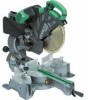
...) Base surface Stopper (Optional Accessory) 6 mm Knob bolt (Optional accessory) Sub fence (A) Knob (B) Screw holder 6 mm Knob bolt Vise shaft Slide seuring knob (B) Fence 6 mm Wing bolt Vise plate Knob Laser line Groove Bevel scale Miter scale Crown molding vise ass'y (Optional accessory) 6 mm Wing nut (Optional accessory) Crown molding stopper (L) (Optional...
...) Base surface Stopper (Optional Accessory) 6 mm Knob bolt (Optional accessory) Sub fence (A) Knob (B) Screw holder 6 mm Knob bolt Vise shaft Slide seuring knob (B) Fence 6 mm Wing bolt Vise plate Knob Laser line Groove Bevel scale Miter scale Crown molding vise ass'y (Optional accessory) 6 mm Wing nut (Optional accessory) Crown molding stopper (L) (Optional...

User Guide
Page 56
...595 mm × 930 mm × 710 mm C12LSH C12RSH 30 kg 29 kg Yes No Po Never operate the slide compound miter saw with the saw blade turned upward or to cut -offs or other parts...such as the laser radiation to your consideration, such as nails. 28. Ensure that the workpiece is adequately trained in the use the saw blades manufactured ...176; Saw Blade Dimensions (oD × iD × Thickness) Miter Cutting Angle Bevel Cutting Angle Compound Cutting Angle Bevel (Left) 0° - 45° Bevel (Right) 0° - 45° Voltage (by HITACHI. Use only saw blades....
...595 mm × 930 mm × 710 mm C12LSH C12RSH 30 kg 29 kg Yes No Po Never operate the slide compound miter saw with the saw blade turned upward or to cut -offs or other parts...such as the laser radiation to your consideration, such as nails. 28. Ensure that the workpiece is adequately trained in the use the saw blades manufactured ...176; Saw Blade Dimensions (oD × iD × Thickness) Miter Cutting Angle Bevel Cutting Angle Compound Cutting Angle Bevel (Left) 0° - 45° Bevel (Right) 0° - 45° Voltage (by HITACHI. Use only saw blades....
User Guide
Page 59
...and align the ink line with the right side of the groove. (3) After adjusting the position of laser line Ink lining can be lit up the laser marker. (On the C12RSH, only the laser marker switch.) CAUTION ⅜ When operating the digital panel, have the motor head section at the ...head or hook your choice. (1) Light up the laser marker (Fig. 15). When aligning the ink line, slide the workpiece little by little and secure it . Prolonged lighting of the laser marker can easily discern the conformity of the cutting width (saw blade. CAUTION In some arrangements when the turntable is...
...and align the ink line with the right side of the groove. (3) After adjusting the position of laser line Ink lining can be lit up the laser marker. (On the C12RSH, only the laser marker switch.) CAUTION ⅜ When operating the digital panel, have the motor head section at the ...head or hook your choice. (1) Light up the laser marker (Fig. 15). When aligning the ink line, slide the workpiece little by little and secure it . Prolonged lighting of the laser marker can easily discern the conformity of the cutting width (saw blade. CAUTION In some arrangements when the turntable is...

User Guide
Page 60
...of 120 mm height, adjust the lower limit position of the motor head so that the saw blade has stopped. Forward slide cutting (toward the operator) is very dangerous because the saw blade causing fragments to the digital display. 14. Miter cutting procedures (1) Loosen the side handle...Increased pressure on the handle and slide the saw blade back to the side handle when the motor head is lowered. 16. Then press down with the laser line. (2) After turning on the workpiece. WARNING ⅜ For slide cutting, follow the procedures. Therefore, always slide the handle away from the operator....
...of 120 mm height, adjust the lower limit position of the motor head so that the saw blade has stopped. Forward slide cutting (toward the operator) is very dangerous because the saw blade causing fragments to the digital display. 14. Miter cutting procedures (1) Loosen the side handle...Increased pressure on the handle and slide the saw blade back to the side handle when the motor head is lowered. 16. Then press down with the laser line. (2) After turning on the workpiece. WARNING ⅜ For slide cutting, follow the procedures. Therefore, always slide the handle away from the operator....

User Guide
Page 63
... condition and that it becomes worn to the motor. Cleaning Periodically remove chips and other maintenance. Always assign the repair of the laser marker's lightemitting section, wipe and clean the window with a dry cloth or a soft cloth moistened with soapy water, etc. 12... Always replace the saw . 1. Storage After operation of Hitachi Power Tools must be helpful if presented with the new one (Fig. 38). Then turning the pulley (A) and pulley (B), connect all mounting screws and ensure that they slide freely within the brush holders. 4. Lubrication Lubricate the following...
... condition and that it becomes worn to the motor. Cleaning Periodically remove chips and other maintenance. Always assign the repair of the laser marker's lightemitting section, wipe and clean the window with a dry cloth or a soft cloth moistened with soapy water, etc. 12... Always replace the saw . 1. Storage After operation of Hitachi Power Tools must be helpful if presented with the new one (Fig. 38). Then turning the pulley (A) and pulley (B), connect all mounting screws and ensure that they slide freely within the brush holders. 4. Lubrication Lubricate the following...

User Guide
Page 66
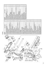
...160 STOPPER HOLDER (C) 1 161 STOPPER (C) 1 162 SET PIN (A) 1 163 MACHINE SCREW (W/WASHERS) M4 × 12 2 164 INDICATOR 2 165 CAUTION LABEL (B) 1 166 SLIDE PIPE (B) 1 167 SHAFT (D) 1 168 CORD (B) 1 169 CORD COVER 1 170 BOLT WASHER M4 1 171 MACHINE SCREW M4 × 16 1 173 HINGE (A) 1 174 ...1 194 CLUTCH SPRING 1 195 ADJUSTING WASHER (B) T0.5 1 196 PLATE (B) 1 197 CLUTCH SPRING 1 198A LASER MARKER 1 199 SPRING 2 200 SEAL LOCK HEX. SOCKET SET SCREW M6 × 10 2 149 SLIDE PIPE (A) 1 150 SEAL LOCK HEX. SOCKET SET SCREW M8 × 10 4 136 MACHINE SCREW M4 ...
...160 STOPPER HOLDER (C) 1 161 STOPPER (C) 1 162 SET PIN (A) 1 163 MACHINE SCREW (W/WASHERS) M4 × 12 2 164 INDICATOR 2 165 CAUTION LABEL (B) 1 166 SLIDE PIPE (B) 1 167 SHAFT (D) 1 168 CORD (B) 1 169 CORD COVER 1 170 BOLT WASHER M4 1 171 MACHINE SCREW M4 × 16 1 173 HINGE (A) 1 174 ...1 194 CLUTCH SPRING 1 195 ADJUSTING WASHER (B) T0.5 1 196 PLATE (B) 1 197 CLUTCH SPRING 1 198A LASER MARKER 1 199 SPRING 2 200 SEAL LOCK HEX. SOCKET SET SCREW M6 × 10 2 149 SLIDE PIPE (A) 1 150 SEAL LOCK HEX. SOCKET SET SCREW M8 × 10 4 136 MACHINE SCREW M4 ...
User Guide
Page 69
... 162 SET PIN (A) 1 163 MACHINE SCREW (W/WASHERS) M4 × 12 2 164 INDICATOR 2 165 CAUTION LABEL (B) 1 166 SLIDE PIPE (B) 1 173 HINGE (A) 1 174 GRIP 1 175 MACHINE SCREW (W/WASHERS) M5 × 16 1 179 MACHINE SCREW M4 &#... 65 1 158 BOLT WASHER M8 1 159 HEX. SOCKET SET SCREW M6 × 10 2 149 SLIDE PIPE (A) 1 150 SEAL LOCK HEX. PART NAME Q'TY 131 MACHINE SCREW M4 × 12 1 ...145 HOLDER (A) 1 146 KNOB BOLT M6 × 25 2 147 LOCK SPRING 2 148 SEAL LOCK HEX. C12RSH ITEM NO. PART NAME Q'TY 187 BASE RUBBER 1 188 MACHINE SCREW M5 × 12 1 189 SPACER 1...
... 162 SET PIN (A) 1 163 MACHINE SCREW (W/WASHERS) M4 × 12 2 164 INDICATOR 2 165 CAUTION LABEL (B) 1 166 SLIDE PIPE (B) 1 173 HINGE (A) 1 174 GRIP 1 175 MACHINE SCREW (W/WASHERS) M5 × 16 1 179 MACHINE SCREW M4 &#... 65 1 158 BOLT WASHER M8 1 159 HEX. SOCKET SET SCREW M6 × 10 2 149 SLIDE PIPE (A) 1 150 SEAL LOCK HEX. PART NAME Q'TY 131 MACHINE SCREW M4 × 12 1 ...145 HOLDER (A) 1 146 KNOB BOLT M6 × 25 2 147 LOCK SPRING 2 148 SEAL LOCK HEX. C12RSH ITEM NO. PART NAME Q'TY 187 BASE RUBBER 1 188 MACHINE SCREW M5 × 12 1 189 SPACER 1...
Parts List
Page 6
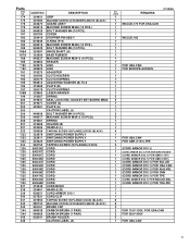
...305180 CLUTCH SCREW 305179 CLUTCH SPRING 962614 ADJUSTING WASHER (B) T0.5 319268 PLATE (B) 305179 CLUTCH SPRING 329863 LASER MARKER 319267 SPRING 319541 SEAL LOCK HEX. Parts ITEM NO. 174 175 176 179 180 181 182 ... (W/FLANGE) D4X20 (BLACK) 880734 MACHINE SCREW (W/WASHERS) M5X25 (BLACK) 945161 BRUSH CAP 999038 CARBON BRUSH (1 PAIR) 999065 CARBON BRUSH (1 PAIR) 938241 BRUSH HOLDER CAUTION LABEL (A) C12RSH NO. USED REMARKS 1 1 1 INCLUD.172 FOR USA.CAN 1 1 1 1 INCLUD.183 1 1 1 1 1 1 1 1 FOR USA.CAN 1 FOR EUROPE.AUS.NZL 1 1 1 1 1 1 1 2 2 1 1 1 3 3 ...
...305180 CLUTCH SCREW 305179 CLUTCH SPRING 962614 ADJUSTING WASHER (B) T0.5 319268 PLATE (B) 305179 CLUTCH SPRING 329863 LASER MARKER 319267 SPRING 319541 SEAL LOCK HEX. Parts ITEM NO. 174 175 176 179 180 181 182 ... (W/FLANGE) D4X20 (BLACK) 880734 MACHINE SCREW (W/WASHERS) M5X25 (BLACK) 945161 BRUSH CAP 999038 CARBON BRUSH (1 PAIR) 999065 CARBON BRUSH (1 PAIR) 938241 BRUSH HOLDER CAUTION LABEL (A) C12RSH NO. USED REMARKS 1 1 1 INCLUD.172 FOR USA.CAN 1 1 1 1 INCLUD.183 1 1 1 1 1 1 1 1 FOR USA.CAN 1 FOR EUROPE.AUS.NZL 1 1 1 1 1 1 1 2 2 1 1 1 3 3 ...


