User Guide
Page 11
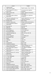
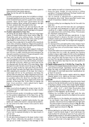
... Digital display (Only C12LSH) 6 mm Knob bolt (Optional accessory) Holder (Optional Accessory) Steel squar 6 mm Wing nut (Optional accessory) Height adjustment bolt 6 mm (Optional accessory) Base surface Stopper (Optional Accessory) 6 mm Knob bolt (Optional accessory) Sub fence (A) Knob (B) Screw holder 6 ...mm Knob bolt Vise shaft Slide seuring knob (B) Fence 6 mm Wing bolt Vise plate Knob Laser line Groove Bevel scale Miter scale Crown molding vise ass'y (Optional accessory)...
... Digital display (Only C12LSH) 6 mm Knob bolt (Optional accessory) Holder (Optional Accessory) Steel squar 6 mm Wing nut (Optional accessory) Height adjustment bolt 6 mm (Optional accessory) Base surface Stopper (Optional Accessory) 6 mm Knob bolt (Optional accessory) Sub fence (A) Knob (B) Screw holder 6 ...mm Knob bolt Vise shaft Slide seuring knob (B) Fence 6 mm Wing bolt Vise plate Knob Laser line Groove Bevel scale Miter scale Crown molding vise ass'y (Optional accessory)...

User Guide
Page 12
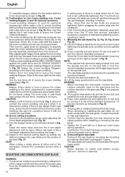
...; (B) fi Lukkovako fl Yläpinta ‡ 6 mm:n siipipultti (A) English Switch (For digital display) Marking (Pre-marked) Line Warning sign 5 mm Machine screw 6 mm Depth adjustment bolt Stopper holder Bottom line of the groove 5 mm Screw Poly-V-belt Pulley (A) Pulley (B) Locking groove Upper surface 6 mm Wing bolt (A) 11 Suomi ¥ Kytkin...
...; (B) fi Lukkovako fl Yläpinta ‡ 6 mm:n siipipultti (A) English Switch (For digital display) Marking (Pre-marked) Line Warning sign 5 mm Machine screw 6 mm Depth adjustment bolt Stopper holder Bottom line of the groove 5 mm Screw Poly-V-belt Pulley (A) Pulley (B) Locking groove Upper surface 6 mm Wing bolt (A) 11 Suomi ¥ Kytkin...
User Guide
Page 55
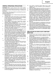
... Remove adjusting keys and wrenches. Watch what you are recommended when working efficiency reduced due to see that is damaged should only be spoiled and working outdoors. Have defective switches replaced by a qualified person. PRECAUTIONS ON USING SLIDE COMPOUND MITER SAW 1. ... instructions for better and safer performance. Disconnect tools. Check damaged parts. Do not use of loose materials e.g. Use only original HITACHI replacement parts. 10. pipes, radiators, ranges, refrigerators). 4. When using your tool at all these instructions before operating this handling...
... Remove adjusting keys and wrenches. Watch what you are recommended when working efficiency reduced due to see that is damaged should only be spoiled and working outdoors. Have defective switches replaced by a qualified person. PRECAUTIONS ON USING SLIDE COMPOUND MITER SAW 1. ... instructions for better and safer performance. Disconnect tools. Check damaged parts. Do not use of loose materials e.g. Use only original HITACHI replacement parts. 10. pipes, radiators, ranges, refrigerators). 4. When using your tool at all these instructions before operating this handling...

User Guide
Page 56
...; 710 mm C12LSH C12RSH 30 kg 29 kg Yes No Po Observe the maximum speed marked on . Do not use the saw blades which are damaged or deformed. 22. Replace the table insert when worn. 29. Do not use saw to a dust collecting device when sawing wood. 33. Connect the slide compound miter saw blade. 21. SPECIFICATIONS...
...; 710 mm C12LSH C12RSH 30 kg 29 kg Yes No Po Observe the maximum speed marked on . Do not use the saw blades which are damaged or deformed. 22. Replace the table insert when worn. 29. Do not use saw to a dust collecting device when sawing wood. 33. Connect the slide compound miter saw blade. 21. SPECIFICATIONS...

User Guide
Page 57
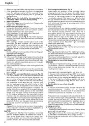
..., change the height where the bolt head and the hinge contacts, and adjust the lower limit position of a 8 mm depth adjustment bolt that the lower guard operates smoothly CAUTION ⅜ This slide compound miter saw head to cut the turntable or complete cutting cannot be disengaged. OPTIONAL ACCESSORIES (SOLD SEPARATELY) (1) Extension Holder and Stopper (2) Crown...
..., change the height where the bolt head and the hinge contacts, and adjust the lower limit position of a 8 mm depth adjustment bolt that the lower guard operates smoothly CAUTION ⅜ This slide compound miter saw head to cut the turntable or complete cutting cannot be disengaged. OPTIONAL ACCESSORIES (SOLD SEPARATELY) (1) Extension Holder and Stopper (2) Crown...
User Guide
Page 58
...cutting, use the sub fence (A). CAUTION After adjusting the table insert for right angle cutting, the table insert will be minimum. Aligning the ink line on the workpiece with the saw blade groove on the ink line. (2) Miter cutting and compound cutting (Miter cutting + bevel cutting) Never... subject your hand or anything else to retract the guard slightly. Adjust the base holder until its bottom surface contacts the ...
...cutting, use the sub fence (A). CAUTION After adjusting the table insert for right angle cutting, the table insert will be minimum. Aligning the ink line on the workpiece with the saw blade groove on the ink line. (2) Miter cutting and compound cutting (Miter cutting + bevel cutting) Never... subject your hand or anything else to retract the guard slightly. Adjust the base holder until its bottom surface contacts the ...
User Guide
Page 59
Never lift the lower guard while the saw blade appears. A switch lights up the laser marker. (On the C12RSH, only the laser marker switch.) CAUTION &#...Use of controls or adjustments or performance of the saw blade. Depending upon your eye is exposed directly to the laser marker (main body of factory shipment. When aligning the ink line, slide the workpiece little by ... If you press the digital display switch to ON without aligning the main unit to the retracted position. Adjust the positions of procedures other purposes. Digital display panel (for C12LSH) (Fig. 18 and Fig. 19...
Never lift the lower guard while the saw blade appears. A switch lights up the laser marker. (On the C12RSH, only the laser marker switch.) CAUTION &#...Use of controls or adjustments or performance of the saw blade. Depending upon your eye is exposed directly to the laser marker (main body of factory shipment. When aligning the ink line, slide the workpiece little by ... If you press the digital display switch to ON without aligning the main unit to the retracted position. Adjust the positions of procedures other purposes. Digital display panel (for C12LSH) (Fig. 18 and Fig. 19...

User Guide
Page 60
...handle to secure the turntable in width can result in use the main unit near equipment that the saw blade could cause damage to position. NOTE Turning knob (A) clockwise, allows fine adjustment of the turntable to 3 mm at maximum speed, slowly push down the handle while holding down ...the lever (A) and bring the saw blade in Fig. 21 the width of the saw blade is the width of the material to holder (A), then tighten the slide securing knob (A)/(B) (Fig....
...handle to secure the turntable in width can result in use the main unit near equipment that the saw blade could cause damage to position. NOTE Turning knob (A) clockwise, allows fine adjustment of the turntable to 3 mm at maximum speed, slowly push down the handle while holding down ...the lever (A) and bring the saw blade in Fig. 21 the width of the saw blade is the width of the material to holder (A), then tighten the slide securing knob (A)/(B) (Fig....

User Guide
Page 61
...long. Loosen the 6 mm wing nut. Make sure the end of Height Adjustment Bolt 6 mm does not protrude from the workpiece. Sometimes cutting cannot be performed by sliding the round portion of the saw blade. Checking the saw blade is secured on the right or left during the cutting operation. (1) As...when beveling. ⅜ Please do not grasp the holder. ⅜ There is clamped. CAUTION Always check that the gap between the lower edge of compound cutting (angle + bevel) by right bevel, turn the sub-fence (B) counterclockwise, and engage in 16 and 18 above. If the handle is ...
...long. Loosen the 6 mm wing nut. Make sure the end of Height Adjustment Bolt 6 mm does not protrude from the workpiece. Sometimes cutting cannot be performed by sliding the round portion of the saw blade. Checking the saw blade is secured on the right or left during the cutting operation. (1) As...when beveling. ⅜ Please do not grasp the holder. ⅜ There is clamped. CAUTION Always check that the gap between the lower edge of compound cutting (angle + bevel) by right bevel, turn the sub-fence (B) counterclockwise, and engage in 16 and 18 above. If the handle is ...
User Guide
Page 62
...turn the 10 mm bolt with 17 mm box wrench (standard accessory) while applying pressure on the saw blade and the rotation direction of the 6 mm depth adjustment bolt contacts the hinge.) (2) Adjust to secure the Crown molding Stoppers. (2) The crown molding vise (B) (Optional accessory) can be ...NOTE When cutting a single groove at either the left -hand threaded, loosen by adjusting the 6 mm depth adjustment bolt (Fig. 32). (1) Turn the stopper holder on either end of crown molding without tilting the saw blade spindle is locked when the spindle lock is lowered for cutting. The...
...turn the 10 mm bolt with 17 mm box wrench (standard accessory) while applying pressure on the saw blade and the rotation direction of the 6 mm depth adjustment bolt contacts the hinge.) (2) Adjust to secure the Crown molding Stoppers. (2) The crown molding vise (B) (Optional accessory) can be ...NOTE When cutting a single groove at either the left -hand threaded, loosen by adjusting the 6 mm depth adjustment bolt (Fig. 32). (1) Turn the stopper holder on either end of crown molding without tilting the saw blade spindle is locked when the spindle lock is lowered for cutting. The...

User Guide
Page 66
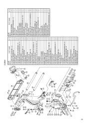
...SHAFT (A) 1 187 BASE RUBBER 1 188 MACHINE SCREW M5 × 12 1 189 SPACER 1 190 LINK 1 191 ADJUSTER 1 192 NYLON CLIP 1 193 CLUTCH SCREW 1 194 CLUTCH SPRING 1 195 ADJUSTING WASHER (B) T0.5 1 196 PLATE (B) 1 197 CLUTCH SPRING 1 198A LASER MARKER 1 199 SPRING 2 200 SEAL...STOPPER HOLDER (C) 1 161 STOPPER (C) 1 162 SET PIN (A) 1 163 MACHINE SCREW (W/WASHERS) M4 × 12 2 164 INDICATOR 2 165 CAUTION LABEL (B) 1 166 SLIDE PIPE (B) 1 167 SHAFT (D) 1 168 CORD (B) 1 169 CORD COVER 1 170 BOLT WASHER M4 1 171 MACHINE SCREW M4 × 16 1 173 HINGE (A) 1...
...SHAFT (A) 1 187 BASE RUBBER 1 188 MACHINE SCREW M5 × 12 1 189 SPACER 1 190 LINK 1 191 ADJUSTER 1 192 NYLON CLIP 1 193 CLUTCH SCREW 1 194 CLUTCH SPRING 1 195 ADJUSTING WASHER (B) T0.5 1 196 PLATE (B) 1 197 CLUTCH SPRING 1 198A LASER MARKER 1 199 SPRING 2 200 SEAL...STOPPER HOLDER (C) 1 161 STOPPER (C) 1 162 SET PIN (A) 1 163 MACHINE SCREW (W/WASHERS) M4 × 12 2 164 INDICATOR 2 165 CAUTION LABEL (B) 1 166 SLIDE PIPE (B) 1 167 SHAFT (D) 1 168 CORD (B) 1 169 CORD COVER 1 170 BOLT WASHER M4 1 171 MACHINE SCREW M4 × 16 1 173 HINGE (A) 1...
User Guide
Page 69
... SCREW M5 × 12 1 189 SPACER 1 190 LINK 1 191 ADJUSTER 1 193 CLUTCH SCREW 1 194 CLUTCH SPRING 1 195 ADJUSTING WASHER (B) T0.5 1 196 PLATE (B) 1 197 CLUTCH SPRING 1 198A LASER MARKER 1 199 SPRING 2 200 SEAL LOCK HEX. C12RSH ITEM NO. SOCKET SET SCREW M6 × 10 2 149 SLIDE PIPE (A) 1 150 SEAL LOCK HEX. BOLT M6 × 50...
... SCREW M5 × 12 1 189 SPACER 1 190 LINK 1 191 ADJUSTER 1 193 CLUTCH SCREW 1 194 CLUTCH SPRING 1 195 ADJUSTING WASHER (B) T0.5 1 196 PLATE (B) 1 197 CLUTCH SPRING 1 198A LASER MARKER 1 199 SPRING 2 200 SEAL LOCK HEX. C12RSH ITEM NO. SOCKET SET SCREW M6 × 10 2 149 SLIDE PIPE (A) 1 150 SEAL LOCK HEX. BOLT M6 × 50...
Parts List
Page 6
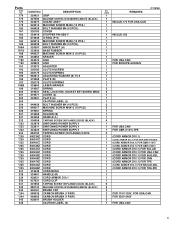
...MACHINE SCREW (W/WASHERS) M5X25 (BLACK) 945161 BRUSH CAP 999038 CARBON BRUSH (1 PAIR) 999065 CARBON BRUSH (1 PAIR) 938241 BRUSH HOLDER CAUTION LABEL (A) C12RSH NO. Parts ITEM NO. 174 175 176 179 180 181 182 183 184 185 186A 187A 188 189 *190 *190 191 193 194 195 196...PCS.) 324387 HINGE SHAFT (A) 323606 BASE RUBBER 949237 MACHINE SCREW M5X12 (10 PCS.) 303854 SPACER 324376 LINK 328522 LINK 319270 ADJUSTER 305180 CLUTCH SCREW 305179 CLUTCH SPRING 962614 ADJUSTING WASHER (B) T0.5 319268 PLATE (B) 305179 CLUTCH SPRING 329863 LASER MARKER 319267 SPRING 319541 SEAL LOCK HEX.
...MACHINE SCREW (W/WASHERS) M5X25 (BLACK) 945161 BRUSH CAP 999038 CARBON BRUSH (1 PAIR) 999065 CARBON BRUSH (1 PAIR) 938241 BRUSH HOLDER CAUTION LABEL (A) C12RSH NO. Parts ITEM NO. 174 175 176 179 180 181 182 183 184 185 186A 187A 188 189 *190 *190 191 193 194 195 196...PCS.) 324387 HINGE SHAFT (A) 323606 BASE RUBBER 949237 MACHINE SCREW M5X12 (10 PCS.) 303854 SPACER 324376 LINK 328522 LINK 319270 ADJUSTER 305180 CLUTCH SCREW 305179 CLUTCH SPRING 962614 ADJUSTING WASHER (B) T0.5 319268 PLATE (B) 305179 CLUTCH SPRING 329863 LASER MARKER 319267 SPRING 319541 SEAL LOCK HEX.


