Hitachi C12RSH Support Question
Hitachi C12RSH Support Question
Find answers below for this question about Hitachi C12RSH - 305mm Slide Compound Mitre Saw.Need a Hitachi C12RSH manual? We have 2 online manuals for this item!
Question posted by lanyalapunta on August 17th, 2011
Adjusting The Bevel 90 Degree Stop On A C12rsh / Bevel Out Of Alignment.
where can I find directions to the above question title
Current Answers
Related Hitachi C12RSH Manual Pages
User Guide - Page 11
...(Optional accessory) Holder (Optional Accessory) Steel squar 6 mm Wing nut (Optional accessory)
Height adjustment bolt 6 mm (Optional accessory) Base surface Stopper (Optional Accessory) 6 mm Knob bolt (Optional...Knob (B) Screw holder 6 mm Knob bolt Vise shaft Slide seuring knob (B) Fence 6 mm Wing bolt Vise plate Knob Laser line Groove Bevel scale Miter scale Crown molding vise ass'y (Optional ...
User Guide - Page 12

...; (B) fi Lukkovako fl Yläpinta ‡ 6 mm:n siipipultti (A)
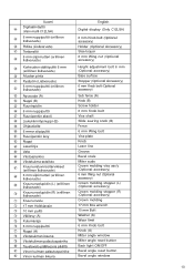
English Switch (For digital display) Marking (Pre-marked) Line Warning sign 5 mm Machine screw 6 mm Depth adjustment bolt Stopper holder Bottom line of the groove 5 mm Screw Poly-V-belt Pulley (A) Pulley (B) Locking groove Upper surface 6 mm Wing bolt (A)
11 Suomi ¥ Kytkin...
User Guide - Page 55
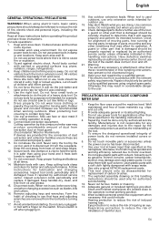
...tools should be stored in .
18. When tool is used only for which it frees both hands to the repair by authorized service
facility. PRECAUTIONS ON USING SLIDE COMPOUND
MITER SAW... for alignment of moving parts, free running of personal injury.
22. Also use tools for any... Keep cutting tools sharp and clean for lubrication and changing accessories. Remove adjusting keys and ...
User Guide - Page 56

... of foreign matter such as the laser radiation to your eyes, the inadvertent access to stop before servicing or adjusting tool. 38. Never operate the slide compound miter saw with the saw blades. Start cutting only after motor revolution reaches maximum speed. 36. Never use the saw with EN847-1. 24. Observe the maximum speed marked on . Use only...
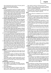
User Guide - Page 57

... adjust the lower limit position of the 8 mm depth adjustment bolt contacts the hinge. This may cause hazardous conditions (see that the lower guard operates smoothly CAUTION ⅜ This slide compound miter saw ...workpiece. When the power tool is prepared for the thickness of a 8 mm depth adjustment bolt that the machine is in right bevel angle cutting, adjust the lower limit position so...
User Guide - Page 58
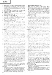
... in accordance with the saw blade groove on the guard and begin operations. (2) In the case of miter cutting or miter cutting plus bevel cutting: Loosen the 6 mm knob bolt, move during cutting 2. This power tool is cut on the ink line. (2) Miter cutting and compound cutting (Miter cutting + bevel cutting) Aligning the ink line on...
User Guide - Page 59
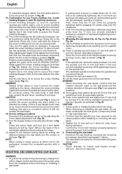
...;, 31.6° → 32.0°) then the positive stop still do as shown in Fig. 18. Position adjustment of the saw blade at least 0.2 second. otherwise, the cord may come off . ⅜ Exercise utmost caution in handling a switch trigger for the position adjustment of the saw blade, align the laser line with the laser line. ⅜...
User Guide - Page 60

... down gently and carefully. ⅜ In slide cutting, gently push the handle back (rearwards) in poor cutting precision. 17. Then, adjust the turntable until the indicator aligns with the laser line. (2) After turning on the digital display.
13. If the handle is raised while the saw blade has stopped. Then press down on the workpiece...
User Guide - Page 61

... right (as illustrated in Fig. 24, and change the direction of the clamp lever. (2) Adjust the bevel angle to the desired setting while watching the bevel angle scale and indicator, then secure the clamp lever. Compound cutting procedures Compound cutting can be accomplished because the saw blade stop completely before raising the handle from the holder. In case...
User Guide - Page 62
... angle. Lower the motor head, and turn the upper knob, as shown in Fig. 30. Mounting the saw blade and the rotation direction of the crown molding. When removing or installing the saw blade can be cut by adjusting the 6 mm depth adjustment bolt (Fig. 32). (1) Turn the stopper holder on the spindle lock. The...
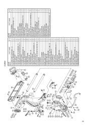
User Guide - Page 65
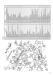
...69 70 71 72 73 74 75 76 77 78 79 80 81 82 83 85 87 88 89 90 91 92 93 94A 96 97 98 99 320 321 601 602 603 604 605 606 607 608 609 ...12 BOLT WASHER M4 INDICATOR SPACER (A) LOCK NUT M6 SPRING WASHER M6 GEAR (D) BEVEL SHAFT (B) SHAFT HOLDER (B) SHAFT HOLDER (A) BEVEL SHAFT (A) BOLT WASHER M6 NUT M6 KNOB (A) METAL D8 × 10 BEVEL GEAR SPRING WASHER M5 MACHINE SCREW M5 × 20 LEVER SHAFT COVER (B) ...
User Guide - Page 66

... CLUTCH SPRING
1
195 ADJUSTING WASHER (B) T0.5
1
196 PLATE (B)
1
197 CLUTCH SPRING
1
198A LASER MARKER
1
199 SPRING
2
200 SEAL LOCK HEX. PART NAME
Q'TY
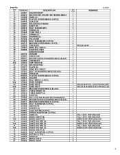
131 MACHINE SCREW M4 × 12
1
132 BOLT WASHER M4
1
133 NYLON CLIP
1
134 SUPPORT
2
135 HEX. SOCKET HD. SOCKET SET SCREW M6 × 10 2
149 SLIDE PIPE (A)
1
150...
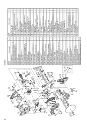
User Guide - Page 68
...M6
3
78 NUT M6
1
79 KNOB (A)
1
80 METAL D8 × 10
2
81 BEVEL GEAR
2
82 SPRING WASHER M5
4
83 MACHINE SCREW M5 × 20
4
85 LEVER SHAFT
1
87 COVER (B)
1
88 SHAFT (C)
1
89 LEVER
1
90 SPRING (D)
1
91 SHAFT (A)
1
92 SIDE HANDLE
1
93 PLATE (A)
1
94A SUB ... (B)
1
64 SEAL LOCK HEX. SOCKET SET SCREW M8 × 16 1
19 GEAR (A)
1
20 FLAT HD. 67
C12RSH
ITEM NO.
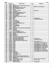
User Guide - Page 69
C12RSH
ITEM NO. SOCKET SET SCREW M6 × 10 2
149 SLIDE PIPE (A)
1
150 SEAL LOCK HEX. BOLT M6 × 50
2
160 STOPPER HOLDER (C)
1
161 STOPPER (C)
1
162 SET PIN (A)
1
163 MACHINE SCREW (W/WASHERS) M4 × 12 2
164 INDICATOR
2
165 CAUTION LABEL (B)
1
166 SLIDE...
1
190 LINK
1
191 ADJUSTER
1
193 CLUTCH SCREW
1
194 CLUTCH SPRING
1
195 ADJUSTING WASHER (B) T0.5
1
196...
User Guide - Page 70
... 2
345 LEVER SPRING
1
501 BOX WRENCH 17MM
1
502 DUST BAG
1
PART NAME
Q'TY
284 BOLT (A) M10
1
285B WASHER (B)
1
286 TCT SAW BLADE 305MM-D25.4 HOLE-NT60 1
287 WASHER (A)
1
288 FLAT HD. 69
C12RSH
ITEM NO. PART NAME
231 HANDLE (L)
232 TAPPING SCREW (W/FLANGE) D5 × 25
233 SWITCHING POWER SUPPLY
234 TAPPING SCREW...
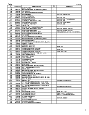
Parts List - Page 4
... PCS.) INDICATOR SPACER (A) LOCK NUT M6 (10 PCS.) SPRING WASHER M6 (10 PCS.)
324407 GEAR (D) 324405 BEVEL SHAFT (B)
336255 324404 336257 324403 336258 324408 949432 949556
BEVEL SHAFT (C) SHAFT HOLDER (B) SHAFT HOLDER (B) SHAFT HOLDER (A) SHAFT HOLDER (A) BEVEL SHAFT (A) BOLT WASHER M6 (10 PCS.) NUT M6 (10 PCS.)
324409 950817 324406
KNOB (A) METAL D8X10...
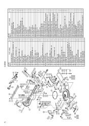
Parts List - Page 5

...WASHER M8 (10 PCS.)
949782 HEX. Parts
ITEM NO.
82 83 85 86 87 88 89 90 91A 92 93 94A 96 98 99 100 101 102 103 104 105 106 107 131 132 *... PIN (A)
935196 MACHINE SCREW (W/WASHERS) M4X12 (BLACK)
321329 INDICATOR
CAUTION LABEL (B)
324466 SLIDE PIPE (B)
305558 TAPPING SCREW (W/FLANGE) D5X25 (BLACK) 324467 HINGE (A)
C12RSH
NO. SOCKET SET SCREW M6X10 324465 SLIDE PIPE (A)
877839 SEAL LOCK HEX.
Parts List - Page 6
...SPACER
324376 LINK
328522 LINK
319270 ADJUSTER
305180 CLUTCH SCREW
305179 CLUTCH SPRING
962614 ADJUSTING WASHER (B) T0.5
319268 PLATE ...SCREW (W/WASHERS) M5X25 (BLACK)
945161 BRUSH CAP
999038 CARBON BRUSH (1 PAIR)
999065 CARBON BRUSH (1 PAIR)
938241 BRUSH HOLDER
CAUTION LABEL (A)
C12RSH
NO. USED
REMARKS
1
1
1 INCLUD.172 FOR USA.CAN
1
1
1
1 INCLUD.183
1
1
1
1
1
1
1
1 FOR...
Parts List - Page 7
...SCREW (W/WASHERS) M4X12 (BLACK) BOLT (A) M10 WASHER (B) TCT SAW BLADE 305MM-D30 HOLE-NT60 TCT SAW BLADE 305MM-D25.4 HOLE-NT60 TCT SAW BLADE 305MM-D25.4 HOLE-NT90 WASHER (A) FLAT HD. Parts
ITEM NO.
247... COVER RETURN SPRING (B) SPINDLE ASS'Y BALL BEARING 6003DD BEARING HOLDER BALL BEARING 608VVC2PS2L
C12RSH
NO. SOCKET SET SCREW M5X8 HOUSING ASS'Y BRUSH TERMINAL STATOR ASS'Y 110V STATOR ASS...
Parts List - Page 8

... (W/FLANGE) D4X16 (BLACK) LEVER SPRING MACHINE SCREW (W/WASHERS) M5X16 (BLACK) FERRITE CORE WASHER (D)
328520
336342 336343
WASHER (C) CAUTION LABEL (H) MACHINE SCREW (W/WASHERS) M5X10 (BLACK) GUARD (C)
C12RSH
NO. DESCRIPTION
949241 949454 321364 312492 324440 948919
MACHINE SCREW M5X20 (10 PCS.) SPRING WASHER M5 (10 PCS.) DUST GUIDE GUIDE HOLDER PINION ASS'Y FEATHER...
Similar Questions

Dial Is Set To 90 Degrees But Wont Bend Past 65-70 Degree Help!
So I tried to bend and i had the dial set to 90 degrees but after it was finished the bar was only b...
So I tried to bend and i had the dial set to 90 degrees but after it was finished the bar was only b...
(Posted by kaylamcconnell17 9 years ago)

C12rsh Laser Marker
Hi the laser has stopped working on my saw and wandering if it is common fault or a one off and if s...
Hi the laser has stopped working on my saw and wandering if it is common fault or a one off and if s...
(Posted by Woodyrally 9 years ago)
How To Adjust Cut Depth Hitachi 10 Compound Miter Saw Manual
(Posted by dbrag 9 years ago)

Bevel Lock Slips
When I move the blade to the right for beveling the locking mechanism can't keep it in place after a...
When I move the blade to the right for beveling the locking mechanism can't keep it in place after a...
(Posted by rwang1 12 years ago)

Where Can I Get A Free Manual On The Hitachi C12rsh 12' Slide Compound Miter Saw
(Posted by kathy86883 14 years ago)