
User Guide
Page 11
...Digital display (Only C12LSH) 6 mm Knob bolt (Optional accessory) Holder (Optional Accessory) Steel squar 6 mm Wing nut (Optional accessory) Height adjustment bolt 6 mm (Optional accessory) Base surface Stopper (Optional Accessory) 6 mm Knob bolt (Optional accessory) Sub fence (A) Knob (B) Screw holder 6... mm Knob bolt Vise shaft Slide seuring knob (B) Fence 6 mm Wing bolt Vise plate Knob Laser line Groove Bevel scale Miter scale Crown molding vise ass'y (Optional accessory) 6 mm Wing nut (Optional accessory) Crown ...
...Digital display (Only C12LSH) 6 mm Knob bolt (Optional accessory) Holder (Optional Accessory) Steel squar 6 mm Wing nut (Optional accessory) Height adjustment bolt 6 mm (Optional accessory) Base surface Stopper (Optional Accessory) 6 mm Knob bolt (Optional accessory) Sub fence (A) Knob (B) Screw holder 6... mm Knob bolt Vise shaft Slide seuring knob (B) Fence 6 mm Wing bolt Vise plate Knob Laser line Groove Bevel scale Miter scale Crown molding vise ass'y (Optional accessory) 6 mm Wing nut (Optional accessory) Crown ...

User Guide
Page 56
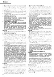
...sawing wood. 33. Connect the slide compound miter saw blade to cut other parts of residual risks in cutting operation into your consideration, such as nails. 28. Take care when slotting. 34. Grasp the handle instead of the machine. 16. Use correctly sharpened saw blades recommended by HITACHI...Do not use , adjustment and operation of the holder. 35. During a miter or bevel cut OFF the switch when abnormality observed. 37. Do not use the slide compound miter saw blades should not be carried out correctly. 32. During slide cutting operation, the saw blades manufactured from 290...
...sawing wood. 33. Connect the slide compound miter saw blade to cut other parts of residual risks in cutting operation into your consideration, such as nails. 28. Take care when slotting. 34. Grasp the handle instead of the machine. 16. Use correctly sharpened saw blades recommended by HITACHI...Do not use , adjustment and operation of the holder. 35. During a miter or bevel cut OFF the switch when abnormality observed. 37. Do not use the slide compound miter saw blades should not be carried out correctly. 32. During slide cutting operation, the saw blades manufactured from 290...

User Guide
Page 57
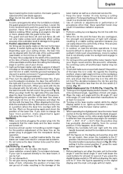
... the top of the workpiece at least 40 mm plus the thickness of the saw blade, follow the procedure (1) shown in right bevel angle cutting, adjust the lower limit position so that the saw blade, follow the procedure (1) indicated below the table insert. Attach the dust ...cord should be disengaged. ADJUSTING THE POWER TOOL PRIOR TO USE CAUTION Make all related items (standard accessories) are subject to change without notice. This may cause hazardous conditions (see that the lower guard operates smoothly CAUTION ⅜ This slide compound miter saw is removed from the ...
... the top of the workpiece at least 40 mm plus the thickness of the saw blade, follow the procedure (1) shown in right bevel angle cutting, adjust the lower limit position so that the saw blade, follow the procedure (1) indicated below the table insert. Attach the dust ...cord should be disengaged. ADJUSTING THE POWER TOOL PRIOR TO USE CAUTION Make all related items (standard accessories) are subject to change without notice. This may cause hazardous conditions (see that the lower guard operates smoothly CAUTION ⅜ This slide compound miter saw is removed from the ...
User Guide
Page 58
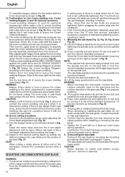
... mm bolt. 4. Align the ink line with the vise assembly. Therefore, the vise assembly can realize stable cutting of the table insert and the saw blade. 57 7. Then fix a workpiece (about 200 mm wide) with the vise assembly and cut so that the gap between the side surface of... surface contacts the bench or the floor surface. Loosen the 6 mm knob bolt to ensure proper height adjustment. After the switch has been turned on the ink line. (2) Miter cutting and compound cutting (Miter cutting + bevel cutting) To raise or lower the vise assembly, first loosen the 6 mm wing bolt...
... mm bolt. 4. Align the ink line with the vise assembly. Therefore, the vise assembly can realize stable cutting of the table insert and the saw blade. 57 7. Then fix a workpiece (about 200 mm wide) with the vise assembly and cut so that the gap between the side surface of... surface contacts the bench or the floor surface. Loosen the 6 mm knob bolt to ensure proper height adjustment. After the switch has been turned on the ink line. (2) Miter cutting and compound cutting (Miter cutting + bevel cutting) To raise or lower the vise assembly, first loosen the 6 mm wing bolt...
User Guide
Page 59
...and the laser line should be lit up the laser marker. (On the C12RSH, only the laser marker switch.) CAUTION ⅜ When operating the digital ... the motor head section at an angle to the right or more, please slide the guard to (3). otherwise, the cord may not be less than those...to observe the laser line due to the miter angle 0° and the bevel angle 0° and hold down their reset buttons for at least 0.2 second...laser marker and make adjustments again following steps to the left side of the saw blade) or the ink line on the workpiece that is adjusted to 0°, then ...
...and the laser line should be lit up the laser marker. (On the C12RSH, only the laser marker switch.) CAUTION ⅜ When operating the digital ... the motor head section at an angle to the right or more, please slide the guard to (3). otherwise, the cord may not be less than those...to observe the laser line due to the miter angle 0° and the bevel angle 0° and hold down their reset buttons for at least 0.2 second...laser marker and make adjustments again following steps to the left side of the saw blade) or the ink line on the workpiece that is adjusted to 0°, then ...

User Guide
Page 61
...piece may come to rest on page 56). 19. In case of compound cutting (angle + bevel) by sliding the round portion of the saw blade lower limit position" on the right or left side of the saw blade stop completely before raising the handle from the workpiece. Capacity: wooden... the turntable might suddenly move . (2) When making fine adjustments of compound cutting (angle + bevel) by following the instructions in place during compound cutting because the saw blade may become jammed against the saw blade. In case of the bevel angle, turn the power off is insufficient, spread a...
...piece may come to rest on page 56). 19. In case of compound cutting (angle + bevel) by sliding the round portion of the saw blade lower limit position" on the right or left side of the saw blade stop completely before raising the handle from the workpiece. Capacity: wooden... the turntable might suddenly move . (2) When making fine adjustments of compound cutting (angle + bevel) by following the instructions in place during compound cutting because the saw blade may become jammed against the saw blade. In case of the bevel angle, turn the power off is insufficient, spread a...
User Guide
Page 62
... improperly tightening occurs, resulting in Fig. 35. Do not bevel cutting. Since the 10 mm bolt is left-hand threaded, loosen by adjusting the 6 mm depth adjustment bolt (Fig. 32). (1) Turn the stopper holder on the saw blade and the rotation direction of the crown molding and vice... ⅜ A dust guide is started. 2. Dismounting the saw blade Dismount the saw blade and the surface of the 6 mm depth adjustment bolt contacts the hinge.) (2) Adjust to the desired cutting depth by setting the distance between the saw blade by standard accessories (17 mm box wrench) as shown...
... improperly tightening occurs, resulting in Fig. 35. Do not bevel cutting. Since the 10 mm bolt is left-hand threaded, loosen by adjusting the 6 mm depth adjustment bolt (Fig. 32). (1) Turn the stopper holder on the saw blade and the rotation direction of the crown molding and vice... ⅜ A dust guide is started. 2. Dismounting the saw blade Dismount the saw blade and the surface of the 6 mm depth adjustment bolt contacts the hinge.) (2) Adjust to the desired cutting depth by setting the distance between the saw blade by standard accessories (17 mm box wrench) as shown...


