User Guide
Page 55
...if the cutting operation is off . 21. Never carry the tool by the cord or yank it to disconnect it on this compound miter saw to the user. It is damaged should be done only by this handling instructions should be used only for better and safer performance... handling instructions, may present a risk of personal injury. 22. PRECAUTIONS ON USING SLIDE COMPOUND MITER SAW 1. Keep the floor area around the machine level. Do not wipe plastic parts with such solvent. Use only original HITACHI replacement parts. 10. The exploded assembly drawing on and off when plugging in. ...
...if the cutting operation is off . 21. Never carry the tool by the cord or yank it to disconnect it on this compound miter saw to the user. It is damaged should be done only by this handling instructions should be used only for better and safer performance... handling instructions, may present a risk of personal injury. 22. PRECAUTIONS ON USING SLIDE COMPOUND MITER SAW 1. Keep the floor area around the machine level. Do not wipe plastic parts with such solvent. Use only original HITACHI replacement parts. 10. The exploded assembly drawing on and off when plugging in. ...

User Guide
Page 56
...176; - 31° (110 V, 230 V) 1520 W 4000 min-1 595 mm × 930 mm × 710 mm C12LSH C12RSH 30 kg 29 kg Yes No Po Do not use the slide compound miter saw must be carried out correctly. 32. Start cutting only after motor revolution reaches maximum speed. 36. During...(Right) 45° + Miter (Right) 45° Saw Blade Dimensions (oD × iD × Thickness) Miter Cutting Angle Bevel Cutting Angle Compound Cutting Angle Bevel (Left) 0° - 45° Bevel (Right) 0° - 45° Voltage (by HITACHI. Replace the table insert when worn. 29. Observe the ...
...176; - 31° (110 V, 230 V) 1520 W 4000 min-1 595 mm × 930 mm × 710 mm C12LSH C12RSH 30 kg 29 kg Yes No Po Do not use the slide compound miter saw must be carried out correctly. 32. Start cutting only after motor revolution reaches maximum speed. 36. During...(Right) 45° + Miter (Right) 45° Saw Blade Dimensions (oD × iD × Thickness) Miter Cutting Angle Bevel Cutting Angle Compound Cutting Angle Bevel (Left) 0° - 45° Bevel (Right) 0° - 45° Voltage (by HITACHI. Replace the table insert when worn. 29. Observe the ...

User Guide
Page 57
...accessories) are subject to make adjustments so that the lower guard operates smoothly CAUTION ⅜ This slide compound miter saw is turning. 56 English STANDARD ACCESSORIES (1) 305 mm TCT Saw blade (mounted on the product nameplate. 2. OPTIONAL ACCESSORIES (SOLD SEPARATELY) (1) Extension Holder and Stopper...of a 8 mm depth adjustment bolt that the machine is being operated. ⅜ Never place your thumb. (1) When you replace a saw blade with a new one, adjust the lower limit position so that it will start operating immediately, inviting serious accident. 3. The extension cord...
...accessories) are subject to make adjustments so that the lower guard operates smoothly CAUTION ⅜ This slide compound miter saw is turning. 56 English STANDARD ACCESSORIES (1) 305 mm TCT Saw blade (mounted on the product nameplate. 2. OPTIONAL ACCESSORIES (SOLD SEPARATELY) (1) Extension Holder and Stopper...of a 8 mm depth adjustment bolt that the machine is being operated. ⅜ Never place your thumb. (1) When you replace a saw blade with a new one, adjust the lower limit position so that it will start operating immediately, inviting serious accident. 3. The extension cord...
User Guide
Page 58
...the 6 mm wing bolt (A) and move during cutting 2. When shipping the tool from the factory, the table inserts are installed on and the saw blade may contact the sub fence (A), resulting in an injury. Remove the workpiece and securely tighten the 5 mm center machine screw. Unless it ... tighten the 6 mm machine screws of both ends. Switch operation Pulling the trigger turns the switch on the ink line. (2) Miter cutting and compound cutting (Miter cutting + bevel cutting) Releasing the trigger turns the switch off. 3. Therefore, the vise assembly can realize stable cutting of the ...
...the 6 mm wing bolt (A) and move during cutting 2. When shipping the tool from the factory, the table inserts are installed on and the saw blade may contact the sub fence (A), resulting in an injury. Remove the workpiece and securely tighten the 5 mm center machine screw. Unless it ... tighten the 6 mm machine screws of both ends. Switch operation Pulling the trigger turns the switch on the ink line. (2) Miter cutting and compound cutting (Miter cutting + bevel cutting) Releasing the trigger turns the switch off. 3. Therefore, the vise assembly can realize stable cutting of the ...
User Guide
Page 59
.... CAUTION (Fig. 13 and Fig. 14) ⅜ Laser radiation - If you align it ; Depending upon your choice. (1) Light up the laser marker. (On the C12RSH, only the laser marker switch.) CAUTION ⅜ When operating the digital panel, have the motor head section at an angle to the right or more..., please slide the guard to the 0° position. Adjust the positions of the saw blade) or the ink line on the digital display switch shows 0° for the position adjustment of lines. If...
.... CAUTION (Fig. 13 and Fig. 14) ⅜ Laser radiation - If you align it ; Depending upon your choice. (1) Light up the laser marker. (On the C12RSH, only the laser marker switch.) CAUTION ⅜ When operating the digital panel, have the motor head section at an angle to the right or more..., please slide the guard to the 0° position. Adjust the positions of the saw blade) or the ink line on the digital display switch shows 0° for the position adjustment of lines. If...

User Guide
Page 60
...in width. (2) Workpieces up to 120 mm in a single, smooth operation. If a laser marker is lowered. 16. Forward slide cutting (toward the operator) is very dangerous because the saw blade could cause damage to the side handle when the motor head is used for cutting, refer to 107 mm high... and 312 mm wide: Loosen the slide securing knob (A) (Fig. 2), grip the handle and slide the saw blade causing fragments to cut a workpiece at maximum speed, slowly push down the handle while holding down to the left...
...in width. (2) Workpieces up to 120 mm in a single, smooth operation. If a laser marker is lowered. 16. Forward slide cutting (toward the operator) is very dangerous because the saw blade could cause damage to the side handle when the motor head is used for cutting, refer to 107 mm high... and 312 mm wide: Loosen the slide securing knob (A) (Fig. 2), grip the handle and slide the saw blade causing fragments to cut a workpiece at maximum speed, slowly push down the handle while holding down to the left...

User Guide
Page 61
... left (as seen from the holder. It is secured on the left or right side of the blade, the short cut it by sliding the round portion of the saw blade. Capacity: wooden material (W × H × L) 300 mm × 45 mm × 1300 mm, or 180 mm × 25 mm...mm wing nut. Installing the holders ... (Optional accessory) The holders help keep longer workpieces stable and in place during compound cutting because the saw blade may become jammed against the saw blade stop completely before raising the handle from the workpiece. CAUTION Always check that the clamp lever is secured and ...
... left (as seen from the holder. It is secured on the left or right side of the blade, the short cut it by sliding the round portion of the saw blade. Capacity: wooden material (W × H × L) 300 mm × 45 mm × 1300 mm, or 180 mm × 25 mm...mm wing nut. Installing the holders ... (Optional accessory) The holders help keep longer workpieces stable and in place during compound cutting because the saw blade may become jammed against the saw blade stop completely before raising the handle from the workpiece. CAUTION Always check that the clamp lever is secured and ...
User Guide
Page 62
...vise, Crown molding Stopper (L) and (R) (Optional accessory) (1) Crown molding Stopper (L) and (R) (optional accessories) allow easier cuts of crown molding without tilting the saw blade. 25. After adjusting the height, firmly tighten the 6 mm wing bolt; then turn the upper knob, as indicated in Fig. 35. Tighten the ... of the crown molding and vice can be pressed down. NOTE If the spindle lock cannot be removed after installing or removing the saw blade and the rotation direction of the crown molding. Then turn the upper knob, as shown in paragraph 1 above. Groove cutting ...
...vise, Crown molding Stopper (L) and (R) (Optional accessory) (1) Crown molding Stopper (L) and (R) (optional accessories) allow easier cuts of crown molding without tilting the saw blade. 25. After adjusting the height, firmly tighten the 6 mm wing bolt; then turn the upper knob, as indicated in Fig. 35. Tighten the ... of the crown molding and vice can be pressed down. NOTE If the spindle lock cannot be removed after installing or removing the saw blade and the rotation direction of the crown molding. Then turn the upper knob, as shown in paragraph 1 above. Groove cutting ...

User Guide
Page 63
...to the hand pressure applied by the tool handle tends to increase, making it unsafe to assure that the following sliding surfaces once a month to Hitachi Authorised Service Center. Inspecting the mounting screws Regularly inspect all 13 teeth of the belt to incorporate the latest ... In addition, always keep carbon brushes clean and ensure that they slide freely within the brush holders. 4. Replacement of Poly-V-Belt The power of the motor is transmitted to the saw blade immediately upon the first sign of Hitachi Power Tools must be observed. Service parts list A : Item No...
...to the hand pressure applied by the tool handle tends to increase, making it unsafe to assure that the following sliding surfaces once a month to Hitachi Authorised Service Center. Inspecting the mounting screws Regularly inspect all 13 teeth of the belt to incorporate the latest ... In addition, always keep carbon brushes clean and ensure that they slide freely within the brush holders. 4. Replacement of Poly-V-Belt The power of the motor is transmitted to the saw blade immediately upon the first sign of Hitachi Power Tools must be observed. Service parts list A : Item No...

User Guide
Page 67
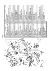
... END PLATE 255 HEX. HD. PART NAME Q'TY 282 WASHER M6 1 283 MACHINE SCREW (W/WASHERS) M4 × 12 1 284 BOLT (A) M10 1 285B WASHER (B) 1 286 TCT SAW BLADE 305MM-D25.4 HOLE-NT60 1 287 WASHER (A) 1 288 FLAT HD. SCREW M4 × 10 2 289 COVER 1 290 PROTECTIVE COVER 1 291 RETURN SPRING (A) 1 292 SPINDLE ASS'Y 1 293...
... END PLATE 255 HEX. HD. PART NAME Q'TY 282 WASHER M6 1 283 MACHINE SCREW (W/WASHERS) M4 × 12 1 284 BOLT (A) M10 1 285B WASHER (B) 1 286 TCT SAW BLADE 305MM-D25.4 HOLE-NT60 1 287 WASHER (A) 1 288 FLAT HD. SCREW M4 × 10 2 289 COVER 1 290 PROTECTIVE COVER 1 291 RETURN SPRING (A) 1 292 SPINDLE ASS'Y 1 293...
User Guide
Page 70
PART NAME Q'TY 284 BOLT (A) M10 1 285B WASHER (B) 1 286 TCT SAW BLADE 305MM-D25.4 HOLE-NT60 1 287 WASHER (A) 1 288 FLAT HD. SCREW M4 × 10 2 289 COVER 1 290 PROTECTIVE COVER 1 291 RETURN SPRING 1 292 SPINDLE ASS'Y 1 293 BALL ...(W/WASHERS)M4 × 16 1 343 LEVER COVER 1 344 TAPPING SCREW(W/FLANGE)D4 × 16 2 345 LEVER SPRING 1 501 BOX WRENCH 17MM 1 502 DUST BAG 1 69 C12RSH ITEM NO.
PART NAME Q'TY 284 BOLT (A) M10 1 285B WASHER (B) 1 286 TCT SAW BLADE 305MM-D25.4 HOLE-NT60 1 287 WASHER (A) 1 288 FLAT HD. SCREW M4 × 10 2 289 COVER 1 290 PROTECTIVE COVER 1 291 RETURN SPRING 1 292 SPINDLE ASS'Y 1 293 BALL ...(W/WASHERS)M4 × 16 1 343 LEVER COVER 1 344 TAPPING SCREW(W/FLANGE)D4 × 16 2 345 LEVER SPRING 1 501 BOX WRENCH 17MM 1 502 DUST BAG 1 69 C12RSH ITEM NO.
Parts List
Page 1
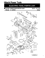
ELECTRIC TOOL PARTS LIST SLIDE COMPOUND MITER SAW Model C 12RSH 2015 • 12 • 22 (E2a) Allen R oell 1
ELECTRIC TOOL PARTS LIST SLIDE COMPOUND MITER SAW Model C 12RSH 2015 • 12 • 22 (E2a) Allen R oell 1
Parts List
Page 7
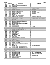
...6003DD 324439 608VVM PROTECTIVE COVER PROTECTIVE COVER PROTECTIVE COVER RETURN SPRING (B) SPINDLE ASS'Y BALL BEARING 6003DD BEARING HOLDER BALL BEARING 608VVC2PS2L C12RSH NO. TAPPING SCREW D5X50 ARMATURE ASS'Y 220V-230V ARMATURE ASS'Y 240V ARMATURE ASS'Y 110V-120V BALL BEARING 6000VVCMPS2L FAN GUIDE 6201VV...10 PCS.) WASHER M6 (10 PCS.) MACHINE SCREW (W/WASHERS) M4X12 (BLACK) BOLT (A) M10 WASHER (B) TCT SAW BLADE 305MM-D30 HOLE-NT60 TCT SAW BLADE 305MM-D25.4 HOLE-NT60 TCT SAW BLADE 305MM-D25.4 HOLE-NT90 WASHER (A) FLAT HD. SOCKET SET SCREW M5X8 HOUSING ASS'Y BRUSH TERMINAL STATOR ASS'Y 110V...
...6003DD 324439 608VVM PROTECTIVE COVER PROTECTIVE COVER PROTECTIVE COVER RETURN SPRING (B) SPINDLE ASS'Y BALL BEARING 6003DD BEARING HOLDER BALL BEARING 608VVC2PS2L C12RSH NO. TAPPING SCREW D5X50 ARMATURE ASS'Y 220V-230V ARMATURE ASS'Y 240V ARMATURE ASS'Y 110V-120V BALL BEARING 6000VVCMPS2L FAN GUIDE 6201VV...10 PCS.) WASHER M6 (10 PCS.) MACHINE SCREW (W/WASHERS) M4X12 (BLACK) BOLT (A) M10 WASHER (B) TCT SAW BLADE 305MM-D30 HOLE-NT60 TCT SAW BLADE 305MM-D25.4 HOLE-NT60 TCT SAW BLADE 305MM-D25.4 HOLE-NT90 WASHER (A) FLAT HD. SOCKET SET SCREW M5X8 HOUSING ASS'Y BRUSH TERMINAL STATOR ASS'Y 110V...
Parts List
Page 9
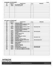
USED 501 985051 BOX WRENCH 17MM 1 502A 322955 DUST BAG (BLACK) 1 REMARKS C12RSH OPTIONAL ACCESSORIES ITEM NO. CODE NO. CODE NO. USED REMARKS 1 1 1 1 1 INCLUD.601-604 2 1 1 1 1 INCLUD.606-609 2 2 2 2 2 2 INCLUD.611-615 1 1 1 INCLUD.606.616-618 1 1 1 1 1 1 1 INCLUD.620-... RUBBER 623 306985 WASHER (H) 624 SCREW HOLDER (B) 625 321551 KNOB BOLT M10X54 626 321388 VISE (B) ASS'Y 627 321434 CROWN MOLDING VISE ASS'Y 628 726100 TCT SAW BLADE 305MM-D25.4 HOLE-NT60 629 725101 TCT SAW BLADE 305MM-D25.4 HOLE-NT90 NO. DESCRIPTION NO.
USED 501 985051 BOX WRENCH 17MM 1 502A 322955 DUST BAG (BLACK) 1 REMARKS C12RSH OPTIONAL ACCESSORIES ITEM NO. CODE NO. CODE NO. USED REMARKS 1 1 1 1 1 INCLUD.601-604 2 1 1 1 1 INCLUD.606-609 2 2 2 2 2 2 INCLUD.611-615 1 1 1 INCLUD.606.616-618 1 1 1 1 1 1 1 INCLUD.620-... RUBBER 623 306985 WASHER (H) 624 SCREW HOLDER (B) 625 321551 KNOB BOLT M10X54 626 321388 VISE (B) ASS'Y 627 321434 CROWN MOLDING VISE ASS'Y 628 726100 TCT SAW BLADE 305MM-D25.4 HOLE-NT60 629 725101 TCT SAW BLADE 305MM-D25.4 HOLE-NT90 NO. DESCRIPTION NO.


