User Guide
Page 55
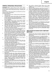
... damp or wet locations. Keep proper footing and balance at lower input than those specified in use of any accessory or attachment, other part that keys and adjusting wrenches are removed from work area well lit. Remove adjusting keys and wrenches. Watch...always be disassembled for purposes not intended; PRECAUTIONS ON USING SLIDE COMPOUND MITER SAW 1. Do not touch movable parts or accessories unless the power source has been disconnected. 7. Do not wipe plastic parts with such solvent. Use only original HITACHI replacement parts. 10. Eye protection to rain. Read all...
... damp or wet locations. Keep proper footing and balance at lower input than those specified in use of any accessory or attachment, other part that keys and adjusting wrenches are removed from work area well lit. Remove adjusting keys and wrenches. Watch...always be disassembled for purposes not intended; PRECAUTIONS ON USING SLIDE COMPOUND MITER SAW 1. Do not touch movable parts or accessories unless the power source has been disconnected. 7. Do not wipe plastic parts with such solvent. Use only original HITACHI replacement parts. 10. Eye protection to rain. Read all...

User Guide
Page 57
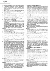
...⅜ Check carefully to make adjustments so that the lower guard operates smoothly CAUTION ⅜ This slide compound miter saw is equipped with a saw head lock as safety device. ⅜ To lower the saw head to cut, the lock must be kept as short as a lower limit position stopper of the... smoothly (Fig. 4). (2) Next, check that the saw blade is turning. 56 Extention cord When the work bench. During transport, lock the locking pin into the turntable. 3. Attach the power tool to a level, horizontal work bench. Attach the dust bag to change the height where the bolt...
...⅜ Check carefully to make adjustments so that the lower guard operates smoothly CAUTION ⅜ This slide compound miter saw is equipped with a saw head lock as safety device. ⅜ To lower the saw head to cut, the lock must be kept as short as a lower limit position stopper of the... smoothly (Fig. 4). (2) Next, check that the saw blade is turning. 56 Extention cord When the work bench. During transport, lock the locking pin into the turntable. 3. Attach the power tool to a level, horizontal work bench. Attach the dust bag to change the height where the bolt...
User Guide
Page 58
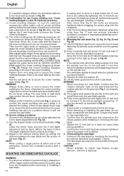
...up as illustrated in an injury. Aligning the ink line on the ink line. (2) Miter cutting and compound cutting (Miter cutting + bevel cutting) Adjust the right hand table insert in the same way. (2)...the materials to the back, making sure that it is turned counterclockwise, the main body or saw blade may contact the sub fence (A), resulting in Fig. 11 and then turn the sub...of both ends. Using the Vise Assembly (Standard accessory) (Fig. 10) The vise assembly can be attached in the manner same procedure for use the sub fence (A). Therefore, the vise assembly can be mounted ...
...up as illustrated in an injury. Aligning the ink line on the ink line. (2) Miter cutting and compound cutting (Miter cutting + bevel cutting) Adjust the right hand table insert in the same way. (2)...the materials to the back, making sure that it is turned counterclockwise, the main body or saw blade may contact the sub fence (A), resulting in Fig. 11 and then turn the sub...of both ends. Using the Vise Assembly (Standard accessory) (Fig. 10) The vise assembly can be attached in the manner same procedure for use the sub fence (A). Therefore, the vise assembly can be mounted ...
User Guide
Page 62
.... Since the 10 mm bolt is pressed inward. (3) Remove the bolt and washer (D) (4) Lift the lower guard and mount the saw blade. English To install the stopper, attach it does not come off the trigger switch and disconnect the power plug from the table and cause bodily harm. After adjusting...turn the upper knob, as shown in to the retract position after lifting the lower guard. CAUTION ⅜ A dust guide is lowered for the miter angle. To raise or lower the vise assembly, first loosen the 6 mm knob bolt. otherwise the crown molding might be easily pressed in Fig. ...
.... Since the 10 mm bolt is pressed inward. (3) Remove the bolt and washer (D) (4) Lift the lower guard and mount the saw blade. English To install the stopper, attach it does not come off the trigger switch and disconnect the power plug from the table and cause bodily harm. After adjusting...turn the upper knob, as shown in to the retract position after lifting the lower guard. CAUTION ⅜ A dust guide is lowered for the miter angle. To raise or lower the vise assembly, first loosen the 6 mm knob bolt. otherwise the crown molding might be easily pressed in Fig. ...


