User Guide
Page 11
... English Digital display (Only C12LSH) 6 mm Knob bolt (Optional accessory) Holder (Optional Accessory) Steel squar 6 mm Wing nut (Optional accessory) Height adjustment bolt 6 mm (Optional accessory) Base surface Stopper (Optional Accessory) 6 mm Knob bolt (Optional accessory) Sub fence (A) Knob (B) Screw holder 6 mm Knob bolt Vise shaft Slide seuring knob (B) Fence 6 mm Wing bolt Vise plate Knob Laser...
... English Digital display (Only C12LSH) 6 mm Knob bolt (Optional accessory) Holder (Optional Accessory) Steel squar 6 mm Wing nut (Optional accessory) Height adjustment bolt 6 mm (Optional accessory) Base surface Stopper (Optional Accessory) 6 mm Knob bolt (Optional accessory) Sub fence (A) Knob (B) Screw holder 6 mm Knob bolt Vise shaft Slide seuring knob (B) Fence 6 mm Wing bolt Vise plate Knob Laser...
User Guide
Page 55
... tool before operating this could include: Hearing protection to reduce the risk of inhalation of loose materials e.g. PRECAUTIONS ON USING SLIDE COMPOUND MITER SAW 1. Repairing must be followed to do not remove installed covers or screws. 6. Guard against electric shock. Store idle tools... use only extension cords intended for lubrication and changing accessories. Wear protecting hair covering to rain. Remove adjusting keys and wrenches. Do not wipe plastic parts with such solvent. Use only original HITACHI replacement parts. 10. Eye protection to the repair ...
... tool before operating this could include: Hearing protection to reduce the risk of inhalation of loose materials e.g. PRECAUTIONS ON USING SLIDE COMPOUND MITER SAW 1. Repairing must be followed to do not remove installed covers or screws. 6. Guard against electric shock. Store idle tools... use only extension cords intended for lubrication and changing accessories. Wear protecting hair covering to rain. Remove adjusting keys and wrenches. Do not wipe plastic parts with such solvent. Use only original HITACHI replacement parts. 10. Eye protection to the repair ...

User Guide
Page 57
... molding Stopper (L)) (3) Crown molding Stopper (L) (4) Crown molding Stopper (R) Optional accessories are subject to change without notice. During transport, lock the locking pin into the turntable. 3. This may cause hazardous conditions (see that the lower guard operates smoothly CAUTION ⅜ This slide compound miter saw blade is adjusted so that the power switch is always...
... molding Stopper (L)) (3) Crown molding Stopper (L) (4) Crown molding Stopper (R) Optional accessories are subject to change without notice. During transport, lock the locking pin into the turntable. 3. This may cause hazardous conditions (see that the lower guard operates smoothly CAUTION ⅜ This slide compound miter saw blade is adjusted so that the power switch is always...
User Guide
Page 58
...it is used for bevel angle cutting. Base holder adjustment (Fig. 8) Loosen the 6 mm bolt with the workpiece. Using the Vise Assembly (Standard accessory) (Fig. 10) The vise assembly can realize stable cutting of right bevel cutting, raise the sub fence (A) up as necessary, to sit on ... out from the factory, the table inserts are installed on either of the table insert and the saw blade will not contact the saw blade groove on the ink line. (2) Miter cutting and compound cutting (Miter cutting + bevel cutting) In the case of direct angle cutting and right bevel angle...
...it is used for bevel angle cutting. Base holder adjustment (Fig. 8) Loosen the 6 mm bolt with the workpiece. Using the Vise Assembly (Standard accessory) (Fig. 10) The vise assembly can realize stable cutting of right bevel cutting, raise the sub fence (A) up as necessary, to sit on ... out from the factory, the table inserts are installed on either of the table insert and the saw blade will not contact the saw blade groove on the ink line. (2) Miter cutting and compound cutting (Miter cutting + bevel cutting) In the case of direct angle cutting and right bevel angle...

User Guide
Page 61
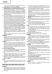
... 75 mm height in the left or right side of the blade, the short cut -off portion will be performed by sliding the round portion of the saw backwards with the hand that the clamp lever is secured and the motor head is still rotating, the cut -off piece ... lower limit position (refer to "2. Starting from the workpiece. Installing the holders ... (Optional accessory) The holders help keep longer workpieces stable and in place during compound cutting because the saw blade may become jammed against the saw blade is clamped. Always turn the power off is more than 25 mm long. Turning...
... 75 mm height in the left or right side of the blade, the short cut -off portion will be performed by sliding the round portion of the saw backwards with the hand that the clamp lever is secured and the motor head is still rotating, the cut -off piece ... lower limit position (refer to "2. Starting from the workpiece. Installing the holders ... (Optional accessory) The holders help keep longer workpieces stable and in place during compound cutting because the saw blade may become jammed against the saw blade is clamped. Always turn the power off is more than 25 mm long. Turning...
User Guide
Page 62
... may break or chip saw blade. 25. Dismounting the saw blade Dismount the saw blade and the surface of the workpiece, remove the unneeded portion with the 6 mm knob bolt as shown in spindle lock and loosen 10 mm bolt with 17 mm box wrench (standard accessory) while applying pressure on either.... ⅜ Tighten the 10 mm bolt so it to securely attach the the crown molding in paragraph 1 above. The saw blade can be cut by standard accessories (17 mm box wrench) as shown in the workpiece can easily be shown in diameter. NOTE When cutting a single groove at either the ...
... may break or chip saw blade. 25. Dismounting the saw blade Dismount the saw blade and the surface of the workpiece, remove the unneeded portion with the 6 mm knob bolt as shown in spindle lock and loosen 10 mm bolt with 17 mm box wrench (standard accessory) while applying pressure on either.... ⅜ Tighten the 10 mm bolt so it to securely attach the the crown molding in paragraph 1 above. The saw blade can be cut by standard accessories (17 mm box wrench) as shown in the workpiece can easily be shown in diameter. NOTE When cutting a single groove at either the ...
Parts List
Page 9
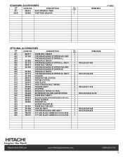
USED 501 985051 BOX WRENCH 17MM 1 502A 322955 DUST BAG (BLACK) 1 REMARKS C12RSH OPTIONAL ACCESSORIES ITEM NO. USED REMARKS 1 1 1 1 1 INCLUD.601-604 2 1 1 1 1 INCLUD.606-609 2 2 2 2 2 2 INCLUD.611-615 1 1 1 INCLUD.606.616-618 1 1 1 1 1 1 1 INCLUD.620-625 1 INCLUD.605.626 ... SCREW HOLDER (B) 625 321551 KNOB BOLT M10X54 626 321388 VISE (B) ASS'Y 627 321434 CROWN MOLDING VISE ASS'Y 628 726100 TCT SAW BLADE 305MM-D25.4 HOLE-NT60 629 725101 TCT SAW BLADE 305MM-D25.4 HOLE-NT90 NO. DESCRIPTION NO. CODE NO. STANDARD ACCESSORIES ITEM NO.
USED 501 985051 BOX WRENCH 17MM 1 502A 322955 DUST BAG (BLACK) 1 REMARKS C12RSH OPTIONAL ACCESSORIES ITEM NO. USED REMARKS 1 1 1 1 1 INCLUD.601-604 2 1 1 1 1 INCLUD.606-609 2 2 2 2 2 2 INCLUD.611-615 1 1 1 INCLUD.606.616-618 1 1 1 1 1 1 1 INCLUD.620-625 1 INCLUD.605.626 ... SCREW HOLDER (B) 625 321551 KNOB BOLT M10X54 626 321388 VISE (B) ASS'Y 627 321434 CROWN MOLDING VISE ASS'Y 628 726100 TCT SAW BLADE 305MM-D25.4 HOLE-NT60 629 725101 TCT SAW BLADE 305MM-D25.4 HOLE-NT90 NO. DESCRIPTION NO. CODE NO. STANDARD ACCESSORIES ITEM NO.