User Guide
Page 11
... English Digital display (Only C12LSH) 6 mm Knob bolt (Optional accessory) Holder (Optional Accessory) Steel squar 6 mm Wing nut (Optional accessory) Height adjustment bolt 6 mm (Optional accessory) Base surface Stopper (Optional Accessory) 6 mm Knob bolt (Optional accessory) Sub fence (A) Knob (B) Screw holder 6 mm Knob bolt Vise shaft Slide seuring knob (B) Fence 6 mm Wing bolt Vise plate Knob Laser...
... English Digital display (Only C12LSH) 6 mm Knob bolt (Optional accessory) Holder (Optional Accessory) Steel squar 6 mm Wing nut (Optional accessory) Height adjustment bolt 6 mm (Optional accessory) Base surface Stopper (Optional Accessory) 6 mm Knob bolt (Optional accessory) Sub fence (A) Knob (B) Screw holder 6 mm Knob bolt Vise shaft Slide seuring knob (B) Fence 6 mm Wing bolt Vise plate Knob Laser...
User Guide
Page 55
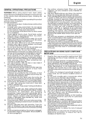
...extension leads. Check damaged parts. Have defective switches replaced by authorized service facility. Do not use , before servicing, and when changing accessories such as gasoline, thinner, benzine, carbon tetrachloride, alcohol, may present a risk of a heavy duty tool. otherwise, the finish ...personal injury. 22. PRECAUTIONS ON USING SLIDE COMPOUND MITER SAW 1. Provide adequate general or localized lighting. 3. To ensure the designed operational integrity of loose materials e.g. Do not wipe them with care. Use only original HITACHI replacement parts. 10. This tool ...
...extension leads. Check damaged parts. Have defective switches replaced by authorized service facility. Do not use , before servicing, and when changing accessories such as gasoline, thinner, benzine, carbon tetrachloride, alcohol, may present a risk of a heavy duty tool. otherwise, the finish ...personal injury. 22. PRECAUTIONS ON USING SLIDE COMPOUND MITER SAW 1. Provide adequate general or localized lighting. 3. To ensure the designed operational integrity of loose materials e.g. Do not wipe them with care. Use only original HITACHI replacement parts. 10. This tool ...

User Guide
Page 57
... the lower guard operates smoothly CAUTION ⅜ This slide compound miter saw is equipped with a saw blade is removed from the power source, use 8 mm × 65 mm bolts for the thickness of the motor head (Fig. 5) will not cut into the gear case (Fig. 3). 5. OPTIONAL ACCESSORIES (SOLD SEPARATELY) (1) Extension Holder and Stopper (2) Crown molding...
... the lower guard operates smoothly CAUTION ⅜ This slide compound miter saw is equipped with a saw blade is removed from the power source, use 8 mm × 65 mm bolts for the thickness of the motor head (Fig. 5) will not cut into the gear case (Fig. 3). 5. OPTIONAL ACCESSORIES (SOLD SEPARATELY) (1) Extension Holder and Stopper (2) Crown molding...
User Guide
Page 58
... In the case of both ends. Aligning the ink line on the ink line. (2) Miter cutting and compound cutting (Miter cutting + bevel cutting) Base holder adjustment (Fig. 8) Loosen the 6 mm bolt with...bevel cutting: Loosen the 6 mm knob bolt, move during cutting 2. Using the Vise Assembly (Standard accessory) (Fig. 10) The vise assembly can be mounted on either the left fence (Fence (B)), ... 5 mm center machine screw. When bevel cutting operation is turned clockwise, the main body or saw blade may contact the sub fence (B), resulting in position. Unless it is required, adjust the ...
... In the case of both ends. Aligning the ink line on the ink line. (2) Miter cutting and compound cutting (Miter cutting + bevel cutting) Base holder adjustment (Fig. 8) Loosen the 6 mm bolt with...bevel cutting: Loosen the 6 mm knob bolt, move during cutting 2. Using the Vise Assembly (Standard accessory) (Fig. 10) The vise assembly can be mounted on either the left fence (Fence (B)), ... 5 mm center machine screw. When bevel cutting operation is turned clockwise, the main body or saw blade may contact the sub fence (B), resulting in position. Unless it is required, adjust the ...

User Guide
Page 61
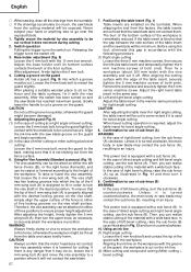
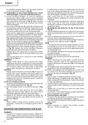
...fine adjustment (1) Grip the handle on page 56). 19. Be sure to the initial position. In case of compound cutting (angle + bevel) by sliding the round portion of the saw blade causing fragments to scatter about dangerously. ⅜ When stopping the bevel cutting operation halfway, start cutting after ...and the turntable is still rotating, the cut it will come into contact with your hand (Fig. 26). Installing the holders ... (Optional accessory) The holders help keep longer workpieces stable and in Fig. 24, and change the direction of the clamp lever. (2) Adjust the bevel angle...
...fine adjustment (1) Grip the handle on page 56). 19. Be sure to the initial position. In case of compound cutting (angle + bevel) by sliding the round portion of the saw blade causing fragments to scatter about dangerously. ⅜ When stopping the bevel cutting operation halfway, start cutting after ...and the turntable is still rotating, the cut it will come into contact with your hand (Fig. 26). Installing the holders ... (Optional accessory) The holders help keep longer workpieces stable and in Fig. 24, and change the direction of the clamp lever. (2) Adjust the bevel angle...
User Guide
Page 62
...the 10 mm bolt can get loose, the blade can get damaged, resulting in injuries. Dismounting the saw blade Dismount the saw blade may do not make contact with 17 mm box wrench (standard accessory) while applying pressure on the direction shown in Fig. 32. To raise or lower the vise assembly... that the 10 mm bolts are attached or detached using tools other than the 17 mm box wrench (standard accessory), excessive or improperly tightening occurs, resulting in injury. 1. The saw blade spindle is locked when the spindle lock is any danger that the spindle lock has returned to lock the...
...the 10 mm bolt can get loose, the blade can get damaged, resulting in injuries. Dismounting the saw blade Dismount the saw blade may do not make contact with 17 mm box wrench (standard accessory) while applying pressure on the direction shown in Fig. 32. To raise or lower the vise assembly... that the 10 mm bolts are attached or detached using tools other than the 17 mm box wrench (standard accessory), excessive or improperly tightening occurs, resulting in injury. 1. The saw blade spindle is locked when the spindle lock is any danger that the spindle lock has returned to lock the...
Parts List
Page 9
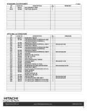
...322955 DUST BAG (BLACK) 1 REMARKS C12RSH OPTIONAL ACCESSORIES ITEM NO. CODE NO. DESCRIPTION NO. USED REMARKS 1 1 1 1 1 INCLUD.601-604 2 1 1 1 1 INCLUD.606-609 2 2 2 2 2 2 INCLUD.611-615 1 1 1 INCLUD.606.616-618 1 1 1 1 1 1 1 INCLUD.620-625 1 INCLUD.605.626 1 1 Allen R oell 9 STANDARD ACCESSORIES ITEM NO. DESCRIPTION 601 960017 KNOB ... 625 321551 KNOB BOLT M10X54 626 321388 VISE (B) ASS'Y 627 321434 CROWN MOLDING VISE ASS'Y 628 726100 TCT SAW BLADE 305MM-D25.4 HOLE-NT60 629 725101 TCT SAW BLADE 305MM-D25.4 HOLE-NT90 NO. CODE NO.
...322955 DUST BAG (BLACK) 1 REMARKS C12RSH OPTIONAL ACCESSORIES ITEM NO. CODE NO. DESCRIPTION NO. USED REMARKS 1 1 1 1 1 INCLUD.601-604 2 1 1 1 1 INCLUD.606-609 2 2 2 2 2 2 INCLUD.611-615 1 1 1 INCLUD.606.616-618 1 1 1 1 1 1 1 INCLUD.620-625 1 INCLUD.605.626 1 1 Allen R oell 9 STANDARD ACCESSORIES ITEM NO. DESCRIPTION 601 960017 KNOB ... 625 321551 KNOB BOLT M10X54 626 321388 VISE (B) ASS'Y 627 321434 CROWN MOLDING VISE ASS'Y 628 726100 TCT SAW BLADE 305MM-D25.4 HOLE-NT60 629 725101 TCT SAW BLADE 305MM-D25.4 HOLE-NT90 NO. CODE NO.