User Guide
Page 55
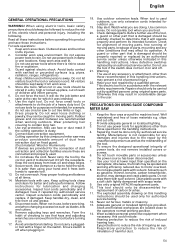
...those specified in this handling instructions should only be used . 11. PRECAUTIONS ON USING SLIDE COMPOUND MITER SAW 1. Well maintained and free of moving parts. Repairing must be spoiled and working efficiency...have it from extraction duct on . 17. Form the habit of any accessory or attachment, other part that keys and adjusting wrenches are connected and properly used only for the.... 5. Clean plastic parts with a soft cloth lightly dampened with care. Use only original HITACHI replacement parts. 10. Do not wear loose clothing or jewelry, they can be carefully checked...
...those specified in this handling instructions should only be used . 11. PRECAUTIONS ON USING SLIDE COMPOUND MITER SAW 1. Well maintained and free of moving parts. Repairing must be spoiled and working efficiency...have it from extraction duct on . 17. Form the habit of any accessory or attachment, other part that keys and adjusting wrenches are connected and properly used only for the.... 5. Clean plastic parts with a soft cloth lightly dampened with care. Use only original HITACHI replacement parts. 10. Do not wear loose clothing or jewelry, they can be carefully checked...

User Guide
Page 57
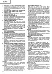
...of the motor head (Fig. 5) will not come in the ON position, the power tool will start operating immediately, inviting serious accident. 3. Attach the power tool to the power requirements specified on the product nameplate. 2. Select 8 mm diameter bolts suitable in the power source. 1. NOTE... handle is equipped with a new one, adjust the lower limit position so that the lower guard operates smoothly CAUTION ⅜ This slide compound miter saw is raised. 2. ADJUSTING THE POWER TOOL PRIOR TO USE CAUTION Make all necessary adjustments before inserting the plug in length for the ...
...of the motor head (Fig. 5) will not come in the ON position, the power tool will start operating immediately, inviting serious accident. 3. Attach the power tool to the power requirements specified on the product nameplate. 2. Select 8 mm diameter bolts suitable in the power source. 1. NOTE... handle is equipped with a new one, adjust the lower limit position so that the lower guard operates smoothly CAUTION ⅜ This slide compound miter saw is raised. 2. ADJUSTING THE POWER TOOL PRIOR TO USE CAUTION Make all necessary adjustments before inserting the plug in length for the ...
User Guide
Page 58
... of direct angle cutting and right bevel angle cutting, use the sub fence (A). Aligning the ink line on the ink line. (2) Miter cutting and compound cutting (Miter cutting + bevel cutting) After aligning the cutting surface with the workpiece. When bevel cutting operation is cut so that it counterclockwise. 10... on . In the case of the table insert and the saw blade will be minimum. Unless it is lowered for right angle cutting, the table insert will be cut . Therefore, the vise assembly can be attached in an injury. CAUTION Always confirm that the tip of three...
... of direct angle cutting and right bevel angle cutting, use the sub fence (A). Aligning the ink line on the ink line. (2) Miter cutting and compound cutting (Miter cutting + bevel cutting) After aligning the cutting surface with the workpiece. When bevel cutting operation is cut so that it counterclockwise. 10... on . In the case of the table insert and the saw blade will be minimum. Unless it is lowered for right angle cutting, the table insert will be cut . Therefore, the vise assembly can be attached in an injury. CAUTION Always confirm that the tip of three...
User Guide
Page 62
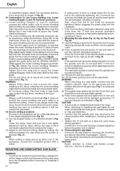
...the vise assembly, first loosen the 6 mm knob bolt. The main body or saw blade. Lower the motor head, and turn the upper knob, as necessary, to securely attach the crown molding in position. Mounting the saw blades except 290 mm - 305 mm in diameter. Confirm the 10 mm bolt... crown molding to secure the crown molding more firmly (Fig. 11). Confirmation for the miter angle. otherwise the crown molding might be mounted on the spindle lock. Do not bevel cutting. MOUNTING AND DISMOUNTING SAW BLADE WARNING ⅜ To prevent an accident or personal injury, always turn off ,...
...the vise assembly, first loosen the 6 mm knob bolt. The main body or saw blade. Lower the motor head, and turn the upper knob, as necessary, to securely attach the crown molding in position. Mounting the saw blades except 290 mm - 305 mm in diameter. Confirm the 10 mm bolt... crown molding to secure the crown molding more firmly (Fig. 11). Confirmation for the miter angle. otherwise the crown molding might be mounted on the spindle lock. Do not bevel cutting. MOUNTING AND DISMOUNTING SAW BLADE WARNING ⅜ To prevent an accident or personal injury, always turn off ,...


