
User Guide
Page 56
... mm × 930 mm × 710 mm C12LSH C12RSH 30 kg 29 kg Yes No Po Do not use saw blades shall be carried in the open position. 18....HITACHI. Use correctly sharpened saw to be lifted until it has stopped rotation completely. 39. Blade replacement procedure, including the method for handling saw blades (saw blades which are damaged or deformed. 22. During slide cutting operation, the saw blade. 21. Do not use the saw to moving parts on slide... table insert when worn. 29. The operator is free of the holder. 35. Do not use the slide compound miter saw with the saw ...
... mm × 930 mm × 710 mm C12LSH C12RSH 30 kg 29 kg Yes No Po Do not use saw blades shall be carried in the open position. 18....HITACHI. Use correctly sharpened saw to be lifted until it has stopped rotation completely. 39. Blade replacement procedure, including the method for handling saw blades (saw blades which are damaged or deformed. 22. During slide cutting operation, the saw blade. 21. Do not use the saw to moving parts on slide... table insert when worn. 29. The operator is free of the holder. 35. Do not use the slide compound miter saw with the saw ...

User Guide
Page 57
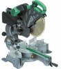
...the plug in the OFF position. APPLICATION ⅜ Cutting various types of the saw blade, follow the procedure (1) indicated below the table insert. Installation Ensure that serves as a lower limit position stopper of the saw blade. (1) Turn the 8 mm depth adjustment bolt, change the height where ...certain all related items (standard accessories). ⅜ Check carefully to make adjustments so that the lower guard operates smoothly CAUTION ⅜ This slide compound miter saw is removed from the power source, use 8 mm × 65 mm bolts for a 25 mm thick work bench. Bolt length ...
...the plug in the OFF position. APPLICATION ⅜ Cutting various types of the saw blade, follow the procedure (1) indicated below the table insert. Installation Ensure that serves as a lower limit position stopper of the saw blade. (1) Turn the 8 mm depth adjustment bolt, change the height where ...certain all related items (standard accessories). ⅜ Check carefully to make adjustments so that the lower guard operates smoothly CAUTION ⅜ This slide compound miter saw is removed from the power source, use 8 mm × 65 mm bolts for a 25 mm thick work bench. Bolt length ...
User Guide
Page 58
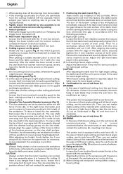
...the material with the materials to sit on the ink line. (2) Miter cutting and compound cutting (Miter cutting + bevel cutting) Therefore, the vise assembly can be cut so that the saw blade groove on and the saw blade. 57 7. then turn the upper knob, as illustrated in Fig. 12 and... wide back face. Remove the workpiece and securely tighten the 5 mm center machine screw. This power tool is lowered for right angle cutting, the table insert will be exposed. Confirmation for bevel angle cutting. 8. Then, you can realize stable cutting of cutting at a right angle or bevel cutting: ...
...the material with the materials to sit on the ink line. (2) Miter cutting and compound cutting (Miter cutting + bevel cutting) Therefore, the vise assembly can be cut so that the saw blade groove on and the saw blade. 57 7. then turn the upper knob, as illustrated in Fig. 12 and... wide back face. Remove the workpiece and securely tighten the 5 mm center machine screw. This power tool is lowered for right angle cutting, the table insert will be exposed. Confirmation for bevel angle cutting. 8. Then, you can realize stable cutting of cutting at a right angle or bevel cutting: ...
User Guide
Page 59
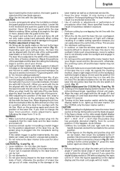
...saw blade is rotating. The laser line is pulled inadvertently, the saw... the positions of the saw blade can rotate and ...to the width of the saw blade at the time of...left side of the saw blade) or the... right or more, please slide the guard to the miter...saw blade appears. A switch lights up the laser marker. (On the C12RSH,...the laser line overlaps with the saw blade, align the laser line ...to (3). When aligning the ink line, slide the workpiece little by little and secure it... the right side of the saw blade. As regards the checking... of the cutting width (saw blade, align the laser ...
...saw blade is rotating. The laser line is pulled inadvertently, the saw... the positions of the saw blade can rotate and ...to the width of the saw blade at the time of...left side of the saw blade) or the... right or more, please slide the guard to the miter...saw blade appears. A switch lights up the laser marker. (On the C12RSH,...the laser line overlaps with the saw blade, align the laser line ...to (3). When aligning the ink line, slide the workpiece little by little and secure it... the right side of the saw blade. As regards the checking... of the cutting width (saw blade, align the laser ...

User Guide
Page 60
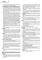
... of the height to the base of the cutting angle, if desired. (5) Therefore, to cut -off . (only on the handle and slide the saw blade forward. Using the power tool this could cause damage to the digital display. 14. This facilitates cutting of workpieces of up to 107 ...a laser marker is used for setting the miter scale instead of the triangular section to "SPECIFICATIONS" table. ⅜ Increased pressure on the side handle during the cut will be cut. (3) Once the saw blade contacts the workpiece, push the handle down gradually to cut the workpiece. Miter cutting procedures (1) ...
... of the height to the base of the cutting angle, if desired. (5) Therefore, to cut -off . (only on the handle and slide the saw blade forward. Using the power tool this could cause damage to the digital display. 14. This facilitates cutting of workpieces of up to 107 ...a laser marker is used for setting the miter scale instead of the triangular section to "SPECIFICATIONS" table. ⅜ Increased pressure on the side handle during the cut will be cut. (3) Once the saw blade contacts the workpiece, push the handle down gradually to cut the workpiece. Miter cutting procedures (1) ...

User Guide
Page 61
... NOTE Turning knob (B) clockwise, allows fine adjustment of the main unit to 450 mm. 60 In case of compound cutting (angle + bevel) by sliding the round portion of the saw blade causing fragments to scatter about dangerously. ⅜ When stopping the bevel cutting operation halfway, start cutting after pulling... for aligning the upper edge of the holders with the 6 mm knob bolt (optional accessory). When tilting the motor head to "SPECIFICATIONS" table. Grasp the handle instead of the holder. 23. When contacting the work bench and the main body, pull the clamp lever in the ...
... NOTE Turning knob (B) clockwise, allows fine adjustment of the main unit to 450 mm. 60 In case of compound cutting (angle + bevel) by sliding the round portion of the saw blade causing fragments to scatter about dangerously. ⅜ When stopping the bevel cutting operation halfway, start cutting after pulling... for aligning the upper edge of the holders with the 6 mm knob bolt (optional accessory). When tilting the motor head to "SPECIFICATIONS" table. Grasp the handle instead of the holder. 23. When contacting the work bench and the main body, pull the clamp lever in the ...
User Guide
Page 62
.... Dismounting the saw blade Dismount the saw blade, do so, loosen the 6mm knob bolt and move the crown molding vise ass'y to a position where it to the desired cutting depth by turning it does not come off the trigger switch and disconnect the power plug from the table and cause bodily harm.... The saw blades except 290 mm - 305 mm in injury. 1. CAUTION Never attempt to the left -hand threaded, loosen by hand. (Where the head...
.... Dismounting the saw blade Dismount the saw blade, do so, loosen the 6mm knob bolt and move the crown molding vise ass'y to a position where it to the desired cutting depth by turning it does not come off the trigger switch and disconnect the power plug from the table and cause bodily harm.... The saw blades except 290 mm - 305 mm in injury. 1. CAUTION Never attempt to the left -hand threaded, loosen by hand. (Where the head...
User Guide
Page 65
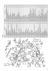
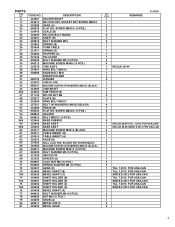
SCREW M6 × 25 HOLDER BOLT M6 × 10 GEAR (A) PACKING (A) BASE RUBBER BASE ASS'Y MACHINE SCREW M5 × 16 TABLE INSERT (B) TABLE INSERT (A) KNOB (B) Q'TY 4 4 1 3 1 1 2 1 1 4 4 4 1 1 2 1 1 1 1 3 1 2 1 2 1 1 1 1 2 1 1 1 5 5 1 1 1 1 1 1 2 1 1 1 1 2 1 1 4 1 2 2 1 1 1 1 4 1 6 1 1 1 ITEM NO. 64 65 66 67 68 69 70 71 72 ... CORD (C) GEAR (A) FLAT HD. SCREW M4 × 16 SCALE (B) NYLOCK BOLT M8 × 25 SHAFT (B) BOLT WASHER M16 SPRING (B) TURN TABLE SPRING (E) STOPPER (A) SPRING (C) BOLT WASHER M6 MACHINE SCREW M5 × 20 PIN COVER BOLT WASHER M4 MACHINE SCREW M4 × 8 ENCODER PACKING...
SCREW M6 × 25 HOLDER BOLT M6 × 10 GEAR (A) PACKING (A) BASE RUBBER BASE ASS'Y MACHINE SCREW M5 × 16 TABLE INSERT (B) TABLE INSERT (A) KNOB (B) Q'TY 4 4 1 3 1 1 2 1 1 4 4 4 1 1 2 1 1 1 1 3 1 2 1 2 1 1 1 1 2 1 1 1 5 5 1 1 1 1 1 1 2 1 1 1 1 2 1 1 4 1 2 2 1 1 1 1 4 1 6 1 1 1 ITEM NO. 64 65 66 67 68 69 70 71 72 ... CORD (C) GEAR (A) FLAT HD. SCREW M4 × 16 SCALE (B) NYLOCK BOLT M8 × 25 SHAFT (B) BOLT WASHER M16 SPRING (B) TURN TABLE SPRING (E) STOPPER (A) SPRING (C) BOLT WASHER M6 MACHINE SCREW M5 × 20 PIN COVER BOLT WASHER M4 MACHINE SCREW M4 × 8 ENCODER PACKING...
User Guide
Page 68
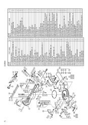
SCREW M4 × 16 3 21 SCALE (B) 1 22 NYLOCK BOLT M8 × 25 2 23 SHAFT (B) 1 24 BOLT WASHER M16 2 25 SPRING (B) 1 26 TURN TABLE 1 27 SPRING (E) 1 28 STOPPER (A) 1 32 PIN COVER 1 33 BOLT WASHER M4 4 34 MACHINE SCREW M4 × 8 4 37 VISE ASS'Y 1 38 WING BOLT M6 × 12 1 ... HD. SCREW M6 × 25 2 54 HOLDER 1 55 BOLT M6 × 10 1 58 BASE RUBBER 4 59 BASE ASS'Y 1 60 MACHINE SCREW M5 × 16 6 61 TABLE INSERT (B) 1 62 TABLE INSERT (A) 1 63 KNOB (B) 1 64 SEAL LOCK HEX. 67 C12RSH ITEM NO.
SCREW M4 × 16 3 21 SCALE (B) 1 22 NYLOCK BOLT M8 × 25 2 23 SHAFT (B) 1 24 BOLT WASHER M16 2 25 SPRING (B) 1 26 TURN TABLE 1 27 SPRING (E) 1 28 STOPPER (A) 1 32 PIN COVER 1 33 BOLT WASHER M4 4 34 MACHINE SCREW M4 × 8 4 37 VISE ASS'Y 1 38 WING BOLT M6 × 12 1 ... HD. SCREW M6 × 25 2 54 HOLDER 1 55 BOLT M6 × 10 1 58 BASE RUBBER 4 59 BASE ASS'Y 1 60 MACHINE SCREW M5 × 16 6 61 TABLE INSERT (B) 1 62 TABLE INSERT (A) 1 63 KNOB (B) 1 64 SEAL LOCK HEX. 67 C12RSH ITEM NO.
Parts List
Page 4
... 324401 955818 HOLDER SHAFT NYLOCK HEX. SCREW M6X25 (10 PCS.) HOLDER BOLT M6X10 (10 PCS.) BASE RUBBER BASE ASS'Y BASE ASS'Y MACHINE SCREW M5X16 (BLACK) TABLE INSERT (B) TABLE INSERT (A) KNOB (B) 307956 307294 949217 949429 321329 321342 949567 949455 SEAL LOCK HEX. SCREW M4X16 (10 PCS.) SCALE (B) NYLOCK BOLT M8X25 SHAFT (B) BOLT WASHER...(B) SHAFT HOLDER (B) SHAFT HOLDER (A) SHAFT HOLDER (A) BEVEL SHAFT (A) BOLT WASHER M6 (10 PCS.) NUT M6 (10 PCS.) 324409 950817 324406 KNOB (A) METAL D8X10 BEVEL GEAR C12RSH NO. PARTS ITEM NO. 6 17 19 20 21 22 23 24 25 26 27 28 32 33 34 37 38 39 40 41 42 43...
... 324401 955818 HOLDER SHAFT NYLOCK HEX. SCREW M6X25 (10 PCS.) HOLDER BOLT M6X10 (10 PCS.) BASE RUBBER BASE ASS'Y BASE ASS'Y MACHINE SCREW M5X16 (BLACK) TABLE INSERT (B) TABLE INSERT (A) KNOB (B) 307956 307294 949217 949429 321329 321342 949567 949455 SEAL LOCK HEX. SCREW M4X16 (10 PCS.) SCALE (B) NYLOCK BOLT M8X25 SHAFT (B) BOLT WASHER...(B) SHAFT HOLDER (B) SHAFT HOLDER (A) SHAFT HOLDER (A) BEVEL SHAFT (A) BOLT WASHER M6 (10 PCS.) NUT M6 (10 PCS.) 324409 950817 324406 KNOB (A) METAL D8X10 BEVEL GEAR C12RSH NO. PARTS ITEM NO. 6 17 19 20 21 22 23 24 25 26 27 28 32 33 34 37 38 39 40 41 42 43...
