Service Manual
Page 10
...Calibrate a replacement ADF assembly 214 ADF roller assembly and separation pad 215 Reinstall the ADF roller assembly 217 Control-panel overlay ...218 Control-panel assembly 219 Remove the control-panel assembly 219 Right door (optional paper feeder 221 External panels, covers, doors, and scanner assembly 223 Identification and location ... rear cover 238 Right-front cover ...239 Remove the right-front cover 239 Reinstall the power button 241 Scanner assembly ...242 Remove the scanner assembly 242 Delivery cover ...245 Remove the delivery cover 245 Left-upper cover ...247 viii ENWW
...Calibrate a replacement ADF assembly 214 ADF roller assembly and separation pad 215 Reinstall the ADF roller assembly 217 Control-panel overlay ...218 Control-panel assembly 219 Remove the control-panel assembly 219 Right door (optional paper feeder 221 External panels, covers, doors, and scanner assembly 223 Identification and location ... rear cover 238 Right-front cover ...239 Remove the right-front cover 239 Reinstall the power button 241 Scanner assembly ...242 Remove the scanner assembly 242 Delivery cover ...245 Remove the delivery cover 245 Left-upper cover ...247 viii ENWW
Service Manual
Page 12
... the pickup motor 313 Lifter-drive assembly ...314 Remove the lifter-drive assembly 314 Cassette-pickup drive assembly 316 Remove the cassette-pickup drive assembly 316 Reinstall the cassette-pickup drive assembly 321 Cassette-pickup assembly 323 Remove the cassette-pickup assembly 323 Laser/scanner assembly (Y/M 325 Remove the laser/scanner assembly (Y/M 325 Laser/scanner assembly (C/Bk 332 Remove the laser/scanner assembly (C/Bk 332 Reinstall the protective glass...
... the pickup motor 313 Lifter-drive assembly ...314 Remove the lifter-drive assembly 314 Cassette-pickup drive assembly 316 Remove the cassette-pickup drive assembly 316 Reinstall the cassette-pickup drive assembly 321 Cassette-pickup assembly 323 Remove the cassette-pickup assembly 323 Laser/scanner assembly (Y/M 325 Remove the laser/scanner assembly (Y/M 325 Laser/scanner assembly (C/Bk 332 Remove the laser/scanner assembly (C/Bk 332 Reinstall the protective glass...
Service Manual
Page 15
... kits ...515 Service manuals and user documentation 518 Screws ...519 How to use the parts lists and diagrams 519 ADF and scanner assemblies ...520 External covers, panels, and doors 522 Right door assembly ...524 Internal components ...526 Internal components (1 of 5 526 Internal components (2 of 5 528 Internal components (3 of 5 530 Internal components (4 of 5 532...
... kits ...515 Service manuals and user documentation 518 Screws ...519 How to use the parts lists and diagrams 519 ADF and scanner assemblies ...520 External covers, panels, and doors 522 Right door assembly ...524 Internal components ...526 Internal components (1 of 5 526 Internal components (2 of 5 528 Internal components (3 of 5 530 Internal components (4 of 5 532...
Service Manual
Page 18
... ...514 Table 8-6 Service kit contents ...515 Table 8-7 Service manuals and user documentation 518 Table 8-8 Common fasteners ...519 Table 8-9 ADF/scanner assembly ...521 Table 8-10 External covers, panels, and doors 523 Table 8-11 Right door assembly ...525 Table 8-12 Internal components (1 of 5) ...527 Table 8-13 Internal components (2 of 5) ...529 Table 8-14 Internal components (3 of... that the product detects ...164 Table 5-15 Electrical components for the paper feeder 167 Table 6-1 DC controller connectors ...183 Table 6-2 External panels, covers, doors, and scanner assembly;
... ...514 Table 8-6 Service kit contents ...515 Table 8-7 Service manuals and user documentation 518 Table 8-8 Common fasteners ...519 Table 8-9 ADF/scanner assembly ...521 Table 8-10 External covers, panels, and doors 523 Table 8-11 Right door assembly ...525 Table 8-12 Internal components (1 of 5) ...527 Table 8-13 Internal components (2 of 5) ...529 Table 8-14 Internal components (3 of... that the product detects ...164 Table 5-15 Electrical components for the paper feeder 167 Table 6-1 DC controller connectors ...183 Table 6-2 External panels, covers, doors, and scanner assembly;
Service Manual
Page 23
... roller ...206 Remove the transfer roller (2 of 3 207 Remove the secondary transfer assembly (1 of 2 207 Remove the secondary transfer assembly (2 of 2 208 Reinstall the secondary transfer assembly 208 Remove the intermediate transfer belt (1 of 3 209 Remove the intermediate transfer belt...assembly 217 Remove the control-panel overlay (1 of 2 218 Remove the control-panel overlay (2 of 2 218 Remove the control-panel assembly (1 of 3 219 Remove the control-panel assembly (2 of 3 219 Remove the control-panel assembly (3 of 3 222 External panels, covers, doors, and scanner assembly;...
... roller ...206 Remove the transfer roller (2 of 3 207 Remove the secondary transfer assembly (1 of 2 207 Remove the secondary transfer assembly (2 of 2 208 Reinstall the secondary transfer assembly 208 Remove the intermediate transfer belt (1 of 3 209 Remove the intermediate transfer belt...assembly 217 Remove the control-panel overlay (1 of 2 218 Remove the control-panel overlay (2 of 2 218 Remove the control-panel assembly (1 of 3 219 Remove the control-panel assembly (2 of 3 219 Remove the control-panel assembly (3 of 3 222 External panels, covers, doors, and scanner assembly;...

Service Manual
Page 24
... 6-96 Reinstall the power button ...241 Figure 6-97 Remove the scanner assembly (1 of 6 242 Figure 6-98 Remove the scanner assembly (2 of 6 242 Figure 6-99 Remove the scanner assembly (3 of 6 243 Figure 6-100 Remove the scanner assembly (4 of 6 243 Figure 6-101 Remove the scanner assembly (5 of 6 244 Figure 6-102 Remove the scanner assembly (6 of 6 244 Figure 6-103 Remove the delivery cover (1 of 3 245...
... 6-96 Reinstall the power button ...241 Figure 6-97 Remove the scanner assembly (1 of 6 242 Figure 6-98 Remove the scanner assembly (2 of 6 242 Figure 6-99 Remove the scanner assembly (3 of 6 243 Figure 6-100 Remove the scanner assembly (4 of 6 243 Figure 6-101 Remove the scanner assembly (5 of 6 244 Figure 6-102 Remove the scanner assembly (6 of 6 244 Figure 6-103 Remove the delivery cover (1 of 3 245...

Service Manual
Page 27
... 3 324 Remove the laser/scanner assembly (Y/M) (1 of 12 325 Remove the laser/scanner assembly (Y/M) (2 of 12 326 Remove the laser/scanner assembly (Y/M) (3 of 12 326 Remove the laser/scanner assembly (Y/M) (4 of 12 327 Remove the laser/scanner assembly (Y/M) (5 of 12 327 Remove the laser/scanner assembly (Y/M) (6 of 12 328 Remove the laser/scanner assembly (Y/M) (7 of 12 328 Remove the laser/scanner assembly (Y/M) (8 of 12 329 Remove the laser/scanner assembly (Y/M) (9 of 12 329 Remove the laser/scanner assembly (Y/M) (10 of...
... 3 324 Remove the laser/scanner assembly (Y/M) (1 of 12 325 Remove the laser/scanner assembly (Y/M) (2 of 12 326 Remove the laser/scanner assembly (Y/M) (3 of 12 326 Remove the laser/scanner assembly (Y/M) (4 of 12 327 Remove the laser/scanner assembly (Y/M) (5 of 12 327 Remove the laser/scanner assembly (Y/M) (6 of 12 328 Remove the laser/scanner assembly (Y/M) (7 of 12 328 Remove the laser/scanner assembly (Y/M) (8 of 12 329 Remove the laser/scanner assembly (Y/M) (9 of 12 329 Remove the laser/scanner assembly (Y/M) (10 of...
Service Manual
Page 28
... 6-282 Figure 6-283 Figure 6-284 Figure 6-285 Figure 6-286 Figure 6-287 Figure 6-288 Remove the laser/scanner assembly (C/Bk) (3 of 7 333 Remove the laser/scanner assembly (C/Bk) (4 of 7 334 Remove the laser/scanner assembly (C/Bk) (5 of 7 334 Remove the laser/scanner assembly (C/Bk) (6 of 7 335 Remove the laser/scanner assembly (C/Bk) (7 of 7 335 Reinstall the PGC actuators (1 of 5 336 Reinstall the PGC actuators (2 of 5 336...
... 6-282 Figure 6-283 Figure 6-284 Figure 6-285 Figure 6-286 Figure 6-287 Figure 6-288 Remove the laser/scanner assembly (C/Bk) (3 of 7 333 Remove the laser/scanner assembly (C/Bk) (4 of 7 334 Remove the laser/scanner assembly (C/Bk) (5 of 7 334 Remove the laser/scanner assembly (C/Bk) (6 of 7 335 Remove the laser/scanner assembly (C/Bk) (7 of 7 335 Reinstall the PGC actuators (1 of 5 336 Reinstall the PGC actuators (2 of 5 336...

Service Manual
Page 30
...7-47 Configuration page ...436 Figure 7-48 HP embedded Jetdirect page ...438 Figure 7-49 Embedded protocol page ...439 Figure 7-50 Jam locations ...473 Figure 8-1 ADF/scanner assembly ...520 Figure 8-2 External covers, panels, and doors 522 Figure 8-3 Right door assembly ...524 Figure 8-4 Internal components (1 of... Fuser ...536 Figure 8-10 250-sheet cassette ...538 Figure 8-11 250-sheet cassette paper pickup assembly 540 Figure 8-12 Registration assembly ...542 Figure 8-13 Paper-delivery assembly ...544 Figure 8-14 PCAs ...546 Figure 8-15 Formatter components ...548 Figure 8-16 500-sheet ...
...7-47 Configuration page ...436 Figure 7-48 HP embedded Jetdirect page ...438 Figure 7-49 Embedded protocol page ...439 Figure 7-50 Jam locations ...473 Figure 8-1 ADF/scanner assembly ...520 Figure 8-2 External covers, panels, and doors 522 Figure 8-3 Right door assembly ...524 Figure 8-4 Internal components (1 of... Fuser ...536 Figure 8-10 250-sheet cassette ...538 Figure 8-11 250-sheet cassette paper pickup assembly 540 Figure 8-12 Registration assembly ...542 Figure 8-13 Paper-delivery assembly ...544 Figure 8-14 PCAs ...546 Figure 8-15 Formatter components ...548 Figure 8-16 500-sheet ...
Service Manual
Page 204
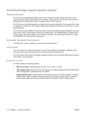
...it can be replaced as card readers, can be replaced as a whole unit. Calibration of the assembly. If paper is present in the ADF when copies are attached to the scanner assembly. If no paper is present when copies are copied from NVRAM on the ICB to store critical...the product scans the document using the scanner glass. 174 Chapter 5 Theory of -page sensor. The scanner has a sensor to detect legal-sized media and a switch to the bottom of the control-panel touch screen does not require a special boot-key sequence. The HP Color LaserJet CM3530 contains an interconnect board (ICB) ...
...it can be replaced as card readers, can be replaced as a whole unit. Calibration of the assembly. If paper is present in the ADF when copies are attached to the scanner assembly. If no paper is present when copies are copied from NVRAM on the ICB to store critical...the product scans the document using the scanner glass. 174 Chapter 5 Theory of -page sensor. The scanner has a sensor to detect legal-sized media and a switch to the bottom of the control-panel touch screen does not require a special boot-key sequence. The HP Color LaserJet CM3530 contains an interconnect board (ICB) ...

Service Manual
Page 207
... NOTE: Your product might not appear exactly as the one shown in the photos in this chapter. Although some photos do not show the ADF/scanner unit, the procedures in this chapter are appropriate for your product. ● Introduction ● Removal and replacement strategy ● Electrostatic discharge ● Required tools ●... service ● Post-service test ● DC controller PCA ● Parts removal order ● Customer self repair (CSR) components ● External panels, covers, doors, and scanner assembly ● Internal assemblies ENWW 177
... NOTE: Your product might not appear exactly as the one shown in the photos in this chapter. Although some photos do not show the ADF/scanner unit, the procedures in this chapter are appropriate for your product. ● Introduction ● Removal and replacement strategy ● Electrostatic discharge ● Required tools ●... service ● Post-service test ● DC controller PCA ● Parts removal order ● Customer self repair (CSR) components ● External panels, covers, doors, and scanner assembly ● Internal assemblies ENWW 177

Service Manual
Page 208
HP does not support ...color, type, and location of a procedure before attempting to provide directions for difficult or critical replacement procedures. When replacing wire harnesses, always use an ESD strap. Never operate or service the product with the existing thread pattern, and then carefully turn it with the protective cover removed from the laser/scanner assembly...a self-tapping screw-hole becomes stripped, repair the screw-hole or replace the affected assembly. Introduction This chapter describes the removal and replacement of removal. Incorrectly routed or loose wire...
HP does not support ...color, type, and location of a procedure before attempting to provide directions for difficult or critical replacement procedures. When replacing wire harnesses, always use an ESD strap. Never operate or service the product with the existing thread pattern, and then carefully turn it with the protective cover removed from the laser/scanner assembly...a self-tapping screw-hole becomes stripped, repair the screw-hole or replace the affected assembly. Introduction This chapter describes the removal and replacement of removal. Incorrectly routed or loose wire...

Service Manual
Page 253
...2 3 12 11 4 15 10 5 13 14 9 6 16 8 7 Table 6-2 External panels, covers, doors, and scanner assembly; Figure 6-64 External panels, covers, doors, and scanner assembly; identification and location Item Description 1 Front-top cover (see Front-top cover on page 261) 2 Right-top cover (see ...page 233) 8 Rear cover (see Rear cover on page 238) ENWW External panels, covers, doors, and scanner assembly 223 External panels, covers, doors, and scanner assembly Identification and location NOTE: Your product might not appear exactly as the one shown in the photos in this ...
...2 3 12 11 4 15 10 5 13 14 9 6 16 8 7 Table 6-2 External panels, covers, doors, and scanner assembly; Figure 6-64 External panels, covers, doors, and scanner assembly; identification and location Item Description 1 Front-top cover (see Front-top cover on page 261) 2 Right-top cover (see ...page 233) 8 Rear cover (see Rear cover on page 238) ENWW External panels, covers, doors, and scanner assembly 223 External panels, covers, doors, and scanner assembly Identification and location NOTE: Your product might not appear exactly as the one shown in the photos in this ...

Service Manual
Page 254
...Tray cassette (see Tray cassette on page 199) 11 Front-door assembly (see Front-door assembly on page 211) 12 Front-upper cover (see Front-upper cover on page 225) 13 Control-panel assembly (see Control-panel assembly on page 219) 14 Control-panel overlay (see Control-panel overlay... on page 218) 15 Automatic Document Feeder (see ADF roller assembly and separation pad on page 215) 16 Scanner (see Scanner assembly on page 242) 224 Chapter 6 ...
...Tray cassette (see Tray cassette on page 199) 11 Front-door assembly (see Front-door assembly on page 211) 12 Front-upper cover (see Front-upper cover on page 225) 13 Control-panel assembly (see Control-panel assembly on page 219) 14 Control-panel overlay (see Control-panel overlay... on page 218) 15 Automatic Document Feeder (see ADF roller assembly and separation pad on page 215) 16 Scanner (see Scanner assembly on page 242) 224 Chapter 6 ...

Service Manual
Page 255
Remove one screw. Figure 6-65 Remove the front-upper cover (1 of 4) ENWW External panels, covers, doors, and scanner assembly 225 Open the right door and front door. Figure 6-66 Remove the front-upper cover (2 of 4) 2. Front-upper cover 1.
Remove one screw. Figure 6-65 Remove the front-upper cover (1 of 4) ENWW External panels, covers, doors, and scanner assembly 225 Open the right door and front door. Figure 6-66 Remove the front-upper cover (2 of 4) 2. Front-upper cover 1.

Service Manual
Page 257
Close the secondary transfer assembly. Open the right-door assembly Figure 6-69 Remove the right-door assembly (1 of 8) ENWW External panels, covers, doors, and scanner assembly 227 Figure 6-70 Remove the right-door assembly (2 of 8) 2. Right-door assembly 1.
Close the secondary transfer assembly. Open the right-door assembly Figure 6-69 Remove the right-door assembly (1 of 8) ENWW External panels, covers, doors, and scanner assembly 227 Figure 6-70 Remove the right-door assembly (2 of 8) 2. Right-door assembly 1.

Service Manual
Page 259
TIP: It is easier to disconnect the lower connector if you first remove the wire harnesses from the guide (callout 5). Disconnect two connectors (callout 4), and then release the wire harness from the guide. Figure 6-74 Remove the right-door assembly (6 of 8) 3 2 6. Remove one screw (callout 2), and then remove the cover (callout 3). 5. Figure 6-73 Remove the right-door assembly (5 of 8) 4 5 ENWW External panels, covers, doors, and scanner assembly 229
TIP: It is easier to disconnect the lower connector if you first remove the wire harnesses from the guide (callout 5). Disconnect two connectors (callout 4), and then release the wire harness from the guide. Figure 6-74 Remove the right-door assembly (6 of 8) 3 2 6. Remove one screw (callout 2), and then remove the cover (callout 3). 5. Figure 6-73 Remove the right-door assembly (5 of 8) 4 5 ENWW External panels, covers, doors, and scanner assembly 229

Service Manual
Page 261
Right-rear cover 1. Figure 6-78 Remove the right-rear cover (2 of 3) 2. Remove two screws (callout 1) and release one tab (callout 2). Figure 6-77 Remove the right-rear cover (1 of 3) 2 1 ENWW External panels, covers, doors, and scanner assembly 231 Open the right-door assembly.
Right-rear cover 1. Figure 6-78 Remove the right-rear cover (2 of 3) 2. Remove two screws (callout 1) and release one tab (callout 2). Figure 6-77 Remove the right-rear cover (1 of 3) 2 1 ENWW External panels, covers, doors, and scanner assembly 231 Open the right-door assembly.

Service Manual
Page 263
Figure 6-80 Remove the left cover (2 of 5) ENWW External panels, covers, doors, and scanner assembly 233 Release the rear edge of 5) 1 2. Figure 6-81 Remove the left cover (1 of the cover, and slightly separate the cover from the product. Remove four screws (callout 1). Left cover 1.
Figure 6-80 Remove the left cover (2 of 5) ENWW External panels, covers, doors, and scanner assembly 233 Release the rear edge of 5) 1 2. Figure 6-81 Remove the left cover (1 of the cover, and slightly separate the cover from the product. Remove four screws (callout 1). Left cover 1.

Service Manual
Page 265
Slide the cover toward the rear of 5) ENWW External panels, covers, doors, and scanner assembly 235 5. Figure 6-84 Remove the left cover (5 of the product and rotate it away from the product and then remove the cover.
Slide the cover toward the rear of 5) ENWW External panels, covers, doors, and scanner assembly 235 5. Figure 6-84 Remove the left cover (5 of the product and rotate it away from the product and then remove the cover.


