
Service Manual
Page 13
... S, T, and U optional Tray 3 media-size sensors 407 Paper-path sensors test 408 Print/Stop test 409 Component tests 409 Component test (special mode test 409 Diagrams ...411 Formatter PCA 411 Location of connectors 412 DC controller PCA 412 Paper feeder driver PCA 413 PCAs, motors, fans, switches, solenoids, and clutches 414...
... S, T, and U optional Tray 3 media-size sensors 407 Paper-path sensors test 408 Print/Stop test 409 Component tests 409 Component test (special mode test 409 Diagrams ...411 Formatter PCA 411 Location of connectors 412 DC controller PCA 412 Paper feeder driver PCA 413 PCAs, motors, fans, switches, solenoids, and clutches 414...

Service Manual
Page 14
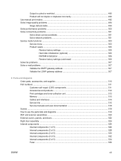
... Circuit diagrams 423 Print-quality troubleshooting tools 427 Repetitive defects ruler 428 Calibrate the product 430 Internal print-quality test pages 431 Print-quality-troubleshooting pages 431 Diagnostics page 434 Cleaning page 435 Configuration pages 436 Configuration page 436 HP embedded ...Jetdirect page 438 Embedded protocol page 439 Finding important information on the configuration pages 440 Color-band test 440 Control-panel messages ...441 Event log messages ...468 Print...
... Circuit diagrams 423 Print-quality troubleshooting tools 427 Repetitive defects ruler 428 Calibrate the product 430 Internal print-quality test pages 431 Print-quality-troubleshooting pages 431 Diagnostics page 434 Cleaning page 435 Configuration pages 436 Configuration page 436 HP embedded ...Jetdirect page 438 Embedded protocol page 439 Finding important information on the configuration pages 440 Color-band test 440 Control-panel messages ...441 Event log messages ...468 Print...
Service Manual
Page 15
... problems ...507 Solve e-mail problems ...507 Validate the SMTP gateway address 507 Validate the LDAP gateway address 507 8 Parts and diagrams Order parts, accessories, and supplies 510 Part numbers ...511 Customer self-repair (CSR) components 511 Accessories and products 512 Print cartridges... Cables and interfaces ...514 Service kits ...515 Service manuals and user documentation 518 Screws ...519 How to use the parts lists and diagrams 519 ADF and scanner assemblies ...520 External covers, panels, and doors 522 Right door assembly ...524 Internal components ...526 Internal components ...
... problems ...507 Solve e-mail problems ...507 Validate the SMTP gateway address 507 Validate the LDAP gateway address 507 8 Parts and diagrams Order parts, accessories, and supplies 510 Part numbers ...511 Customer self-repair (CSR) components 511 Accessories and products 512 Print cartridges... Cables and interfaces ...514 Service kits ...515 Service manuals and user documentation 518 Screws ...519 How to use the parts lists and diagrams 519 ADF and scanner assemblies ...520 External covers, panels, and doors 522 Right door assembly ...524 Internal components ...526 Internal components ...

Service Manual
Page 21
...item locations ...94 Figure 5-1 Relationship between the main product systems 116 Figure 5-2 Engine-control system ...118 Figure 5-3 DC controller block diagram ...119 Figure 5-4 High-voltage power supply circuits 123 Figure 5-5 Low-voltage power-supply circuit 125 Figure 5-6 Fuser (fixing) components... ...127 Figure 5-7 Fuser temperature-control circuit 128 Figure 5-8 Laser/scanner system ...131 Figure 5-9 Image-formation system ...133 Figure 5-10 Image-formation process ...134 Figure 5-11 Pre-exposure ...135 ...
...item locations ...94 Figure 5-1 Relationship between the main product systems 116 Figure 5-2 Engine-control system ...118 Figure 5-3 DC controller block diagram ...119 Figure 5-4 High-voltage power supply circuits 123 Figure 5-5 Low-voltage power-supply circuit 125 Figure 5-6 Fuser (fixing) components... ...127 Figure 5-7 Fuser temperature-control circuit 128 Figure 5-8 Laser/scanner system ...131 Figure 5-9 Image-formation system ...133 Figure 5-10 Image-formation process ...134 Figure 5-11 Pre-exposure ...135 ...

Service Manual
Page 30
...General timing chart ...423 Figure 7-38 General circuit diagram (1 of 2 424 Figure 7-39 General circuit diagram (2 of 2 425 Figure 7-40 Product circuit block diagram ...425 Figure 7-41 Paper feeder circuit diagram ...426 Figure 7-42 Repetitive defects ruler ...428 Figure... 7-43 Print-quality troubleshooting procedure 431 Figure 7-44 Yellow print-quality troubleshooting page 432 Figure 7-45 Yellow comparison page ...432 Figure 7-46 Black print-quality troubleshooting page 433 Figure 7-47 Configuration page ...436 Figure 7-48 HP...
...General timing chart ...423 Figure 7-38 General circuit diagram (1 of 2 424 Figure 7-39 General circuit diagram (2 of 2 425 Figure 7-40 Product circuit block diagram ...425 Figure 7-41 Paper feeder circuit diagram ...426 Figure 7-42 Repetitive defects ruler ...428 Figure... 7-43 Print-quality troubleshooting procedure 431 Figure 7-44 Yellow print-quality troubleshooting page 432 Figure 7-45 Yellow comparison page ...432 Figure 7-46 Black print-quality troubleshooting page 433 Figure 7-47 Configuration page ...436 Figure 7-48 HP...

Service Manual
Page 123
... to light for the best printing results. For more information about ordering supplies, see the product user guide. ENWW Manage supplies 93 To install a new HP print cartridge, see Parts and diagrams on page 94. To order supplies, see Change print cartridges on page 509. NOTE: Any damage caused by a non...
... to light for the best printing results. For more information about ordering supplies, see the product user guide. ENWW Manage supplies 93 To install a new HP print cartridge, see Parts and diagrams on page 94. To order supplies, see Change print cartridges on page 509. NOTE: Any damage caused by a non...

Service Manual
Page 149
DC controller The DC controller controls the operational sequence of the printer. Figure 5-3 DC controller block diagram Fuser Solenoids Table 5-2 Solenoids Component abbreviation SL1 SL2 SL3 SL4 Component name Primary transfer roller disengagement solenoid Duplex reverse solenoid Multipurpose-tray pickup solenoid Cassette pickup solenoid Laser/scanner ENWW Engine-control system 119
DC controller The DC controller controls the operational sequence of the printer. Figure 5-3 DC controller block diagram Fuser Solenoids Table 5-2 Solenoids Component abbreviation SL1 SL2 SL3 SL4 Component name Primary transfer roller disengagement solenoid Duplex reverse solenoid Multipurpose-tray pickup solenoid Cassette pickup solenoid Laser/scanner ENWW Engine-control system 119

Service Manual
Page 441
Diagrams Formatter PCA Figure 7-27 Formatter PCA 2 3 1 4 5 6 Table 7-6 Formatter PCA Item Description 1 Hard drive 2 Hard drive cable 3 DIMM slot (under the hard drive) 4 Fax card and cable 5 EIO slot 6 Internal USB ports ENWW Tools for troubleshooting 411
Diagrams Formatter PCA Figure 7-27 Formatter PCA 2 3 1 4 5 6 Table 7-6 Formatter PCA Item Description 1 Hard drive 2 Hard drive cable 3 DIMM slot (under the hard drive) 4 Fax card and cable 5 EIO slot 6 Internal USB ports ENWW Tools for troubleshooting 411

Service Manual
Page 444
PCAs, motors, fans, switches, solenoids, and clutches Use the diagrams to locate components. For a list of components, see Table 7-9 PCAs, motors, fans, switches, solenoids, and clutches on page 418 Base product Figure 7-30 Component locations (1 of 5) 1 414 Chapter 7 Solve problems ENWW
PCAs, motors, fans, switches, solenoids, and clutches Use the diagrams to locate components. For a list of components, see Table 7-9 PCAs, motors, fans, switches, solenoids, and clutches on page 418 Base product Figure 7-30 Component locations (1 of 5) 1 414 Chapter 7 Solve problems ENWW
Service Manual
Page 454
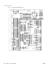
Circuit diagrams Figure 7-38 General circuit diagram (1 of 2) Fuser pressure release sensor Fuser delivery sensor 424 Chapter 7 Solve problems ENWW
Circuit diagrams Figure 7-38 General circuit diagram (1 of 2) Fuser pressure release sensor Fuser delivery sensor 424 Chapter 7 Solve problems ENWW

Service Manual
Page 455
Figure 7-39 General circuit diagram (2 of 2) Fuser motor ENWW Fuser Tools for troubleshooting 425
Figure 7-39 General circuit diagram (2 of 2) Fuser motor ENWW Fuser Tools for troubleshooting 425

Service Manual
Page 456
Figure 7-40 Product circuit block diagram ADF Control Panel Pocket 5v hub 12v to 5v USB + 12v Scanner ADF open/close switch Home position Motor Size Sensor Optics LED array Cave light FFC 5v PCI-E 24v 24v SCB Stapler Engine Formatter Backplane ICB FFC DCC LVPS 3.3v/5v AC 110/220v 426 Chapter 7 Solve problems ENWW
Figure 7-40 Product circuit block diagram ADF Control Panel Pocket 5v hub 12v to 5v USB + 12v Scanner ADF open/close switch Home position Motor Size Sensor Optics LED array Cave light FFC 5v PCI-E 24v 24v SCB Stapler Engine Formatter Backplane ICB FFC DCC LVPS 3.3v/5v AC 110/220v 426 Chapter 7 Solve problems ENWW

Service Manual
Page 539
8 Parts and diagrams ● Order parts, accessories, and supplies ● Part numbers ● Screws ● How to use the parts lists and diagrams ● ADF and scanner assemblies ● External covers, panels, and doors ● Right door assembly ● Internal components ● Accessories ● Alphabetical parts list ● Numerical parts list ENWW 509
8 Parts and diagrams ● Order parts, accessories, and supplies ● Part numbers ● Screws ● How to use the parts lists and diagrams ● ADF and scanner assemblies ● External covers, panels, and doors ● Right door assembly ● Internal components ● Accessories ● Alphabetical parts list ● Numerical parts list ENWW 509

Service Manual
Page 540
To order accessories, go to www.hp.com/go/hpparts/. Order parts, accessories, and supplies You can obtain the following items directly from HP: ● Replacement parts: To order replacement parts in the U.S., go to www.hp.com/ghp/buyonline.html. To order supplies worldwide, go to www.hp.com/go to www.hp.com/support/cljcm3530mfp. 510 Chapter 8 Parts and diagrams ENWW Outside the United States, order parts by contacting your local authorized HP service center. ● Supplies and accessories: To order supplies in the U.S., go /ljsupplies.
To order accessories, go to www.hp.com/go/hpparts/. Order parts, accessories, and supplies You can obtain the following items directly from HP: ● Replacement parts: To order replacement parts in the U.S., go to www.hp.com/ghp/buyonline.html. To order supplies worldwide, go to www.hp.com/go to www.hp.com/support/cljcm3530mfp. 510 Chapter 8 Parts and diagrams ENWW Outside the United States, order parts by contacting your local authorized HP service center. ● Supplies and accessories: To order supplies in the U.S., go /ljsupplies.

Service Manual
Page 544
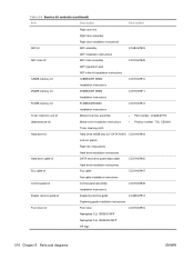
...-CORD OPT-920 3-COND 1.9-M- 8121-0729 LG ROHS Power cord India ( Cables and interfaces Table 8-5 Cables and interfaces Item Description Part number Enhanced I/O (EIO) card HP Jetdirect 635n IPv6/IPsec Print Server J7961G USB cable 2-meter standard USB-compatible device connector C6518A Power cord North America PWR-CORD OPT-903 3-COND...
...-CORD OPT-920 3-COND 1.9-M- 8121-0729 LG ROHS Power cord India ( Cables and interfaces Table 8-5 Cables and interfaces Item Description Part number Enhanced I/O (EIO) card HP Jetdirect 635n IPv6/IPsec Print Server J7961G USB cable 2-meter standard USB-compatible device connector C6518A Power cord North America PWR-CORD OPT-903 3-COND...
Service Manual
Page 546
...-67908 Installation instructions Duplex reverse guide kit Duplexing reverse guide CC468-67913 Duplexing guide installation instructions Front door kit Front door CC519-67916 Nameplate CLJ CM3530 MFP Nameplate CLJ CM3530fs MFP HP logo 516 Chapter 8 Parts and diagrams ENWW
...-67908 Installation instructions Duplex reverse guide kit Duplexing reverse guide CC468-67913 Duplexing guide installation instructions Front door kit Front door CC519-67916 Nameplate CLJ CM3530 MFP Nameplate CLJ CM3530fs MFP HP logo 516 Chapter 8 Parts and diagrams ENWW
Service Manual
Page 548
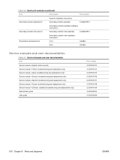
... guide Part number CC519-91013 CC519-91014 CC519-91015 CC519-91016 CC519-91017 CC519-91018 CC519-91019 CC519-60105 CC519-60106 518 Chapter 8 Parts and diagrams ENWW
... guide Part number CC519-91013 CC519-91014 CC519-91015 CC519-91016 CC519-91017 CC519-91018 CC519-91019 CC519-60105 CC519-60106 518 Chapter 8 Parts and diagrams ENWW

Service Manual
Page 549
...the table, then it is listed in the description column. Components described as cables and sensors. Screws might consist of each exploded view assembly diagram. Table 8-8 Common fasteners Example Description Size Part Number Screw, with washer M3x8 XA9-1420-000CN Screw, tapping, truss head M4x10 XB4-7401-005CN...Screw, tooth washer M3x6 M3x8 M4x6 XA9-1503-000CN XA9-1671-000CN XB2-7400-606CN 12 mm How to use the parts lists and diagrams The figures in this chapter show the major subassemblies in the following table are for reference only. NOTE: In this table. Each table ...
...the table, then it is listed in the description column. Components described as cables and sensors. Screws might consist of each exploded view assembly diagram. Table 8-8 Common fasteners Example Description Size Part Number Screw, with washer M3x8 XA9-1420-000CN Screw, tapping, truss head M4x10 XB4-7401-005CN...Screw, tooth washer M3x6 M3x8 M4x6 XA9-1503-000CN XA9-1671-000CN XB2-7400-606CN 12 mm How to use the parts lists and diagrams The figures in this chapter show the major subassemblies in the following table are for reference only. NOTE: In this table. Each table ...

Service Manual
Page 550
ADF and scanner assemblies Figure 8-1 ADF/scanner assembly 2 3 4 1 520 Chapter 8 Parts and diagrams ENWW
ADF and scanner assemblies Figure 8-1 ADF/scanner assembly 2 3 4 1 520 Chapter 8 Parts and diagrams ENWW

Service Manual
Page 552
External covers, panels, and doors Figure 8-2 External covers, panels, and doors 522 Chapter 8 Parts and diagrams ENWW
External covers, panels, and doors Figure 8-2 External covers, panels, and doors 522 Chapter 8 Parts and diagrams ENWW


