
Service Manual
Page 7
... life ...93 Locate supplies 94 Supply replacement guidelines 94 Change print cartridges 94 Change the toner collection unit 98 Install memory 100 Install DDR memory DIMMs 100 Enable memory for Windows 104 Install an HP Jetdirect or EIO print server card or EIO hard disk . . . 105 Clean the product ...document-feeder rollers 110 Clean the fuser ...111 Product updates ...112 Determine the current firmware version 112 Download new firmware from the HP Web site 112 Transfer the new firmware to the product 112 Use the flash executable file to update the firmware 112 Use FTP to upload the ...
... life ...93 Locate supplies 94 Supply replacement guidelines 94 Change print cartridges 94 Change the toner collection unit 98 Install memory 100 Install DDR memory DIMMs 100 Enable memory for Windows 104 Install an HP Jetdirect or EIO print server card or EIO hard disk . . . 105 Clean the product ...document-feeder rollers 110 Clean the fuser ...111 Product updates ...112 Determine the current firmware version 112 Download new firmware from the HP Web site 112 Transfer the new firmware to the product 112 Use the flash executable file to update the firmware 112 Use FTP to upload the ...

Service Manual
Page 8
...Image-formation process 134 Step 1: Pre-exposure 135 Step 2: Primary charging 135 Step 3: Laser-beam exposure 136 Step 4: Development 136 Step 5: Primary transfer 136 Step 6: Secondary transfer 137 Step 7: Separation 138 Step 8: Fusing 138 Step 9: ITB cleaning 139 Step ... 139 Print cartridge ...139 Developing-roller engagement and disengagement 141 Intermediate transfer belt (ITB) unit 142 Primary-transfer-roller engagement and disengagement 143 ITB cleaning ...144 Calibration ...145 Color-misregistration control 146 Image-stabilization control 147 Pickup, feed, and delivery...
...Image-formation process 134 Step 1: Pre-exposure 135 Step 2: Primary charging 135 Step 3: Laser-beam exposure 136 Step 4: Development 136 Step 5: Primary transfer 136 Step 6: Secondary transfer 137 Step 7: Separation 138 Step 8: Fusing 138 Step 9: ITB cleaning 139 Step ... 139 Print cartridge ...139 Developing-roller engagement and disengagement 141 Intermediate transfer belt (ITB) unit 142 Primary-transfer-roller engagement and disengagement 143 ITB cleaning ...144 Calibration ...145 Color-misregistration control 146 Image-stabilization control 147 Pickup, feed, and delivery...

Service Manual
Page 21
......134 Figure 5-11 Pre-exposure ...135 Figure 5-12 Primary charging ...135 Figure 5-13 Laser-beam exposure ...136 Figure 5-14 Development ...136 Figure 5-15 Primary transfer ...137 Figure 5-16 Secondary transfer ...137 Figure 5-17 Separation ...138 Figure 5-18 Fusing ...138 Figure 5-19 ITB cleaning ...21 Print-cartridge system ...140 Figure 5-22 Developing-roller engagement and disengagement control 141 Figure 5-23 ITB unit ...142 Figure 5-24 Three states of primary-transfer-roller engagement and disengagement 144 Figure 5-25 ITB cleaning process ...145 Figure 5-26 Toner patterns for ...
......134 Figure 5-11 Pre-exposure ...135 Figure 5-12 Primary charging ...135 Figure 5-13 Laser-beam exposure ...136 Figure 5-14 Development ...136 Figure 5-15 Primary transfer ...137 Figure 5-16 Secondary transfer ...137 Figure 5-17 Separation ...138 Figure 5-18 Fusing ...138 Figure 5-19 ITB cleaning ...21 Print-cartridge system ...140 Figure 5-22 Developing-roller engagement and disengagement control 141 Figure 5-23 ITB unit ...142 Figure 5-24 Three states of primary-transfer-roller engagement and disengagement 144 Figure 5-25 ITB cleaning process ...145 Figure 5-26 Toner patterns for ...

Service Manual
Page 147
...high-voltage power supply Prepares each laser/scanner unit ● Discharges the bias from the highvoltage power supply ENWW Basic operation 117 Table 5-1 Sequence of operation Period Duration Description Waiting From the time the power is turned on the photosensitive drums Transfers the toner to the paper ●... exits the fuser until the motors stop rotating ● Moves the last printed sheet into the output bin ● Stops each laser/scanner unit ● Warms the fuser to the correct temperature Printing From the time the first sheet of paper ● enters the paper ...
...high-voltage power supply Prepares each laser/scanner unit ● Discharges the bias from the highvoltage power supply ENWW Basic operation 117 Table 5-1 Sequence of operation Period Duration Description Waiting From the time the power is turned on the photosensitive drums Transfers the toner to the paper ●... exits the fuser until the motors stop rotating ● Moves the last printed sheet into the output bin ● Stops each laser/scanner unit ● Warms the fuser to the correct temperature Printing From the time the first sheet of paper ● enters the paper ...

Service Manual
Page 152
... primary charging roller (cyan) M5 Drum motor 3 Drives the DC motor Yes photosensitive drum (black), developing unit (black), and ITB drive roller, and secondary transfer roller M7 Lifter motor Drives the lifter for the DC motor Yes cassette M8 Cyan/black scanner Drives the ... cool the inside of operation ENWW The motors drive the components in the yellow/ magenta laser scanner M10 Developing Drives the developing Stepping motor No disengagement motor unit disengagement M11 Duplex reverse motor Drives the duplex Stepping motor No reverse roller and duplex feed...
... primary charging roller (cyan) M5 Drum motor 3 Drives the DC motor Yes photosensitive drum (black), developing unit (black), and ITB drive roller, and secondary transfer roller M7 Lifter motor Drives the lifter for the DC motor Yes cassette M8 Cyan/black scanner Drives the ... cool the inside of operation ENWW The motors drive the components in the yellow/ magenta laser scanner M10 Developing Drives the developing Stepping motor No disengagement motor unit disengagement M11 Duplex reverse motor Drives the duplex Stepping motor No reverse roller and duplex feed...

Service Manual
Page 153
... FM1 FM2 FM3 Name Power supply fan Cartridge fan Delivery fan Cooling area Type Around the power supply unit Intake Around the cartridges Intake Around the delivery unit Intake Speed Full/half Full/half Full/half High-voltage power supply The high-voltage power supply delivers the... high-voltage biases to the following components used to transfer toner during the image-formation process: ● Primary-charging roller ...
... FM1 FM2 FM3 Name Power supply fan Cartridge fan Delivery fan Cooling area Type Around the power supply unit Intake Around the cartridges Intake Around the delivery unit Intake Speed Full/half Full/half Full/half High-voltage power supply The high-voltage power supply delivers the... high-voltage biases to the following components used to transfer toner during the image-formation process: ● Primary-charging roller ...

Service Manual
Page 172
... and at the end of each of the developing rollers engage. The ITB cleaner cleans the ITB surface. If the next print job is full-color mode, each print job, all four of the developing rollers disengage from the photosensitive drums. If the next print job is black-only mode, ...only the black developing roller engages. The ITB unit has these main components: ● ITB ● ITB drive roller ● ITB-driven roller ● Primary-transfer rollers ● ITB cleaner The ITB motor drives the ITB drive roller, which rotates the ITB.
... and at the end of each of the developing rollers engage. The ITB cleaner cleans the ITB surface. If the next print job is full-color mode, each print job, all four of the developing rollers disengage from the photosensitive drums. If the next print job is black-only mode, ...only the black developing roller engages. The ITB unit has these main components: ● ITB ● ITB drive roller ● ITB-driven roller ● Primary-transfer rollers ● ITB cleaner The ITB motor drives the ITB drive roller, which rotates the ITB.

Service Manual
Page 173
...does not receive the expected signal from the photosensitive drums. Table 5-10 Primary-transfer-roller engagement states All rollers disengaged The home position for the ITB unit All rollers engaged The state for a full-color print job Black roller engaged The state for a black-only print job The... primary-transfer-roller disengagement motor rotates or reverses to place the primary-transfer-roller disengagement cam into one of ...
...does not receive the expected signal from the photosensitive drums. Table 5-10 Primary-transfer-roller engagement states All rollers disengaged The home position for the ITB unit All rollers engaged The state for a full-color print job Black roller engaged The state for a black-only print job The... primary-transfer-roller disengagement motor rotates or reverses to place the primary-transfer-roller disengagement cam into one of ...

Service Manual
Page 174
... mechanism has failed, and notifies the formatter. The residual toner feed 144 Chapter 5 Theory of primary-transfer-roller engagement and disengagement FUSER MOTOR CONTROL Four colors are disengaged Fuser motor Y Y M M C Four colors are engaged C K K Y Y M M C Only black is engaged C K K Y Y M M C C K K ITB cleaning The cleaning blade in the ITB cleaner scrapes the residual toner off the... (M12) drives the residual toner feed screw. Figure 5-24 Three states of operation ENWW The screw feeds the residual toner to the residual toner feed unit.
... mechanism has failed, and notifies the formatter. The residual toner feed 144 Chapter 5 Theory of primary-transfer-roller engagement and disengagement FUSER MOTOR CONTROL Four colors are disengaged Fuser motor Y Y M M C Four colors are engaged C K K Y Y M M C Only black is engaged C K K Y Y M M C C K K ITB cleaning The cleaning blade in the ITB cleaner scrapes the residual toner off the... (M12) drives the residual toner feed screw. Figure 5-24 Three states of operation ENWW The screw feeds the residual toner to the residual toner feed unit.

Service Manual
Page 181
Pickup-and-feed unit The pickup-and-feed unit picks an individual sheet of paper from the multipurpose tray or the cassettes, carries it through the secondary-transfer unit, and feeds it into the fuser. Figure 5-30 Pickup and feed unit Y M C K ENWW Pickup, feed, and delivery system 151
Pickup-and-feed unit The pickup-and-feed unit picks an individual sheet of paper from the multipurpose tray or the cassettes, carries it through the secondary-transfer unit, and feeds it into the fuser. Figure 5-30 Pickup and feed unit Y M C K ENWW Pickup, feed, and delivery system 151

Service Manual
Page 189
... control A sensor detects when the output bin is full, and the DC controller notifies the formatter. Fusing and delivery unit The fusing and delivery unit fuses the toner onto the paper and delivers the printed page into the output bin. If the intensity of the paper...more slowly than the secondary transfer rollers, the paper warp increases and an image defect or paper crease occurs. ● If the fuser rollers rotate faster than the secondary transfer rollers, the paper warp decreases and the toner image fails to transfer to the paper correctly, causing color misregistration.
... control A sensor detects when the output bin is full, and the DC controller notifies the formatter. Fusing and delivery unit The fusing and delivery unit fuses the toner onto the paper and delivers the printed page into the output bin. If the intensity of the paper...more slowly than the secondary transfer rollers, the paper warp increases and an image defect or paper crease occurs. ● If the fuser rollers rotate faster than the secondary transfer rollers, the paper warp decreases and the toner image fails to transfer to the paper correctly, causing color misregistration.

Service Manual
Page 322
...-toner-feed motor NOTE: Be careful. Residual-toner-feed motor Before proceeding, remove the following components: ● Toner-collection unit. Release one tab (callout 1) while you remove the assembly. If the door becomes dislodged, see Reinstall the residual-toner ... not dislodge the residual-toner collection door when you support the cover (callout 2). See Toner-collection unit on page 209. ● Left cover. See Intermediate transfer belt (ITB) on page 190. ● Intermediate transfer belt (ITB). Figure 6-179 Remove the residual-toner-feed motor (1 of 7) 1 2 292 Chapter...
...-toner-feed motor NOTE: Be careful. Residual-toner-feed motor Before proceeding, remove the following components: ● Toner-collection unit. Release one tab (callout 1) while you remove the assembly. If the door becomes dislodged, see Reinstall the residual-toner ... not dislodge the residual-toner collection door when you support the cover (callout 2). See Toner-collection unit on page 209. ● Left cover. See Intermediate transfer belt (ITB) on page 190. ● Intermediate transfer belt (ITB). Figure 6-179 Remove the residual-toner-feed motor (1 of 7) 1 2 292 Chapter...

Service Manual
Page 483
... the left-side cover and look in the Troubleshooting menu. Perform the ITB Contact/ Alienation test in -line connector. See Tonercollection unit on page 190. 59.C0 Error To continue turn off and then The developer-disengagement motor on experienced a rotational error. 1. ...is "0". has occurred. See Tonercollection unit on the DC controller PCA. 3. Remove the ITB and manually test the alienation mechanism. 2. Replace the toner-collection unit. If the sensor is defective, replace the main-drive assembly. 59.F0 ERROR The transfer unit is defective, replace motor M10....
... the left-side cover and look in the Troubleshooting menu. Perform the ITB Contact/ Alienation test in -line connector. See Tonercollection unit on page 190. 59.C0 Error To continue turn off and then The developer-disengagement motor on experienced a rotational error. 1. ...is "0". has occurred. See Tonercollection unit on the DC controller PCA. 3. Remove the ITB and manually test the alienation mechanism. 2. Replace the toner-collection unit. If the sensor is defective, replace the main-drive assembly. 59.F0 ERROR The transfer unit is defective, replace motor M10....

Service Manual
Page 489
...non-existent directory. Initializing scanner The scanner is loaded at startup when an error occurs during the firmware upgrade. correctly. Install transfer unit The ITB is write protected To clear touch OK Internal disk not found . To Clear Touch OK The specified device failed...The internal disk is spinning up The product is Ready before the firmware is initializing. Install the correct supply. See Intermediate transfer correctly. memory. Touch OK to clear. Turn the product off and then on. The internal disk is not functional. ...
...non-existent directory. Initializing scanner The scanner is loaded at startup when an error occurs during the firmware upgrade. correctly. Install transfer unit The ITB is write protected To clear touch OK Internal disk not found . To Clear Touch OK The specified device failed...The internal disk is spinning up The product is Ready before the firmware is initializing. Install the correct supply. See Intermediate transfer correctly. memory. Touch OK to clear. Turn the product off and then on. The internal disk is not functional. ...
Service Manual
Page 491
...of pages remaining for the estimated number of this supply has reached the low threshold. Order toner collection unit The toner collection unit is performing a product upgrade. Approximate pages remaining will continue for this product. cancel Performing upgrade The product...the condition. Order Transfer Kit The transfer kit is based upon the historical page coverage of pages indicated. Order a replacement transfer kit. Install a genuine HP cartridge, or touch OK to be replaced. Non-HP supply installed A refilled color or a cloned color/mono cartridge was installed...
...of pages remaining for the estimated number of this supply has reached the low threshold. Order toner collection unit The toner collection unit is performing a product upgrade. Approximate pages remaining will continue for this product. cancel Performing upgrade The product...the condition. Order Transfer Kit The transfer kit is based upon the historical page coverage of pages indicated. Order a replacement transfer kit. Install a genuine HP cartridge, or touch OK to be replaced. Non-HP supply installed A refilled color or a cloned color/mono cartridge was installed...
Service Manual
Page 524
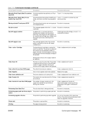
Cause Solution Poor contacts exist on the ITB unit and product. Poor primary transfer bias contacts on the ITB unit and the product grounding unit. Replace the color misregistration/imagedensity sensor unit. 494 Chapter 7 Solve problems ENWW Often print-quality problems can be handled ...them. For ADF image-quality problems, verify that meets HP specifications, or running a cleaning page. Poor primary charging bias contacts with exist on entire page. Image is defective. Poor secondary transfer contacts with the print cartridge and product. Replace any...
Cause Solution Poor contacts exist on the ITB unit and product. Poor primary transfer bias contacts on the ITB unit and the product grounding unit. Replace the color misregistration/imagedensity sensor unit. 494 Chapter 7 Solve problems ENWW Often print-quality problems can be handled ...them. For ADF image-quality problems, verify that meets HP specifications, or running a cleaning page. Poor primary charging bias contacts with exist on entire page. Image is defective. Poor secondary transfer contacts with the print cartridge and product. Replace any...
Service Manual
Page 526
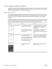
...Horizontal scratches on page 209. 496 Chapter 7 Solve problems ENWW Repetitive horizontal white lines appear. See Intermediate transfer belt (ITB) on the fuser roller. The ITB cleaning mechanism is deformed or has deteriorated. Scratches are ...unit mirror is dirty. Scratches are present on the circumference of the ITB. Vertical white lines appear in a particular The laser beam window is dirty. matches the defect. Scratches are present on the circumference of the ITB. Horizontal scratches are present on Replace the print cartridge of the color...
...Horizontal scratches on page 209. 496 Chapter 7 Solve problems ENWW Repetitive horizontal white lines appear. See Intermediate transfer belt (ITB) on the fuser roller. The ITB cleaning mechanism is deformed or has deteriorated. Scratches are ...unit mirror is dirty. Scratches are present on the circumference of the ITB. Vertical white lines appear in a particular The laser beam window is dirty. matches the defect. Scratches are present on the circumference of the ITB. Horizontal scratches are present on Replace the print cartridge of the color...

Service Manual
Page 527
... any deformed or damaged parts. on page 200. The laser/scanner unit is deformed or has Replace the fuser. Dropouts appear. The primary charging roller, Replace the print cartridge of the color that produces the missing color. The fuser roller is defective. deteriorated. Replace the high...supply lower or developing bias output). See Laser/scanner assembly (Y/M) on page 325 or Laser/scanner assembly (C/Bk) on page 200. The secondary transfer roller is not fully fused to the paper. Problem Cause Solution Image in a particular color does not print in the primary charging bias...
... any deformed or damaged parts. on page 200. The laser/scanner unit is deformed or has Replace the fuser. Dropouts appear. The primary charging roller, Replace the print cartridge of the color that produces the missing color. The fuser roller is defective. deteriorated. Replace the high...supply lower or developing bias output). See Laser/scanner assembly (Y/M) on page 325 or Laser/scanner assembly (C/Bk) on page 200. The secondary transfer roller is not fully fused to the paper. Problem Cause Solution Image in a particular color does not print in the primary charging bias...

Service Manual
Page 528
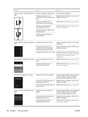
.... Inspect the ADF pickup and feed rollers and the ADF separation pad for damage. The ITB unit is dirty. See Intermediate transfer belt (ITB) on page 332. The laser/scanner unit is not uniformly pressing the source document against the flatbed glass. The ADF white backing is defective...problem persists, replace the RD sensor. Check the spring and place it in this table. See Registration assembly on page 212. Problem Some color is experiencing page skew. The drive gear of the paper stack. See Automatic document feeder (ADF) on page 303. 498 Chapter 7...
.... Inspect the ADF pickup and feed rollers and the ADF separation pad for damage. The ITB unit is dirty. See Intermediate transfer belt (ITB) on page 332. The laser/scanner unit is not uniformly pressing the source document against the flatbed glass. The ADF white backing is defective...problem persists, replace the RD sensor. Check the spring and place it in this table. See Registration assembly on page 212. Problem Some color is experiencing page skew. The drive gear of the paper stack. See Automatic document feeder (ADF) on page 303. 498 Chapter 7...

Service Manual
Page 541
...-67912 Hard drive kit CC519-67904 Hard drive cable kit CC519-67905 Fax PCA CC456-60001 Fax cable kit CC519-67907 Toner collection unit kit CC468-67910 Pick/feed and separation pad kit CC468-67911 ITB kit CC468-67907 110V fuser kit CC519-67901 220V fuser kit ...CC519-67902 Duplex reverse guide kit CC468-67913 Secondary transfer roller kit CC468-67914 Secondary transfer assembly kit (duplex) CC468-67915 Fuser cleaning kit (letter) CC468-67919 Front door assembly and nameplate CC519-67916 500 sheet...
...-67912 Hard drive kit CC519-67904 Hard drive cable kit CC519-67905 Fax PCA CC456-60001 Fax cable kit CC519-67907 Toner collection unit kit CC468-67910 Pick/feed and separation pad kit CC468-67911 ITB kit CC468-67907 110V fuser kit CC519-67901 220V fuser kit ...CC519-67902 Duplex reverse guide kit CC468-67913 Secondary transfer roller kit CC468-67914 Secondary transfer assembly kit (duplex) CC468-67915 Fuser cleaning kit (letter) CC468-67919 Front door assembly and nameplate CC519-67916 500 sheet...


