
HP Color LaserJet CM3530 MFP Series - User Guide
Page 221
...the product and print the document again. You are using paper that has already passed through a product Do not use paper that the transfer belt and transfer roller are worn. Adjust them so they hold the stack firmly in place without bending it over. The internal tray rollers are not ... removing it . Verify that the stack is heavier than 220 g/m2 (58 lb), it . NOTE: Internal areas of the product that meets HP specifications. ENWW Jams 207 The paper is loaded incorrectly. Paper was not stored correctly. Use only paper that might not be stored in the original...
...the product and print the document again. You are using paper that has already passed through a product Do not use paper that the transfer belt and transfer roller are worn. Adjust them so they hold the stack firmly in place without bending it over. The internal tray rollers are not ... removing it . Verify that the stack is heavier than 220 g/m2 (58 lb), it . NOTE: Internal areas of the product that meets HP specifications. ENWW Jams 207 The paper is loaded incorrectly. Paper was not stored correctly. Use only paper that might not be stored in the original...

Service Manual
Page 8
...Laser-beam exposure 136 Step 4: Development 136 Step 5: Primary transfer 136 Step 6: Secondary transfer 137 Step 7: Separation 138 Step 8: Fusing 138 Step 9: ITB cleaning 139 Step 10: Drum cleaning 139 Print cartridge ...139 Developing-roller engagement and disengagement 141 Intermediate transfer belt (ITB) unit 142 Primary-transfer...-roller engagement and disengagement 143 ITB cleaning ...144 Calibration ...145 Color-misregistration control 146 Image-stabilization control ...
...Laser-beam exposure 136 Step 4: Development 136 Step 5: Primary transfer 136 Step 6: Secondary transfer 137 Step 7: Separation 138 Step 8: Fusing 138 Step 9: ITB cleaning 139 Step 10: Drum cleaning 139 Print cartridge ...139 Developing-roller engagement and disengagement 141 Intermediate transfer belt (ITB) unit 142 Primary-transfer...-roller engagement and disengagement 143 ITB cleaning ...144 Calibration ...145 Color-misregistration control 146 Image-stabilization control ...
Service Manual
Page 10
... Fuser ...200 Pickup roller (Tray 2) ...201 Pickup and feed rollers (Tray 3 203 Separation roller (Tray 2 204 Secondary transfer roller 205 Reinstall the transfer roller 206 Secondary transfer assembly 207 Reinstall the secondary transfer assembly 208 Intermediate transfer belt (ITB 209 Front-door assembly ...211 Automatic document feeder (ADF 212 Calibrate a replacement ADF assembly 214 ADF roller...
... Fuser ...200 Pickup roller (Tray 2) ...201 Pickup and feed rollers (Tray 3 203 Separation roller (Tray 2 204 Secondary transfer roller 205 Reinstall the transfer roller 206 Secondary transfer assembly 207 Reinstall the secondary transfer assembly 208 Intermediate transfer belt (ITB 209 Front-door assembly ...211 Automatic document feeder (ADF 212 Calibrate a replacement ADF assembly 214 ADF roller...
Service Manual
Page 23
... (2 of 3 205 Remove the transfer roller (3 of 3 206 Reinstall the transfer roller ...206 Remove the transfer roller (2 of 3 207 Remove the secondary transfer assembly (1 of 2 207 Remove the secondary transfer assembly (2 of 2 208 Reinstall the secondary transfer assembly 208 Remove the intermediate transfer belt (1 of 3 209 Remove the intermediate transfer belt (2 of 3 209 Remove the intermediate transfer belt (3 of 3 210 Remove the...
... (2 of 3 205 Remove the transfer roller (3 of 3 206 Reinstall the transfer roller ...206 Remove the transfer roller (2 of 3 207 Remove the secondary transfer assembly (1 of 2 207 Remove the secondary transfer assembly (2 of 2 208 Reinstall the secondary transfer assembly 208 Remove the intermediate transfer belt (1 of 3 209 Remove the intermediate transfer belt (2 of 3 209 Remove the intermediate transfer belt (3 of 3 210 Remove the...

Service Manual
Page 172
If the next print job is full-color mode, each of the developing rollers engage. If the DC controller does not detect any output from the photosensitive drums and transfers the completed image to rotate. The motion of operation ENWW The ITB unit has these main components: ...which rotates the ITB. Figure 5-23 ITB unit Y M C K 142 Chapter 5 Theory of the ITB causes the primary transfer rollers to the paper. Intermediate transfer belt (ITB) unit The ITB unit accepts the toner images from the developing home-position sensor, it determines that the developing-disengagement ...
If the next print job is full-color mode, each of the developing rollers engage. If the DC controller does not detect any output from the photosensitive drums and transfers the completed image to rotate. The motion of operation ENWW The ITB unit has these main components: ...which rotates the ITB. Figure 5-23 ITB unit Y M C K 142 Chapter 5 Theory of the ITB causes the primary transfer rollers to the paper. Intermediate transfer belt (ITB) unit The ITB unit accepts the toner images from the developing home-position sensor, it determines that the developing-disengagement ...

Service Manual
Page 239
...-door assembly. 2. and left-side of 3) ENWW Customer self repair (CSR) components 209 Figure 6-42 Remove the intermediate transfer belt (2 of the ITB. Skin oils and fingerprints on the belt can cause printquality problems. Always place the ITB on the ITB and then pull the ITB out of 3) 1 3. Grasp... the small handles on a flat surface in a safe and protected location. 1. Figure 6-41 Remove the intermediate transfer belt (1 of the product until two large handles expand along the right- Intermediate transfer belt (ITB) CAUTION: Do not touch the black-plastic...
...-door assembly. 2. and left-side of 3) ENWW Customer self repair (CSR) components 209 Figure 6-42 Remove the intermediate transfer belt (2 of the ITB. Skin oils and fingerprints on the belt can cause printquality problems. Always place the ITB on the ITB and then pull the ITB out of 3) 1 3. Grasp... the small handles on a flat surface in a safe and protected location. 1. Figure 6-41 Remove the intermediate transfer belt (1 of the product until two large handles expand along the right- Intermediate transfer belt (ITB) CAUTION: Do not touch the black-plastic...

Service Manual
Page 240
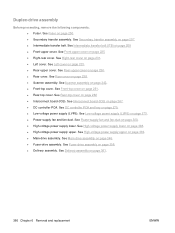
Grasp the large handles on the ITB and then pull the ITB straight out of the packing tape (callout 1) and the protective cover sheet (callout 2). 2 1 210 Chapter 6 Removal and replacement ENWW Figure 6-43 Remove the intermediate transfer belt (3 of 3) Reinstallation tip If you remove all of the product to remove it is a sensitive component. Be careful when handling the ITB so that you are installing a replacement ITB, make sure that it . Always place the ITB in a safe and protected location. CAUTION: The ITB is not damaged. 4.
Grasp the large handles on the ITB and then pull the ITB straight out of the packing tape (callout 1) and the protective cover sheet (callout 2). 2 1 210 Chapter 6 Removal and replacement ENWW Figure 6-43 Remove the intermediate transfer belt (3 of 3) Reinstallation tip If you remove all of the product to remove it is a sensitive component. Be careful when handling the ITB so that you are installing a replacement ITB, make sure that it . Always place the ITB in a safe and protected location. CAUTION: The ITB is not damaged. 4.

Service Manual
Page 322
.... Figure 6-179 Remove the residual-toner-feed motor (1 of 7) 1 2 292 Chapter 6 Removal and replacement ENWW See Intermediate transfer belt (ITB) on page 296 to reinstall it. 1. See Left cover on page 190. ● Intermediate transfer belt (ITB). Do not dislodge the residual-toner collection door when you support the cover (callout 2). See Toner-collection...
.... Figure 6-179 Remove the residual-toner-feed motor (1 of 7) 1 2 292 Chapter 6 Removal and replacement ENWW See Intermediate transfer belt (ITB) on page 296 to reinstall it. 1. See Left cover on page 190. ● Intermediate transfer belt (ITB). Do not dislodge the residual-toner collection door when you support the cover (callout 2). See Toner-collection...

Service Manual
Page 327
Remove two screws (callout 1). Keep the shutter in this position for the following components: ● Secondary transfer assembly. See Intermediate transfer belt (ITB) on page 207. ● Intermediate transfer belt (ITB). Remove the RD sensor assembly 1. Registration density (RD) sensor assembly Before proceeding, remove the following step. Figure 6-188 Remove the RD sensor assembly (2 of 6) 1 2. ...
Remove two screws (callout 1). Keep the shutter in this position for the following components: ● Secondary transfer assembly. See Intermediate transfer belt (ITB) on page 207. ● Intermediate transfer belt (ITB). Remove the RD sensor assembly 1. Registration density (RD) sensor assembly Before proceeding, remove the following step. Figure 6-188 Remove the RD sensor assembly (2 of 6) 1 2. ...

Service Manual
Page 333
... to reinstall the registration assembly. ● Power-supply fan and fan duct. See Rear-upper cover on page 209. ● Right-rear cover. See Intermediate transfer belt (ITB) on page 236. ● Registration density (RD) sensor assembly. See Power-supply fan and fan duct on page 231. ● Left cover. Figure... (1 of 8) 1 ENWW Internal assemblies 303 See Right-rear cover on page 300. See Registration density (RD) sensor assembly on page 207. ● Intermediate transfer belt (ITB). Registration assembly Before proceeding, remove the following components: ● Secondary...
... to reinstall the registration assembly. ● Power-supply fan and fan duct. See Rear-upper cover on page 209. ● Right-rear cover. See Intermediate transfer belt (ITB) on page 236. ● Registration density (RD) sensor assembly. See Power-supply fan and fan duct on page 231. ● Left cover. Figure... (1 of 8) 1 ENWW Internal assemblies 303 See Right-rear cover on page 300. See Registration density (RD) sensor assembly on page 207. ● Intermediate transfer belt (ITB). Registration assembly Before proceeding, remove the following components: ● Secondary...

Service Manual
Page 376
... screws (callout 1), and then remove the cover (callout 2). See Secondary transfer assembly on page 270. ● Low-voltage power supply (LVPS). See DC controller PCA and tray on page 207. ● Intermediate transfer belt (ITB). See Power-supply fan and fan duct on page 209. ●...; Right-rear cover. Main-drive assembly Before proceeding, remove the following components: ● Formatter PCA. See Intermediate transfer belt (ITB) on page 300. ● High-...
... screws (callout 1), and then remove the cover (callout 2). See Secondary transfer assembly on page 270. ● Low-voltage power supply (LVPS). See DC controller PCA and tray on page 207. ● Intermediate transfer belt (ITB). See Power-supply fan and fan duct on page 209. ●...; Right-rear cover. Main-drive assembly Before proceeding, remove the following components: ● Formatter PCA. See Intermediate transfer belt (ITB) on page 300. ● High-...
Service Manual
Page 396
See Intermediate transfer belt (ITB) on page 300. ● High-voltage power supply lower. See Power-supply fan and fan duct on page 209 ● Front-upper cover. See ... 308. ● High-voltage power supply upper. See Scanner assembly on page 207. ● Intermediate transfer belt. See Secondary transfer assembly on page 242. ● Front-top cover. See Interconnect board (ICB) on page 200. ● Secondary transfer assembly. See Fuser on page 267. ● DC controller PCA. See Rear cover on page 270...
See Intermediate transfer belt (ITB) on page 300. ● High-voltage power supply lower. See Power-supply fan and fan duct on page 209 ● Front-upper cover. See ... 308. ● High-voltage power supply upper. See Scanner assembly on page 207. ● Intermediate transfer belt. See Secondary transfer assembly on page 242. ● Front-top cover. See Interconnect board (ICB) on page 200. ● Secondary transfer assembly. See Fuser on page 267. ● DC controller PCA. See Rear cover on page 270...

Service Manual
Page 426
Open the right door. 2. Remove the ITB. 4. If the flag does not actuate, replace the ITB. Locate the sensor behind the cyan OPC drum position. 396 Chapter 7 Solve problems ENWW See Intermediate transfer belt (ITB) on page 209. Rotate the gear (callout 1) to move the flag (callout 2). Remove all removed print cartridges with paper. 6. NOTE: Cover all print cartridges. Lower the secondary transfer assembly. 3. I primary transfer-roller disengagement sensor 1. Figure 7-12 Test the primary transfer-roller disengagement sensor (1 of 2) 1 2 5.
Open the right door. 2. Remove the ITB. 4. If the flag does not actuate, replace the ITB. Locate the sensor behind the cyan OPC drum position. 396 Chapter 7 Solve problems ENWW See Intermediate transfer belt (ITB) on page 209. Rotate the gear (callout 1) to move the flag (callout 2). Remove all removed print cartridges with paper. 6. NOTE: Cover all print cartridges. Lower the secondary transfer assembly. 3. I primary transfer-roller disengagement sensor 1. Figure 7-12 Test the primary transfer-roller disengagement sensor (1 of 2) 1 2 5.

Service Manual
Page 439
... switch must be defeated to run . Touch Administration. 2. Scroll to recognize a change. This process continues for troubleshooting 409 CYAN LASER SCANNER M8 Activates the black/cyan scanner motor for 10 seconds. Print/Stop test Use this test you can be programmed to stop...Table 7-5 Component test details Component test Motor or solenoid number Comments TRANSFER MOTOR M5 BELT ONLY CARTRIDGE MOTOR M10 ● M3: yellow ● M4: magenta and cyan ● M5: black Rotates the transfer belt. BLACK LASER SCANNER M8 Activates the black/cyan scanner motor for 10 seconds. ...
... switch must be defeated to run . Touch Administration. 2. Scroll to recognize a change. This process continues for troubleshooting 409 CYAN LASER SCANNER M8 Activates the black/cyan scanner motor for 10 seconds. Print/Stop test Use this test you can be programmed to stop...Table 7-5 Component test details Component test Motor or solenoid number Comments TRANSFER MOTOR M5 BELT ONLY CARTRIDGE MOTOR M10 ● M3: yellow ● M4: magenta and cyan ● M5: black Rotates the transfer belt. BLACK LASER SCANNER M8 Activates the black/cyan scanner motor for 10 seconds. ...
Service Manual
Page 494
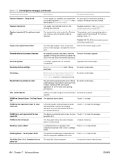
...panel messages (continued) Control panel message Description Recommended action Replace Supplies - See Intermediate transfer belt (ITB) on page 209. Replace transfer kit To continue, touch OK The transfer kit is necessary. print an internal page is necessary. To Clear Touch The ...Print Modes, Restore Optimization, or Restore Color Values operation is being performed. Initialize the device. Rotating Motor A component test is set to stop the test. item is in black. component selected is a motor. See Intermediate transfer belt (ITB) on page 209. RFU...
...panel messages (continued) Control panel message Description Recommended action Replace Supplies - See Intermediate transfer belt (ITB) on page 209. Replace transfer kit To continue, touch OK The transfer kit is necessary. print an internal page is necessary. To Clear Touch The ...Print Modes, Restore Optimization, or Restore Color Values operation is being performed. Initialize the device. Rotating Motor A component test is set to stop the test. item is in black. component selected is a motor. See Intermediate transfer belt (ITB) on page 209. RFU...

Service Manual
Page 502
... place without bending it settles into the input tray. Paper should be picked from the product. 472 Chapter 7 Solve problems ENWW Verify that meets HP specifications. or copier. Remove any excess paper from Tray 1. The input-tray guides are worn. Reload the paper into the output bin. Reset ... locks have been removed from the tray. You are using paper that has already passed through a product Do not use paper that the transfer belt and transfer roller are not picking up the paper. Adjust them so they hold the stack firmly in the trays. The paper is heavier than 220...
... place without bending it settles into the input tray. Paper should be picked from the product. 472 Chapter 7 Solve problems ENWW Verify that meets HP specifications. or copier. Remove any excess paper from Tray 1. The input-tray guides are worn. Reload the paper into the output bin. Reset ... locks have been removed from the tray. You are using paper that has already passed through a product Do not use paper that the transfer belt and transfer roller are not picking up the paper. Adjust them so they hold the stack firmly in the trays. The paper is heavier than 220...

Service Manual
Page 525
... cartridge and the product. Replace the ITB. Replace the secondary-transfer-roller. The back of the color that the source document is all black or solid color. The pressure roller is dirty. See ADF roller assembly and separation pad on page 209. See Intermediate transfer belt (ITB) on page 215. If the dirt does not...
... cartridge and the product. Replace the ITB. Replace the secondary-transfer-roller. The back of the color that the source document is all black or solid color. The pressure roller is dirty. See ADF roller assembly and separation pad on page 209. See Intermediate transfer belt (ITB) on page 215. If the dirt does not...
Service Manual
Page 526
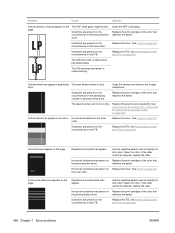
... the roller cannot be dirty. Replace the ITB. Replace the print cartridge of the color that the photosensitive drum. See Intermediate transfer belt (ITB) on page 209. Vertical white lines appear in a particular The laser beam window is malfunctioning. See Intermediate transfer belt (ITB) on page 209. Horizontal lines appear on page 200. matches the defect...
... the roller cannot be dirty. Replace the ITB. Replace the print cartridge of the color that the photosensitive drum. See Intermediate transfer belt (ITB) on page 209. Vertical white lines appear in a particular The laser beam window is malfunctioning. See Intermediate transfer belt (ITB) on page 209. Horizontal lines appear on page 200. matches the defect...

Service Manual
Page 528
... defective. The drive gear of the affected color. If the problem persists, replace the RD sensor. The laser/scanner unit is misregistered. Replace the print cartridge of the ITB motor is worn or chipped. Clean the grounding contacts on the printed page. ... row in the correct position. The product is defective. See the "Text or graphics are skewed on each print cartridge and the product. See Intermediate transfer belt (ITB) on the media. Poor grounding contacts exist between each drive gear between the ITB drive roller and the ITB motor. Check the ADF white...
... defective. The drive gear of the affected color. If the problem persists, replace the RD sensor. The laser/scanner unit is misregistered. Replace the print cartridge of the ITB motor is worn or chipped. Clean the grounding contacts on the printed page. ... row in the correct position. The product is defective. See the "Text or graphics are skewed on each print cartridge and the product. See Intermediate transfer belt (ITB) on the media. Poor grounding contacts exist between each drive gear between the ITB drive roller and the ITB motor. Check the ADF white...
Service Manual
Page 547
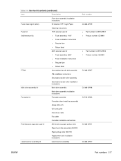
...HP Tough Paper Cleaning instructions Fuser kit (Maintenance kit) 110V service fuser kit ● Fuser assembly, 110V ● Fuser installation instructions ● Recycle flyer ● Return label 220V service fuser kit ● Fuser assembly, 220V ● Fuser installation instructions ● Recycle flyer ● Return label ITB kit Intermediate transfer belt... roller assembly (500 SF) Paper pickup roller (500 SF) Replacement and installation instructions Laser/scanner assembly kit Laser/scanner assembly Part number CC468-67919 ● Part number: CC519-67901 ● Product...
...HP Tough Paper Cleaning instructions Fuser kit (Maintenance kit) 110V service fuser kit ● Fuser assembly, 110V ● Fuser installation instructions ● Recycle flyer ● Return label 220V service fuser kit ● Fuser assembly, 220V ● Fuser installation instructions ● Recycle flyer ● Return label ITB kit Intermediate transfer belt... roller assembly (500 SF) Paper pickup roller (500 SF) Replacement and installation instructions Laser/scanner assembly kit Laser/scanner assembly Part number CC468-67919 ● Part number: CC519-67901 ● Product...


