HP Color LaserJet CM3530 Series - Software Technical Reference (external)
Page 254
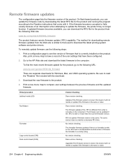
...3. If the firmware becomes corrupted or fails, usually because of the product. To remotely update firmware use the following URL: www.hp.com/go /cljcm3530mfp_firmware The product features remote firmware update (.RFU) capability. Print a new menu map to the computer. Does version...component. Also, print a menu map to have been configured. 2. Primary/Location Jetdirect inside (JDI) Fax Modem Formatter Copy control board (CPB) Scan control board (SCB) Version Checking Does version checking. Remote firmware updates The configuration page lists the firmware version of an ...
...3. If the firmware becomes corrupted or fails, usually because of the product. To remotely update firmware use the following URL: www.hp.com/go /cljcm3530mfp_firmware The product features remote firmware update (.RFU) capability. Print a new menu map to the computer. Does version...component. Also, print a menu map to have been configured. 2. Primary/Location Jetdirect inside (JDI) Fax Modem Formatter Copy control board (CPB) Scan control board (SCB) Version Checking Does version checking. Remote firmware updates The configuration page lists the firmware version of an ...
HP Color LaserJet CM3530 MFP Series - User Guide
Page 189
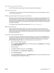
... settings. Select the product. 4. Select Security from gaining access to www.hp.com/go/webjetadmin/. Type a Device Password. 7. This prevents unauthorized users from changing the product configuration, you can install on the formatter board, in the EIO accessory slot, or in both locations. In the Control... Panel Access section, select Maximum Lock. Gain access to Secure Disk Erase Use HP Web Jetadmin to gain access to the control-panel ...
... settings. Select the product. 4. Select Security from gaining access to www.hp.com/go/webjetadmin/. Type a Device Password. 7. This prevents unauthorized users from changing the product configuration, you can install on the formatter board, in the EIO accessory slot, or in both locations. In the Control... Panel Access section, select Maximum Lock. Gain access to Secure Disk Erase Use HP Web Jetadmin to gain access to the control-panel ...

HP Color LaserJet CM3530 MFP Series - User Guide
Page 200
Disconnect all the cables. 3. 2. NOTE: This illustration might not show all power and interface cables. Place the formatter board on the formatter board in the rear of the product. 4. Locate the thumb screws on a clean, flat, grounded surface. 186 Chapter 13 Manage and maintain the product ENWW Unscrew the thumb screws and then pull the formatter board from the product.
Disconnect all the cables. 3. 2. NOTE: This illustration might not show all power and interface cables. Place the formatter board on the formatter board in the rear of the product. 4. Locate the thumb screws on a clean, flat, grounded surface. 186 Chapter 13 Manage and maintain the product ENWW Unscrew the thumb screws and then pull the formatter board from the product.

HP Color LaserJet CM3530 MFP Series - User Guide
Page 202
... the slot. NOTE: To prevent damage to the formatter board, ensure the formatter board is aligned with the bar in the tracks at the top and the bottom of the opening. 11. Push down on . 188 Chapter 13 Manage ... notch on the bottom of the DIMM is aligned in , make sure you are using the correct type of the slot, and then slide the board back into the product. 9.
... the slot. NOTE: To prevent damage to the formatter board, ensure the formatter board is aligned with the bar in the tracks at the top and the bottom of the opening. 11. Push down on . 188 Chapter 13 Manage ... notch on the bottom of the DIMM is aligned in , make sure you are using the correct type of the slot, and then slide the board back into the product. 9.

HP Color LaserJet CM3530 MFP Series - User Guide
Page 241
Unscrew the thumb screws and pull the formatter from the product. Disconnect all the cables. 3. ENWW Understand lights on the formatter board in the rear of the product. 4. NOTE: This illustration might not show all power and interface cables. Locate the thumb screws on the formatter 227 2.
Unscrew the thumb screws and pull the formatter from the product. Disconnect all the cables. 3. ENWW Understand lights on the formatter board in the rear of the product. 4. NOTE: This illustration might not show all power and interface cables. Locate the thumb screws on the formatter 227 2.

HP Color LaserJet CM3530 MFP Series - User Guide
Page 242
... still off, contact an HP-authorized service or support provider. Align the formatter board in the tracks at the bottom of the slot, and then slide the board back into the product. NOTE: To prevent damage to the formatter board, ensure the formatter board is functioning correctly. Heartbeat LED... The heartbeat LED indicates that the formatter is aligned in the tracks at the top and the bottom of the formatter to www.hp.com/support/cljcm3530mfp. 228 Chapter 14 ...
... still off, contact an HP-authorized service or support provider. Align the formatter board in the tracks at the bottom of the slot, and then slide the board back into the product. NOTE: To prevent damage to the formatter board, ensure the formatter board is functioning correctly. Heartbeat LED... The heartbeat LED indicates that the formatter is aligned in the tracks at the top and the bottom of the formatter to www.hp.com/support/cljcm3530mfp. 228 Chapter 14 ...

HP Color LaserJet CM3530 MFP Series - User Guide
Page 259
... with the HP Color LaserJet CM3530fs MFP model. Part numbers Ordering information and availability might change during the life of the product to handle large or complex print jobs. 128 MB 256 MB 512 MB CC409A CC410A CC411A HP Encrypted High Performance hard Internal encrypted hard disk to install on J8018A disks the formatter board 63 mm...
... with the HP Color LaserJet CM3530fs MFP model. Part numbers Ordering information and availability might change during the life of the product to handle large or complex print jobs. 128 MB 256 MB 512 MB CC409A CC410A CC411A HP Encrypted High Performance hard Internal encrypted hard disk to install on J8018A disks the formatter board 63 mm...
HP Color LaserJet CM3530 MFP Series - User Guide
Page 283
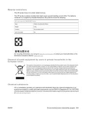
... in our products as REACH (Regulation EC No 1907/2006 of waste electrical and electronic equipment. This HP product contains a battery that this product include the following: HP Color LaserJet CM3530 MFP Series Type Carbon monofluoride lithium Weight 0.8 g Location On formatter board User-removable No For recycling information, you purchased the product. ENWW Environmental product stewardship program 269...
... in our products as REACH (Regulation EC No 1907/2006 of waste electrical and electronic equipment. This HP product contains a battery that this product include the following: HP Color LaserJet CM3530 MFP Series Type Carbon monofluoride lithium Weight 0.8 g Location On formatter board User-removable No For recycling information, you purchased the product. ENWW Environmental product stewardship program 269...

HP Color LaserJet CM3530 MFP Series - Analog Fax Accessory 500 Fax Guide
Page 59
...accessory is installed but the icon does not appear on page 50. Cause Solution HP MFP Digital Sending Software Configuration utility has disabled the analog-fax feature. The accessory is not displaying the fax menus. The MFP is not operating correctly. If the status is NON-OPERATIONAL, new firmware might ...card might need to be replaced. Check the fax accessory status, see Customer support on page 69. If the status is enabled. Faulty formatter board. Use the HP MFP Digital Sending Software Configuration utility to enable the analog-fax feature. Contact your...
...accessory is installed but the icon does not appear on page 50. Cause Solution HP MFP Digital Sending Software Configuration utility has disabled the analog-fax feature. The accessory is not displaying the fax menus. The MFP is not operating correctly. If the status is NON-OPERATIONAL, new firmware might ...card might need to be replaced. Check the fax accessory status, see Customer support on page 69. If the status is enabled. Faulty formatter board. Use the HP MFP Digital Sending Software Configuration utility to enable the analog-fax feature. Contact your...

Service Manual
Page 131
Disconnect all the cables. 3. Place the formatter board on the formatter board in the rear of the product. 4. Unscrew the thumb screws and then pull the formatter board from the product. ENWW Manage supplies 101 2. Locate the thumb screws on a clean, flat, grounded surface. NOTE: This illustration might not show all power and interface cables.
Disconnect all the cables. 3. Place the formatter board on the formatter board in the rear of the product. 4. Unscrew the thumb screws and then pull the formatter board from the product. ENWW Manage supplies 101 2. Locate the thumb screws on a clean, flat, grounded surface. NOTE: This illustration might not show all power and interface cables.

Service Manual
Page 133
ENWW Manage supplies 103 Align the formatter board in the slot. NOTE: To prevent damage to the formatter board, ensure the formatter board is aligned with the bar in the tracks at the top and the bottom of the slot, and then slide the board back into the product. XOXXOOXXOOXO XOXOXXOOXOXO XOXOXO XIOXIO XIOXIOXIXO XIOXIO XIOXIOXIXO XIOXIO XIOXIOXIXO...
ENWW Manage supplies 103 Align the formatter board in the slot. NOTE: To prevent damage to the formatter board, ensure the formatter board is aligned with the bar in the tracks at the top and the bottom of the slot, and then slide the board back into the product. XOXXOOXXOOXO XOXOXXOOXOXO XOXOXO XIOXIO XIOXIOXIXO XIOXIO XIOXIOXIXO XIOXIO XIOXIOXIXO...
Service Manual
Page 204
...the scanner fails, it can be replaced as a whole unit. The HP Color LaserJet CM3530 contains an interconnect board (ICB) which includes the frame, glass, LED optics, and a scanner controller board (SCB) attached to store critical engines values and formatter data. Automatic document feed system If the ADF fails, it can be ...to the scanner assembly. The ADF and control-panel assembly are copied from NVRAM on the ICB to the new component. When a formatter or DC controller is replaced, the critical engine values are attached to indicate when the ADF is present in the ADF when copies...
...the scanner fails, it can be replaced as a whole unit. The HP Color LaserJet CM3530 contains an interconnect board (ICB) which includes the frame, glass, LED optics, and a scanner controller board (SCB) attached to store critical engines values and formatter data. Automatic document feed system If the ADF fails, it can be ...to the scanner assembly. The ADF and control-panel assembly are copied from NVRAM on the ICB to the new component. When a formatter or DC controller is replaced, the critical engine values are attached to indicate when the ADF is present in the ADF when copies...

Service Manual
Page 297
Interconnect board (ICB) WARNING! HP recommends that if you remove and replace the ICB, you should destroy the discarded ICB so that product and cause it to be installed in a ... ICB NOTE: To locate DC controller connector locations, see DC controller PCA on page 236. ● Rear cover. Before proceeding, remove the following components: ● Formatter PCA. See Rear-upper cover on page 183. 1. J105), and then remove one connector (callouts 1; Do not remove the ICB from a product and then install...
Interconnect board (ICB) WARNING! HP recommends that if you remove and replace the ICB, you should destroy the discarded ICB so that product and cause it to be installed in a ... ICB NOTE: To locate DC controller connector locations, see DC controller PCA on page 236. ● Rear cover. Before proceeding, remove the following components: ● Formatter PCA. See Rear-upper cover on page 183. 1. J105), and then remove one connector (callouts 1; Do not remove the ICB from a product and then install...

Service Manual
Page 300
... 4) 2 1 270 Chapter 6 Removal and replacement ENWW Figure 6-141 Remove the DC controller PCA and tray (1 of 4) on page 267. See Interconnect board (ICB) on page 272. 1. Remove the DC controller PCA and tray CAUTION: ESD-sensitive part. TIP: To access components behind the DC controller PCA,... remove the PCA and the sheet-metal tray together. See Formatter PCA on page 236. ● Rear cover. See Rear-upper cover on page 192. ● Right-rear cover. Remove one screw (...
... 4) 2 1 270 Chapter 6 Removal and replacement ENWW Figure 6-141 Remove the DC controller PCA and tray (1 of 4) on page 267. See Interconnect board (ICB) on page 272. 1. Remove the DC controller PCA and tray CAUTION: ESD-sensitive part. TIP: To access components behind the DC controller PCA,... remove the PCA and the sheet-metal tray together. See Formatter PCA on page 236. ● Rear cover. See Rear-upper cover on page 192. ● Right-rear cover. Remove one screw (...

Service Manual
Page 303
...). See Rear cover on page 233. ● Rear-upper cover. See Interconnect board (ICB) on page 231. ● Left cover. NOTE: If you are removing the power supply for internal product access, it is recommended that you leave ... on page 192. ● Right-rear cover. NOTE: To locate DC controller connector locations, see DC controller PCA on the DC controller PCA). NOTE: The formatter cage is removed from the LVPS. 1. NOTE: If you leave the ICB installed on the power supply assembly. Low-voltage power supply (LVPS) Before proceeding...
...). See Rear cover on page 233. ● Rear-upper cover. See Interconnect board (ICB) on page 231. ● Left cover. NOTE: If you are removing the power supply for internal product access, it is recommended that you leave ... on page 192. ● Right-rear cover. NOTE: To locate DC controller connector locations, see DC controller PCA on the DC controller PCA). NOTE: The formatter cage is removed from the LVPS. 1. NOTE: If you leave the ICB installed on the power supply assembly. Low-voltage power supply (LVPS) Before proceeding...

Service Manual
Page 338
...-upper cover. Disconnect two connectors (callout 1), and then remove three screws (callout 2). See Rear-upper cover on page 238. ● Interconnect board (ICB). Remove the high-voltage power supply lower CAUTION: ESD-sensitive part. 1. See Rear cover on page 236. ● Rear cover. See...supply (LVPS) on page 192. ● Right-rear cover. High-voltage power supply lower Before proceeding, remove the following components: ● Formatter PCA. TIP: For internal product access, you can remove the ICB and the low-voltage power supply as a single component. ● Low...
...-upper cover. Disconnect two connectors (callout 1), and then remove three screws (callout 2). See Rear-upper cover on page 238. ● Interconnect board (ICB). Remove the high-voltage power supply lower CAUTION: ESD-sensitive part. 1. See Rear cover on page 236. ● Rear cover. See...supply (LVPS) on page 192. ● Right-rear cover. High-voltage power supply lower Before proceeding, remove the following components: ● Formatter PCA. TIP: For internal product access, you can remove the ICB and the low-voltage power supply as a single component. ● Low...

Service Manual
Page 341
... 273. ● High-voltage power supply lower. See Low-voltage power supply (LVPS) on page 308. Remove the developing-disengagement motor 1. See Formatter PCA on page 238. ● Interconnect board (ICB). See Rear cover on page 192. ● Right-rear cover. Figure 6-210 Remove the developing-disengagement motor (1 of 2) 1 ENWW Internal assemblies...
... 273. ● High-voltage power supply lower. See Low-voltage power supply (LVPS) on page 308. Remove the developing-disengagement motor 1. See Formatter PCA on page 238. ● Interconnect board (ICB). See Rear cover on page 192. ● Right-rear cover. Figure 6-210 Remove the developing-disengagement motor (1 of 2) 1 ENWW Internal assemblies...

Service Manual
Page 343
Figure 6-212 Remove the pickup motor 1 2 ENWW Internal assemblies 313 Pickup motor Before proceeding, remove the following components: ● Formatter PCA. See High-voltage power supply lower on page 236. ● Rear cover. TIP: For internal product access, you can remove the ICB ...motor. See Low-voltage power supply (LVPS) on page 192. ● Right-rear cover. See Formatter PCA on page 273. ● High-voltage power supply lower. See Right-rear cover on page 238. ● Interconnect board (ICB). See Rear cover on page 231. ● Left cover. See Left cover on page...
Figure 6-212 Remove the pickup motor 1 2 ENWW Internal assemblies 313 Pickup motor Before proceeding, remove the following components: ● Formatter PCA. See High-voltage power supply lower on page 236. ● Rear cover. TIP: For internal product access, you can remove the ICB ...motor. See Low-voltage power supply (LVPS) on page 192. ● Right-rear cover. See Formatter PCA on page 273. ● High-voltage power supply lower. See Right-rear cover on page 238. ● Interconnect board (ICB). See Rear cover on page 231. ● Left cover. See Left cover on page...

Service Manual
Page 344
Lifter-drive assembly Before proceeding, remove the following components: ● Formatter PCA. See Formatter PCA on page 238. ● Interconnect board (ICB). TIP: For internal product access, you can remove the ICB and the low-voltage power supply as a single component. ● Low-...on page 308. See Left cover on page 236. ● Rear cover. See Rear-upper cover on page 233. ● Rear-upper cover. See Interconnect board (ICB) on page 273. ● High-voltage power supply lower. Figure 6-213 Remove the lifter-drive assembly (1 of 2) 1 314 Chapter 6 Removal and...
Lifter-drive assembly Before proceeding, remove the following components: ● Formatter PCA. See Formatter PCA on page 238. ● Interconnect board (ICB). TIP: For internal product access, you can remove the ICB and the low-voltage power supply as a single component. ● Low-...on page 308. See Left cover on page 236. ● Rear cover. See Rear-upper cover on page 233. ● Rear-upper cover. See Interconnect board (ICB) on page 273. ● High-voltage power supply lower. Figure 6-213 Remove the lifter-drive assembly (1 of 2) 1 314 Chapter 6 Removal and...
Service Manual
Page 534
... grace period is reset to the result. When you perform a cold reset, the paper size that is YYDDD. Restore the service ID If you replace a formatter board in NVRAM is built into the installation date as follows: 2002 - 1990 = 12. LETTER and A4 are the only available values. To calculate YY, subtract..., the date conversion is as the standard paper size, use the product Service ID number to get 10, which represents October. 3. If you replace the formatter, the date is the month. 3.
... grace period is reset to the result. When you perform a cold reset, the paper size that is YYDDD. Restore the service ID If you replace a formatter board in NVRAM is built into the installation date as follows: 2002 - 1990 = 12. LETTER and A4 are the only available values. To calculate YY, subtract..., the date conversion is as the standard paper size, use the product Service ID number to get 10, which represents October. 3. If you replace the formatter, the date is the month. 3.


