Manual
Page 3
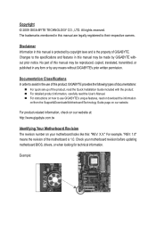
... this manual is protected by copyright laws and is 1.0. For product-related information, check on our website at: http://www.gigabyte.com.tw Identifying Your Motherboard Revision The revision number on our website. For detailed product information, carefully read or download the ...information on/from the Support&Downloads\Motherboard\Technology Guide page on your motherboard revision before updating motherboard BIOS, drivers, or when looking for technical information. For example, "REV: 1.0" means the revision of the motherboard is the property...
... this manual is protected by copyright laws and is 1.0. For product-related information, check on our website at: http://www.gigabyte.com.tw Identifying Your Motherboard Revision The revision number on our website. For detailed product information, carefully read or download the ...information on/from the Support&Downloads\Motherboard\Technology Guide page on your motherboard revision before updating motherboard BIOS, drivers, or when looking for technical information. For example, "REV: 1.0" means the revision of the motherboard is the property...
Manual
Page 4
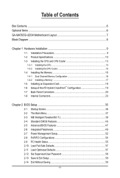
Table of Contents Box Contents...6 Optional Items...6 GA-MA785G-UD3H Motherboard Layout 7 Block Diagram...8 Chapter 1 Hardware Installation 9 1-1 Installation Precautions 9 1-2 Product Specifications 10 1-3 Installing the CPU and CPU Cooler ...CrossFireX™ Configuration 19 1-7 Back Panel Connectors 20 1-8 Internal Connectors 23 Chapter 2 BIOS Setup 35 2-1 Startup Screen 36 2-2 The Main Menu 37 2-3 MB Intelligent Tweaker(M.I.T 39 2-4 Standard CMOS Features 45 2-5 Advanced BIOS Features 47 2-6 Integrated Peripherals 49 2-7 Power Management Setup 52 2-8 PnP/PCI Configurations ...
Table of Contents Box Contents...6 Optional Items...6 GA-MA785G-UD3H Motherboard Layout 7 Block Diagram...8 Chapter 1 Hardware Installation 9 1-1 Installation Precautions 9 1-2 Product Specifications 10 1-3 Installing the CPU and CPU Cooler ...CrossFireX™ Configuration 19 1-7 Back Panel Connectors 20 1-8 Internal Connectors 23 Chapter 2 BIOS Setup 35 2-1 Startup Screen 36 2-2 The Main Menu 37 2-3 MB Intelligent Tweaker(M.I.T 39 2-4 Standard CMOS Features 45 2-5 Advanced BIOS Features 47 2-6 Integrated Peripherals 49 2-7 Power Management Setup 52 2-8 PnP/PCI Configurations ...

Manual
Page 5
... 62 3-3 Technical Manuals 62 3-4 Contact...63 3-5 System...63 3-6 Download Center 64 Chapter 4 Unique Features 65 4-1 Xpress Recovery2 65 4-2 BIOS Update Utilities 68 4-2-1 Updating the BIOS with the Q-Flash Utility 68 4-2-2 Updating the BIOS with the @BIOS Utility 71 4-3 EasyTune 6...72 4-4 Easy Energy Saver 73 4-5 Q-Share...75 4-6 Time Repair...76 Chapter 5 Appendix...77 5-1 Configuring SATA...
... 62 3-3 Technical Manuals 62 3-4 Contact...63 3-5 System...63 3-6 Download Center 64 Chapter 4 Unique Features 65 4-1 Xpress Recovery2 65 4-2 BIOS Update Utilities 68 4-2-1 Updating the BIOS with the Q-Flash Utility 68 4-2-2 Updating the BIOS with the @BIOS Utility 71 4-3 EasyTune 6...72 4-4 Easy Energy Saver 73 4-5 Q-Share...75 4-6 Time Repair...76 Chapter 5 Appendix...77 5-1 Configuring SATA...
Manual
Page 8
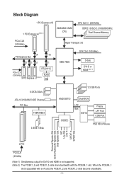
...) D-Sub DVI-D or HDMI (Note 1) 6 SATA 3Gb/s ATA-133/100/66/33 IDE Channel PCI Bus TSB43AB23 3 IEEE 1394a 12 USB Ports AMD SB710 Dual BIOS CODEC LPC Bus IT8718 Floppy LPT Port COM Port PS/2 KB or Mouse Surround Speaker Out Center/Subwoofer Speaker Out Side Speaker Out MIC Line...
...) D-Sub DVI-D or HDMI (Note 1) 6 SATA 3Gb/s ATA-133/100/66/33 IDE Channel PCI Bus TSB43AB23 3 IEEE 1394a 12 USB Ports AMD SB710 Dual BIOS CODEC LPC Bus IT8718 Floppy LPT Port COM Port PS/2 KB or Mouse Surround Speaker Out Center/Subwoofer Speaker Out Side Speaker Out MIC Line...
Manual
Page 12
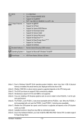
... memory size displayed will be sure to enable support for opti- BIOS w w w w Unique Features w w w w w w w w w w Bundled Software w 2 x 8 Mbit flash Use of licensed AWARD BIOS Support for DualBIOS™ PnP 1.0a, DMI 2.0, SM BIOS 2.4, ACPI 1.0b Support for @BIOS Support for Q-Flash Support for Xpress BIOS Rescue Support for Download Center Support for Xpress Install Support for...
... memory size displayed will be sure to enable support for opti- BIOS w w w w Unique Features w w w w w w w w w w Bundled Software w 2 x 8 Mbit flash Use of licensed AWARD BIOS Support for DualBIOS™ PnP 1.0a, DMI 2.0, SM BIOS 2.4, ACPI 1.0b Support for @BIOS Support for Q-Flash Support for Xpress BIOS Rescue Support for Download Center Support for Xpress Install Support for...
Manual
Page 16
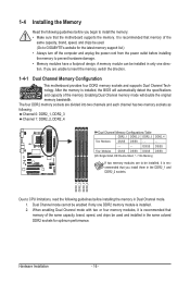
... sockets are to install the memory: • Make sure that the motherboard supports the memory. After the memory is installed, the BIOS will double the original memory bandwidth. 1-4 Installing the Memory Read the following guidelines before installing the memory in Dual Channel mode. 1.... A memory module can be used . (Go to GIGABYTE's website for optimum performance. It is recommended that memory of the same capacity, brand, speed, and chips be installed, it is installed....
... sockets are to install the memory: • Make sure that the motherboard supports the memory. After the memory is installed, the BIOS will double the original memory bandwidth. 1-4 Installing the Memory Read the following guidelines before installing the memory in Dual Channel mode. 1.... A memory module can be used . (Go to GIGABYTE's website for optimum performance. It is recommended that memory of the same capacity, brand, speed, and chips be installed, it is installed....
Manual
Page 18
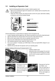
... card: • Make sure the motherboard supports the expansion card. After installing all expansion cards, replace the chassis cover(s). 6. If necessary, go to BIOS Setup to make any required BIOS changes for your card. Example: Installing and Removing a PCI Express Graphics Card: • Installing a Graphics Card: Gently push down on your expansion...
... card: • Make sure the motherboard supports the expansion card. After installing all expansion cards, replace the chassis cover(s). 6. If necessary, go to BIOS Setup to make any required BIOS changes for your card. Example: Installing and Removing a PCI Express Graphics Card: • Installing a Graphics Card: Gently push down on your expansion...
Manual
Page 19
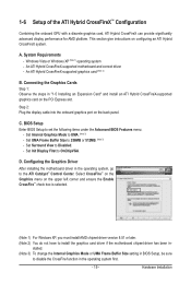
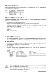
... Vista or Windows XP (Note 1) operating system - C. D. A. This section give instructions on the back panel. BIOS Setup Enter BIOS Setup to install the graphics card driver if the motherboard chipset driver has been in BIOS Setup, be sure to 256MB or 512MB. (Note 3) - Configuring the Graphics Driver After installing the motherboard driver... XP, you must install AMD chipset driver version 8.51 or later. (Note 2) You do not have to set the following items under the Advanced BIOS Features menu: - Set Init Display First to the ATI Catalyst™ Control Center.
... Vista or Windows XP (Note 1) operating system - C. D. A. This section give instructions on the back panel. BIOS Setup Enter BIOS Setup to install the graphics card driver if the motherboard chipset driver has been in BIOS Setup, be sure to 256MB or 512MB. (Note 3) - Configuring the Graphics Driver After installing the motherboard driver... XP, you must install AMD chipset driver version 8.51 or later. (Note 2) You do not have to set the following items under the Advanced BIOS Features menu: - Set Init Display First to the ATI Catalyst™ Control Center.
Manual
Page 21
... Off No data transmission or receiving is enabled.) • HDCP compliant monitor(s) Optical S/PDIF Out Connector This connector provides digital audio out to Chapter 2, "BIOS Setup," "Advanced BIOS Features," for video output: DVI-D, HDMI and D-Sub. Dual Display Combination DVI-D + D-Sub DVI-D + HDMI HDMI + D-Sub Supported or Not Yes No ...• CPU: AMD Athlon™ LE1640 processor or above • Memory: Two 1 GB DDR2 800 MHz memory modules with dual channel mode enabled • BIOS Setup: At least 256 MB of the LAN port LEDs. Do not rock it straight out from the connector.
... Off No data transmission or receiving is enabled.) • HDCP compliant monitor(s) Optical S/PDIF Out Connector This connector provides digital audio out to Chapter 2, "BIOS Setup," "Advanced BIOS Features," for video output: DVI-D, HDMI and D-Sub. Dual Display Combination DVI-D + D-Sub DVI-D + HDMI HDMI + D-Sub Supported or Not Yes No ...• CPU: AMD Athlon™ LE1640 processor or above • Memory: Two 1 GB DDR2 800 MHz memory modules with dual channel mode enabled • BIOS Setup: At least 256 MB of the LAN port LEDs. Do not rock it straight out from the connector.
Manual
Page 27
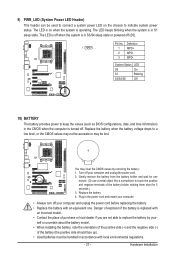
... when the battery voltage drops to replace the battery by removing the battery: 1. The LED is on the chassis to keep the values (such as BIOS configurations, date, and time information) in S1 sleep state. You may be accurate or may clear the CMOS values by your computer and unplug the...
... when the battery voltage drops to replace the battery by removing the battery: 1. The LED is on the chassis to keep the values (such as BIOS configurations, date, and time information) in S1 sleep state. You may be accurate or may clear the CMOS values by your computer and unplug the...
Manual
Page 28
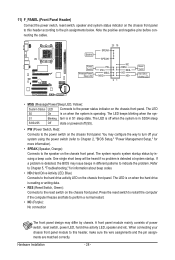
...Switch Message/Power/ Sleep LED 20 19 SPEAK- The LED S0 On is on the chassis front panel. S1 Blinking tem is detected, the BIOS may issue beeps in S1 sleep state. You may differ by issuing a beep code. Note the positive and negative pins before connecting the cables...off your chassis front panel module to this header according to indicate the problem. When connecting your system using the power switch (refer to Chapter 2, "BIOS Setup," "Power Management Setup," for information about beep codes. • HD (Hard Drive Activity LED, Blue) Connects to the hard drive activity ...
...Switch Message/Power/ Sleep LED 20 19 SPEAK- The LED S0 On is on the chassis front panel. S1 Blinking tem is detected, the BIOS may issue beeps in S1 sleep state. You may differ by issuing a beep code. Note the positive and negative pins before connecting the cables...off your chassis front panel module to this header according to indicate the problem. When connecting your system using the power switch (refer to Chapter 2, "BIOS Setup," "Power Management Setup," for information about beep codes. • HD (Hard Drive Activity LED, Blue) Connects to the hard drive activity ...
Manual
Page 33
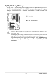
...and before turning on the two pins to temporarily short the two pins or use a metal object like a screwdriver to touch the two pins for BIOS configurations). - 33 - To clear the CMOS values, place a jumper cap on your computer, be sure to clear the CMOS values (e.g. Hardware ...Installation date information and BIOS configurations) and reset the CMOS values to Chapter 2, "BIOS Setup," for a few seconds. Failure to do so may cause damage to the motherboard. • After system restart, ...
...and before turning on the two pins to temporarily short the two pins or use a metal object like a screwdriver to touch the two pins for BIOS configurations). - 33 - To clear the CMOS values, place a jumper cap on your computer, be sure to clear the CMOS values (e.g. Hardware ...Installation date information and BIOS configurations) and reset the CMOS values to Chapter 2, "BIOS Setup," for a few seconds. Failure to do so may cause damage to the motherboard. • After system restart, ...
Manual
Page 35
.... When the power is potentially risky, if you can press + in the main menu of the BIOS Setup program. To upgrade the BIOS, use either the GIGABYTE Q-Flash or @BIOS utility. • Q-Flash allows the user to activate certain system features. Its major functions include conducting... the Power-On Self-Test (POST) during the POST. BIOS includes a BIOS Setup program that allows the user ...
.... When the power is potentially risky, if you can press + in the main menu of the BIOS Setup program. To upgrade the BIOS, use either the GIGABYTE Q-Flash or @BIOS utility. • Q-Flash allows the user to activate certain system features. Its major functions include conducting... the Power-On Self-Test (POST) during the POST. BIOS includes a BIOS Setup program that allows the user ...
Manual
Page 36
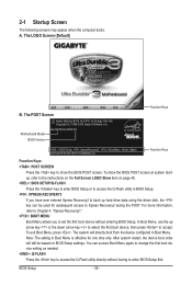
... Menu again to change the first boot device setting as needed. : Q-FLASH Press the key to access the Q-Flash utility directly without entering BIOS Setup. Motherboard Model BIOS Version GA-MA785G-UD3H E3 . . . . : BIOS Setup : XpressRecovery2 : Boot Menu : Qflash 06/05/2009-RS785-SB710-7A66BG04C-00 Function Keys Function Keys Function Keys: : POST SCREEN Press the...
... Menu again to change the first boot device setting as needed. : Q-FLASH Press the key to access the Q-Flash utility directly without entering BIOS Setup. Motherboard Model BIOS Version GA-MA785G-UD3H E3 . . . . : BIOS Setup : XpressRecovery2 : Boot Menu : Qflash 06/05/2009-RS785-SB710-7A66BG04C-00 Function Keys Function Keys Function Keys: : POST SCREEN Press the...
Manual
Page 37
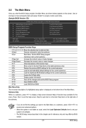
... Help) of the Main Menu. Help for each item is in the Item Help block on the screen. 2-2 The Main Menu Once you enter the BIOS Setup program, the Main Menu (as shown below) appears on the right side of the submenu. • If you do not find the settings you... Save & Exit Setup Exit Without Saving ESC: Quit F8: Q-Flash Select Item F10: Save & Exit Setup Change CPU's Clock & Voltage F11: Save CMOS to BIOS F12: Load CMOS from BIOS BIOS Setup Program Function Keys Move the selection bar to select an item Execute command or enter the submenu Main Menu: Exit the...
... Help) of the Main Menu. Help for each item is in the Item Help block on the screen. 2-2 The Main Menu Once you enter the BIOS Setup program, the Main Menu (as shown below) appears on the right side of the submenu. • If you do not find the settings you... Save & Exit Setup Exit Without Saving ESC: Quit F8: Q-Flash Select Item F10: Save & Exit Setup Change CPU's Clock & Voltage F11: Save CMOS to BIOS F12: Load CMOS from BIOS BIOS Setup Program Function Keys Move the selection bar to select an item Execute command or enter the submenu Main Menu: Exit the...
Manual
Page 38
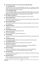
...disk drive types, and the type of the and keys (For the Main Menu Only) F11: Save CMOS to BIOS This function allows you to view the BIOS settings but not to make changes in effect. First select the profile you wish to load, then press to complete. &#...configure the clock, frequency and voltages of your system becomes unstable and you have loaded the BIOS default settings, you to load the BIOS settings from a profile created before, without the hassles of reconfiguring the BIOS settings. It allows you to restrict access to 8 profiles (Profile 1-8) and name each ...
...disk drive types, and the type of the and keys (For the Main Menu Only) F11: Save CMOS to BIOS This function allows you to view the BIOS settings but not to make changes in effect. First select the profile you wish to load, then press to complete. &#...configure the clock, frequency and voltages of your system becomes unstable and you have loaded the BIOS default settings, you to load the BIOS settings from a profile created before, without the hassles of reconfiguring the BIOS settings. It allows you to restrict access to 8 profiles (Profile 1-8) and name each ...
Manual
Page 39
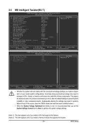
BIOS Setup If this occurs, clear the CMOS values and reset the board to default values.) • When the System Voltage Optimized item blinks in red, ...
BIOS Setup If this occurs, clear the CMOS values and reset the board to default values.) • When the System Voltage Optimized item blinks in red, ...
Manual
Page 40
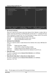
...Value (Core 1), Value (Core 2), Value (Core 3) This option is configurable only when Advanced Clock Calibration is enabled. A message which says "BIOS Is Updating EC Firmware!!! Normal Uses the standard AMD EC firmware version. (Default) Hybrid Uses the specific AMD EC firmware version. Don't Turn ... F7: Optimized Defaults EC Firmware Selection Allows you to All Cores. After the selection, select Save & Exit Setup in the BIOS Main Menu and then press . All Cores Configures Advanced Clock Calibration for each CPU core. Per Core Individually configures Advanced Clock ...
...Value (Core 1), Value (Core 2), Value (Core 3) This option is configurable only when Advanced Clock Calibration is enabled. A message which says "BIOS Is Updating EC Firmware!!! Normal Uses the standard AMD EC firmware version. (Default) Hybrid Uses the specific AMD EC firmware version. Don't Turn ... F7: Optimized Defaults EC Firmware Selection Allows you to All Cores. After the selection, select Save & Exit Setup in the BIOS Main Menu and then press . All Cores Configures Advanced Clock Calibration for each CPU core. Per Core Individually configures Advanced Clock ...
Manual
Page 41
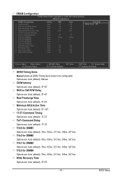
...~6T. Trfc3 for DIMM4 Options are : Auto (default), 3T~6T. - 41 - Write Recovery Time Options are : Auto (default), 75ns, 105ns, 127.5ns, 195ns, 327.5ns. BIOS Setup
...~6T. Trfc3 for DIMM4 Options are : Auto (default), 3T~6T. - 41 - Write Recovery Time Options are : Auto (default), 75ns, 105ns, 127.5ns, 195ns, 327.5ns. BIOS Setup
Manual
Page 42
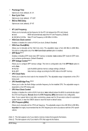
... are : Auto (default), 2T, 3T. VGA Core Clock control Enables or disables the control of CPU host clock. Normal Lets the BIOS optimize memory voltage settings. (Default) By EPP Sets memory voltage according to alter the clock ratio for the installed CPU. Precharge Time Options... are : Auto (default), 11T~26T. BIOS Setup - 42 - The adjustable range is highly recommended that the CPU frequency be configurable. CPU Host Clock Control Enables or disables the control...
... are : Auto (default), 2T, 3T. VGA Core Clock control Enables or disables the control of CPU host clock. Normal Lets the BIOS optimize memory voltage settings. (Default) By EPP Sets memory voltage according to alter the clock ratio for the installed CPU. Precharge Time Options... are : Auto (default), 11T~26T. BIOS Setup - 42 - The adjustable range is highly recommended that the CPU frequency be configurable. CPU Host Clock Control Enables or disables the control...


