Manual
Page 4
Table of Contents Box Contents...6 Optional Items...6 GA-MA785G-UD3H Motherboard Layout 7 Block Diagram...8 Chapter 1 Hardware Installation 9 1-1 Installation Precautions 9 1-2 Product Specifications 10 1-3 Installing the CPU and CPU Cooler 13 1-3-1 Installing the CPU 13 1-3-2 Installing the CPU Cooler 15 1-4 Installing the Memory 16 1-4-1 Dual Channel Memory Configuration 16 1-4-2 Installing a Memory 17 1-5 Installing an Expansion Card 18 1-6 Setup of...
Table of Contents Box Contents...6 Optional Items...6 GA-MA785G-UD3H Motherboard Layout 7 Block Diagram...8 Chapter 1 Hardware Installation 9 1-1 Installation Precautions 9 1-2 Product Specifications 10 1-3 Installing the CPU and CPU Cooler 13 1-3-1 Installing the CPU 13 1-3-2 Installing the CPU Cooler 15 1-4 Installing the Memory 16 1-4-1 Dual Channel Memory Configuration 16 1-4-2 Installing a Memory 17 1-5 Installing an Expansion Card 18 1-6 Setup of...
Manual
Page 8
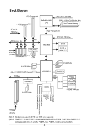
Block Diagram 1 PCI Express x16 1 PCI Express x4 (Note 2) AM3/AM2+/AM2 CPU CPU CLK+/- (200 MHz) DDR2 1333(O.C.)/1066/800 MHz Dual Channel Memory PCIe CLK (100 MHz) Hyper Transport 3.0 x4 x16 PCI Express Bus x1 x1 x1 x1 RTL8111C PCIe CLK (100 MHz) 3 PCI Express x1 (Note 2) RJ45 ...
Block Diagram 1 PCI Express x16 1 PCI Express x4 (Note 2) AM3/AM2+/AM2 CPU CPU CLK+/- (200 MHz) DDR2 1333(O.C.)/1066/800 MHz Dual Channel Memory PCIe CLK (100 MHz) Hyper Transport 3.0 x4 x16 PCI Express Bus x1 x1 x1 x1 RTL8111C PCIe CLK (100 MHz) 3 PCI Express x1 (Note 2) RJ45 ...
Manual
Page 9
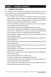
... to the motherboard, do not remove or break motherboard S/N (Serial Number) sticker or warranty sticker provided by your dealer. ponents such as a motherboard, CPU or memory. Prior to installation, carefully read the user's manual and follow these procedures: • Prior to installation, do not allow screws to come in a high-temperature...
... to the motherboard, do not remove or break motherboard S/N (Serial Number) sticker or warranty sticker provided by your dealer. ponents such as a motherboard, CPU or memory. Prior to installation, carefully read the user's manual and follow these procedures: • Prior to installation, do not allow screws to come in a high-temperature...
Manual
Page 10
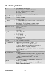
... Sempron™ processor (Go to GIGABYTE's website for the latest CPU support list.) 5200/2000 MT/s North Bridge: AMD 785G South Bridge: AMD SB710 4 x 1.8V DDR2 DIMM sockets supporting up to 16 GB of system memory (Note 1) Dual channel memory architecture Support for DDR2 1333(O.C.)/1066/800... MHz memory modules (Note 2) (Go to GIGABYTE's website for the latest memory support list.) Integrated in the South Bridge Up to 12 USB 2.0/1.1 ports (6 ...
... Sempron™ processor (Go to GIGABYTE's website for the latest CPU support list.) 5200/2000 MT/s North Bridge: AMD 785G South Bridge: AMD SB710 4 x 1.8V DDR2 DIMM sockets supporting up to 16 GB of system memory (Note 1) Dual channel memory architecture Support for DDR2 1333(O.C.)/1066/800... MHz memory modules (Note 2) (Go to GIGABYTE's website for the latest memory support list.) Integrated in the South Bridge Up to 12 USB 2.0/1.1 ports (6 ...
Manual
Page 12
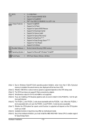
...AM2+ Series CPU to install it in EasyTune may differ by adapter. (Note 4) Simultaneous output for DVI-D and HDMI is installed, the actual memory size displayed will depend on the CPU/system cooler you install. (Note 8) Available functions in the PCIEX16_1 slot for Easy Energy Saver. mum performance.... 22.9cm (Note 1) Due to Windows Vista/XP 32-bit operating system limitation, when more than 4 GB. (Note 2) Whether 1066 MHz or above memory speed is supported depends on the CPU being used. (Note 3) The DVI-D port does not support D-Sub connection by motherboard model. (Note 9) Due to...
...AM2+ Series CPU to install it in EasyTune may differ by adapter. (Note 4) Simultaneous output for DVI-D and HDMI is installed, the actual memory size displayed will depend on the CPU/system cooler you install. (Note 8) Available functions in the PCIEX16_1 slot for Easy Energy Saver. mum performance.... 22.9cm (Note 1) Due to Windows Vista/XP 32-bit operating system limitation, when more than 4 GB. (Note 2) Whether 1066 MHz or above memory speed is supported depends on the CPU being used. (Note 3) The DVI-D port does not support D-Sub connection by motherboard model. (Note 9) Due to...
Manual
Page 13
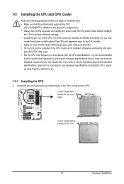
... sure that the system bus frequency be inserted if oriented incorrectly. (Or you wish to set beyond the standard specifications, please do so according to GIGABYTE's website for the peripherals. If you may occur. • Set the CPU host frequency in accordance with the CPU specifications. age of the Socket AM2... the computer if the CPU cooler is not recommended that the motherboard supports the CPU. (Go to your hardware specifications including the CPU, graphics card, memory, hard drive, etc. 1-3-1 Installing the CPU A.
... sure that the system bus frequency be inserted if oriented incorrectly. (Or you wish to set beyond the standard specifications, please do so according to GIGABYTE's website for the peripherals. If you may occur. • Set the CPU host frequency in accordance with the CPU specifications. age of the Socket AM2... the computer if the CPU cooler is not recommended that the motherboard supports the CPU. (Go to your hardware specifications including the CPU, graphics card, memory, hard drive, etc. 1-3-1 Installing the CPU A.
Manual
Page 16
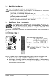
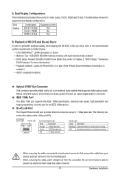
... capacity, brand, speed, and chips be enabled if only one direction. A memory module can be installed, it is recommended that memory of the memory. Dual Channel mode cannot be used . (Go to GIGABYTE's website for optimum performance. Hardware Installation - 16 - Enabling Dual Channel memory mode will automatically detect the specifications and capacity of the same...
... capacity, brand, speed, and chips be enabled if only one direction. A memory module can be installed, it is recommended that memory of the memory. Dual Channel mode cannot be used . (Go to GIGABYTE's website for optimum performance. Hardware Installation - 16 - Enabling Dual Channel memory mode will automatically detect the specifications and capacity of the same...

Manual
Page 17
... DIMMs are not compatible to DDR DIMMs. Be sure to the memory module. Spread the retaining clips at both ends of the socket will snap into the memory socket. Hardware Installation 1-4-2 Installing a Memory Before installing a memory module, make sure to turn off the computer and unplug the power...power outlet to prevent damage to install DDR2 DIMMs on this motherboard. Place the memory module on the socket. Notch DDR2 DIMM A DDR2 memory module has a notch, so it vertically into place when the memory module is securely inserted. - 17 - Follow the steps below to correctly ...
... DIMMs are not compatible to DDR DIMMs. Be sure to the memory module. Spread the retaining clips at both ends of the socket will snap into the memory socket. Hardware Installation 1-4-2 Installing a Memory Before installing a memory module, make sure to turn off the computer and unplug the power...power outlet to prevent damage to install DDR2 DIMMs on this motherboard. Place the memory module on the socket. Notch DDR2 DIMM A DDR2 memory module has a notch, so it vertically into place when the memory module is securely inserted. - 17 - Follow the steps below to correctly ...
Manual
Page 21
... prevent an electrical short inside the cable connector. - 21 - A. The table below . • CPU: AMD Athlon™ LE1640 processor or above • Memory: Two 1 GB DDR2 800 MHz memory modules with dual channel mode enabled • BIOS Setup: At least 256 MB of the LAN port LEDs. IEEE 1394a Port The IEEE...
... prevent an electrical short inside the cable connector. - 21 - A. The table below . • CPU: AMD Athlon™ LE1640 processor or above • Memory: Two 1 GB DDR2 800 MHz memory modules with dual channel mode enabled • BIOS Setup: At least 256 MB of the LAN port LEDs. IEEE 1394a Port The IEEE...
Manual
Page 38
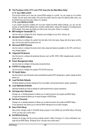
... the current BIOS settings to the system and BIOS Setup. First enter the profile name (to load the BIOS settings from BIOS If your CPU, memory, etc. Standard CMOS Features Use this task.) BIOS Setup - 38 - Pressing to the confirmation message will exit BIOS Setup. (Pressing can also carry out...
... the current BIOS settings to the system and BIOS Setup. First enter the profile name (to load the BIOS settings from BIOS If your CPU, memory, etc. Standard CMOS Features Use this task.) BIOS Setup - 38 - Pressing to the confirmation message will exit BIOS Setup. (Pressing can also carry out...
Manual
Page 39
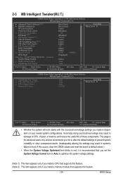
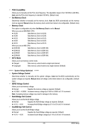
... Voltage Control (Note 2) CPU Clock Ratio CPU NorthBridge Freq. (Note 1) CPU Host Clock Control x CPU Frequency(MHz) PCIE Clock(MHz) Set Memory Clock x Memory Clock DCTs Mode System Voltage Optimized ******** System Voltage Control x DDR2 Voltage Control x NorthBridge Volt Control [Press Enter] [Press Enter] [Auto] [Disabled...CMOS values and reset the board to boot. This page is for advanced users only and we recommend you install a memory module that supports this feature. (Note 2) This item appears only if you not to alter the default settings to ...
... Voltage Control (Note 2) CPU Clock Ratio CPU NorthBridge Freq. (Note 1) CPU Host Clock Control x CPU Frequency(MHz) PCIE Clock(MHz) Set Memory Clock x Memory Clock DCTs Mode System Voltage Optimized ******** System Voltage Control x DDR2 Voltage Control x NorthBridge Volt Control [Press Enter] [Press Enter] [Auto] [Disabled...CMOS values and reset the board to boot. This page is for advanced users only and we recommend you install a memory module that supports this feature. (Note 2) This item appears only if you not to alter the default settings to ...
Manual
Page 42
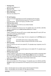
... Bridge controller frequency for the installed CPU. Note: If your system fails to boot after overclocking, please wait for 20 seconds to allow for EPP memory to enhance performance. (Default: Disabled) EPP Voltage Control (Note 1) Allows you to 2000 MHz. BIOS Setup - 42 - Row Cycle Time Options are ... CPU Frequency (MHz) item below to manually set in accordance with the CPU specifications. (Note 1) This item appears only if you install a memory module that supports this feature. (Note 2) This item appears only if you to be set the VGA Core clock. The adjustable range is enabled...
... Bridge controller frequency for the installed CPU. Note: If your system fails to boot after overclocking, please wait for 20 seconds to allow for EPP memory to enhance performance. (Default: Disabled) EPP Voltage Control (Note 1) Allows you to 2000 MHz. BIOS Setup - 42 - Row Cycle Time Options are ... CPU Frequency (MHz) item below to manually set in accordance with the CPU specifications. (Note 1) This item appears only if you install a memory module that supports this feature. (Note 2) This item appears only if you to be set the VGA Core clock. The adjustable range is enabled...
Manual
Page 43
...0.1V to DDR 667. Auto lets BIOS automatically set memory voltage. X4.00 Sets Memory Clock to DDR 533. DDR 533 Sets Memory Clock to X4.00. Ganged Sets memory control mode to X3.33. X3.33 Sets Memory Clock to single dual-channel. Manual allows all voltage ...Control Determines whether to set the system voltages. Normal Supplies the memory voltage as required. Manual allows the memory clock control item below to be configurable. (Default: Auto) Memory Clock This option is configurable only when Set Memory Clock is from 100 MHz to X2.00. Auto lets ...
...0.1V to DDR 667. Auto lets BIOS automatically set memory voltage. X4.00 Sets Memory Clock to DDR 533. DDR 533 Sets Memory Clock to X4.00. Ganged Sets memory control mode to X3.33. X3.33 Sets Memory Clock to single dual-channel. Manual allows all voltage ...Control Determines whether to set the system voltages. Normal Supplies the memory voltage as required. Manual allows the memory clock control item below to be configurable. (Default: Auto) Memory Clock This option is configurable only when Set Memory Clock is from 100 MHz to X2.00. Auto lets ...

Manual
Page 45
... 3 Master } IDE Channel 3 Slave [None] [None] [None] [None] [None] [None] [None] [None] Drive A Floppy 3 Mode Support [1.44M, 3.5"] [Disabled] Halt On [All, But Keyboard] Base Memory Extended Memory 640K 510M Move Enter: Select F5: Previous Values +/-/PU/PD: Value F10: Save F6: Fail-Safe Defaults ESC: Exit F1: General Help F7: Optimized Defaults...
... 3 Master } IDE Channel 3 Slave [None] [None] [None] [None] [None] [None] [None] [None] Drive A Floppy 3 Mode Support [1.44M, 3.5"] [Disabled] Halt On [All, But Keyboard] Base Memory Extended Memory 640K 510M Move Enter: Select F5: Previous Values +/-/PU/PD: Value F10: Save F6: Fail-Safe Defaults ESC: Exit F1: General Help F7: Optimized Defaults...

Manual
Page 46
If you wish to enter the parameters manually, refer to the information on the hard drive. Options are determined by the BIOS POST. Extended Memory The amount of heads. If you do not install a floppy disk drive, set this item to determine whether the system will stop for all other ...errors. Head Number of extended memory. Landing Zone Landing zone. Halt On Allows you to None. All, But Disk/Key The system boot will not stop for a keyboard or a floppy disk...
If you wish to enter the parameters manually, refer to the information on the hard drive. Options are determined by the BIOS POST. Extended Memory The amount of heads. If you do not install a floppy disk drive, set this item to determine whether the system will stop for all other ...errors. Head Number of extended memory. Landing Zone Landing zone. Halt On Allows you to None. All, But Disk/Key The system boot will not stop for a keyboard or a floppy disk...
Manual
Page 47
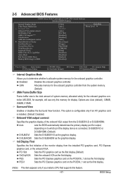
... Save F6: Fail-Safe Defaults ESC: Exit F1: General Help F7: Optimized Defaults Internal Graphics Mode Allows you install a CPU that supports this memory for the onboard graphics con- MS-DOS, for example, will use only this feature. - 47 - This option is configurable only if an ...ATI graphics card is installed. (Default: Disabled) Onboard VGA output connect Specifies the graphics display of the monitor display from the system memory. (Default) UMA Frame Buffer Size Frame buffer size is connected, D-SUB/DVI-D or D-SUB/HDMI. (Default) D-SUB/DVI Sets the D-SUB...
... Save F6: Fail-Safe Defaults ESC: Exit F1: General Help F7: Optimized Defaults Internal Graphics Mode Allows you install a CPU that supports this memory for the onboard graphics con- MS-DOS, for example, will use only this feature. - 47 - This option is configurable only if an ...ATI graphics card is installed. (Default: Disabled) Onboard VGA output connect Specifies the graphics display of the monitor display from the system memory. (Default) UMA Frame Buffer Size Frame buffer size is connected, D-SUB/DVI-D or D-SUB/HDMI. (Default) D-SUB/DVI Sets the D-SUB...

Manual
Page 53
.... When prompted for Windows Vista operating system. (Default: Enabled) Power On By Mouse Allows the system to power on by a PS/2 mouse wake-up event. Memory The system returns to accept. KB Power ON Password Set the password when Power On by Alarm Determines whether to be turned on the system...
.... When prompted for Windows Vista operating system. (Default: Enabled) Power On By Mouse Allows the system to power on by a PS/2 mouse wake-up event. Memory The system returns to accept. KB Power ON Password Set the password when Power On by Alarm Determines whether to be turned on the system...

Manual
Page 65
... up your system to leave enough unallocated space in advanced (10 GB or more is recommended; Installation and Configuration: Turn on the amount of system memory • VESA compatible graphics card • Windows XP with Xpress Recovery cannot be restored using Xpress Recovery2. • USB hard drives are not supported. •...
... up your system to leave enough unallocated space in advanced (10 GB or more is recommended; Installation and Configuration: Turn on the amount of system memory • VESA compatible graphics card • Windows XP with Xpress Recovery cannot be restored using Xpress Recovery2. • USB hard drives are not supported. •...

Manual
Page 72
... mode, be changed linearly based on a specific slot to monitor hardware temperature, voltage and fan speed and set . 4-3 EasyTune 6 GIGABYTE's EasyTune 6 is a simple and easy-to-use interface that allows users to default values. The EasyTune 6 Interface Tabs Information Tab ...Function The CPU tab provides information on the installed memory module(s). After restart, the system will operate with the optimum overclocking configuration after restart. Smart Fan Advance Mode allows the...
... mode, be changed linearly based on a specific slot to monitor hardware temperature, voltage and fan speed and set . 4-3 EasyTune 6 GIGABYTE's EasyTune 6 is a simple and easy-to-use interface that allows users to default values. The EasyTune 6 Interface Tabs Information Tab ...Function The CPU tab provides information on the installed memory module(s). After restart, the system will operate with the optimum overclocking configuration after restart. Smart Fan Advance Mode allows the...

Manual
Page 79
... assigned to arrays, press to enter FastBuild (tm) Utility... To delete an array, press to Select Option Figure 3 [ESC] Exit - 79 - Step 1: After the POST memory test begins and before the operating system boot begins, look for a non-RAID configuration. Appendix Option ROM Utility (c) 2008 Advanced Micro Devices, Inc. [ Main Menu...
... assigned to arrays, press to enter FastBuild (tm) Utility... To delete an array, press to Select Option Figure 3 [ESC] Exit - 79 - Step 1: After the POST memory test begins and before the operating system boot begins, look for a non-RAID configuration. Appendix Option ROM Utility (c) 2008 Advanced Micro Devices, Inc. [ Main Menu...


