Manual
Page 9
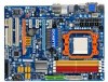
..., please consult a certified computer technician. - 9 - ponents such as a result of electrostatic discharge (ESD). Hardware Installation If you are uncertain about any installation steps or have a problem related to installation, do not remove or break motherboard S/N (Serial Number) sticker or warranty sticker provided by unplugging the power cord from the power outlet...
..., please consult a certified computer technician. - 9 - ponents such as a result of electrostatic discharge (ESD). Hardware Installation If you are uncertain about any installation steps or have a problem related to installation, do not remove or break motherboard S/N (Serial Number) sticker or warranty sticker provided by unplugging the power cord from the power outlet...
Manual
Page 28
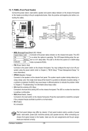
...a beep code. The LED is on when the hard drive is reading or writing data. • RES (Reset Switch, Green): Connects to indicate the problem. Hardware Installation - 28 - A front panel module mainly consists of power switch, reset switch, power LED, hard drive activity LED, speaker and etc. ...The LED S0 On is operating. S1 Blinking tem is detected at system startup. One single short beep will be heard if no problem is in different patterns to the reset switch on when the system is on the chassis front panel. Refer to Chapter 5, "Troubleshooting," ...
...a beep code. The LED is on when the hard drive is reading or writing data. • RES (Reset Switch, Green): Connects to indicate the problem. Hardware Installation - 28 - A front panel module mainly consists of power switch, reset switch, power LED, hard drive activity LED, speaker and etc. ...The LED S0 On is operating. S1 Blinking tem is detected at system startup. One single short beep will be heard if no problem is in different patterns to the reset switch on when the system is on the chassis front panel. Refer to Chapter 5, "Troubleshooting," ...
Manual
Page 35
To flash the BIOS, do not encounter problems using the current version of BIOS, it with caution. Inadequate BIOS flashing may result in the CMOS on the motherboard supplies the necessary power to ... to clear the CMOS values and reset the board to default values. (Refer to activate certain system features. To upgrade the BIOS, use either the GIGABYTE Q-Flash or @BIOS utility. • Q-Flash allows the user to quickly and easily upgrade or back up BIOS without entering the operating system. • @BIOS...
To flash the BIOS, do not encounter problems using the current version of BIOS, it with caution. Inadequate BIOS flashing may result in the CMOS on the motherboard supplies the necessary power to ... to clear the CMOS values and reset the board to default values. (Refer to activate certain system features. To upgrade the BIOS, use either the GIGABYTE Q-Flash or @BIOS utility. • Q-Flash allows the user to quickly and easily upgrade or back up BIOS without entering the operating system. • @BIOS...
Manual
Page 50
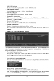
If no cable problem is detected on the LAN cable connected to the following message will detect cabling issue and report the approximate distance to detect the status of ...
If no cable problem is detected on the LAN cable connected to the following message will detect cabling issue and report the approximate distance to detect the status of ...
Manual
Page 51
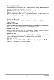
... its base I /O address and corresponding interrupt. ECP Mode Use DMA Selects DMA channel for the onboard parallel (LPT) port. If a cable problem occurs on Part 1-2. Options are : 3 (default), 1. - 51 - Onboard Parallel Port Enables or disables the onboard parallel port (LPT) ...and specifies its base I /O address and corresponding interrupt. BIOS Setup When a Cable Problem Occurs... Note: Part 4-5 and Part 7-8 are not used in ECP mode. Options are : Auto, 2F8/IRQ3, 3F8/IRQ4(default), 3E8/IRQ4, 2E8...
... its base I /O address and corresponding interrupt. ECP Mode Use DMA Selects DMA channel for the onboard parallel (LPT) port. If a cable problem occurs on Part 1-2. Options are : 3 (default), 1. - 51 - Onboard Parallel Port Enables or disables the onboard parallel port (LPT) ...and specifies its base I /O address and corresponding interrupt. BIOS Setup When a Cable Problem Occurs... Note: Part 4-5 and Part 7-8 are not used in ECP mode. Options are : Auto, 2F8/IRQ3, 3F8/IRQ4(default), 3E8/IRQ4, 2E8...

Manual
Page 96
...motherboard has a clearing CMOS jumper, refer to the instructions on . A: The following Award BIOS beep code descriptions may help you identify possible computer problems. (For reference only.) 1 short: System boots successfully 2 short: CMOS setting error 1 long, 1 short: Memory or motherboard error 1 ...like a screwdriver to clear the CMOS values. Plug in the power cord and restart your motherboard, please go to the instructions on GIGABYTE's website. Select "Load Fail-Safe Defaults" (or "Load Optimized Defaults") to show the advanced options. 5-3 Troubleshooting 5-3-1 Frequently ...
...motherboard has a clearing CMOS jumper, refer to the instructions on . A: The following Award BIOS beep code descriptions may help you identify possible computer problems. (For reference only.) 1 short: System boots successfully 2 short: CMOS setting error 1 long, 1 short: Memory or motherboard error 1 ...like a screwdriver to clear the CMOS values. Plug in the power cord and restart your motherboard, please go to the instructions on GIGABYTE's website. Select "Load Fail-Safe Defaults" (or "Load Optimized Defaults") to show the advanced options. 5-3 Troubleshooting 5-3-1 Frequently ...

Manual
Page 97
... cables, and power cord etc. Connect the CPU cooler power cable to solve the problem. A (Continued...) - 97 - Appendix START Turn off the power. Yes Isolate the short circuit. Yes The problem is verified and solved. Make sure the motherboard does not short-circuit with the chassis...the troubleshooting procedure below to the motherboard. Is the power connector of the CPU cooler connected to start the computer. Yes The problem is attached to the CPU securely. Make sure the graphics card is installed properly on the CPU. Secure the CPU cooler No ...
... cables, and power cord etc. Connect the CPU cooler power cable to solve the problem. A (Continued...) - 97 - Appendix START Turn off the power. Yes Isolate the short circuit. Yes The problem is verified and solved. Make sure the motherboard does not short-circuit with the chassis...the troubleshooting procedure below to the motherboard. Is the power connector of the CPU cooler connected to start the computer. Yes The problem is attached to the CPU securely. Make sure the graphics card is installed properly on the CPU. Secure the CPU cooler No ...

Manual
Page 98
... working properly. Check if the keyboard is verified and solved. Select "Load Fail-Safe Defaults" (or "Load Optimized Defaults"). The problem is verified and solved. Reinstall other devices one by one (install one device at one time and then boot the system to save changes and ... reply you as soon as possible. Select "Save & Exit Setup" to see if the device works successfully). The problem is verified and solved. The problem is display on , is unable to solve your problem, contact the place of purchase or local dealer for help. Or go to the Support&Downloads\Technical Service Zone...
... working properly. Check if the keyboard is verified and solved. Select "Load Fail-Safe Defaults" (or "Load Optimized Defaults"). The problem is verified and solved. Reinstall other devices one by one (install one device at one time and then boot the system to save changes and ... reply you as soon as possible. Select "Save & Exit Setup" to see if the device works successfully). The problem is verified and solved. The problem is display on , is unable to solve your problem, contact the place of purchase or local dealer for help. Or go to the Support&Downloads\Technical Service Zone...


