
Manual
Page 1
GA-MA785G-UD3H AM2+/AM2 socket motherboard for AMD Phenom™ II processor/ AMD Phenom™ processor/ AMD Athlon™ II processor/ AMD Athlon™ processor/ AMD Sempron™ processor User's Manual Rev. 1002 12ME-MA785U3-1002R
GA-MA785G-UD3H AM2+/AM2 socket motherboard for AMD Phenom™ II processor/ AMD Phenom™ processor/ AMD Athlon™ II processor/ AMD Athlon™ processor/ AMD Sempron™ processor User's Manual Rev. 1002 12ME-MA785U3-1002R
Manual
Page 3
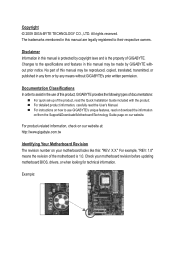
... features in any means without prior notice. Changes to assist in the use GIGABYTE's unique features, read the User's Manual. For instructions on how to their respective owners. Check your motherboard looks like this manual may be reproduced, copied, translated, transmitted, or published...manual is protected by any form or by copyright laws and is 1.0. No part of GIGABYTE. For product-related information, check on our website at: http://www.gigabyte.com.tw Identifying Your Motherboard Revision The revision number on our website. For example, "REV: 1.0" means the ...
... features in any means without prior notice. Changes to assist in the use GIGABYTE's unique features, read the User's Manual. For instructions on how to their respective owners. Check your motherboard looks like this manual may be reproduced, copied, translated, transmitted, or published...manual is protected by any form or by copyright laws and is 1.0. No part of GIGABYTE. For product-related information, check on our website at: http://www.gigabyte.com.tw Identifying Your Motherboard Revision The revision number on our website. For example, "REV: 1.0" means the ...
Manual
Page 4
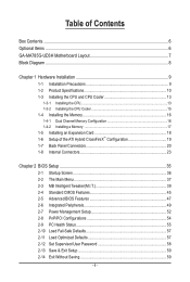
Table of Contents Box Contents...6 Optional Items...6 GA-MA785G-UD3H Motherboard Layout 7 Block Diagram...8 Chapter 1 Hardware Installation 9 1-1 Installation Precautions 9 1-2 Product Specifications 10 1-3 Installing the CPU and CPU Cooler 13 1-3-1 Installing the CPU 13 1-3-2 Installing the CPU ...
Table of Contents Box Contents...6 Optional Items...6 GA-MA785G-UD3H Motherboard Layout 7 Block Diagram...8 Chapter 1 Hardware Installation 9 1-1 Installation Precautions 9 1-2 Product Specifications 10 1-3 Installing the CPU and CPU Cooler 13 1-3-1 Installing the CPU 13 1-3-2 Installing the CPU ...

Manual
Page 6
Box Contents GA-MA785G-UD3H motherboard Motherboard driver disk User's Manual Quick Installation Guide One IDE cable Two SATA 3Gb/s cables I/O Shield • The box contents above are subject to change without notice. • The motherboard image is for reference only and the actual items shall depend on the product package you obtain. Optional Items Floppy disk...
Box Contents GA-MA785G-UD3H motherboard Motherboard driver disk User's Manual Quick Installation Guide One IDE cable Two SATA 3Gb/s cables I/O Shield • The box contents above are subject to change without notice. • The motherboard image is for reference only and the actual items shall depend on the product package you obtain. Optional Items Floppy disk...

Manual
Page 7
GA-MA785G-UD3H Motherboard Layout KB_USB VGA_DVI ATX_12V_2X4 HDMI OPTICAL USB_1394 USB_LAN CPU_FAN Socket AM2 PWR_FAN ATX AUDIO F_AUDIO PCIEX1_1 AMD 785G IT8718 F_USB1 F_USB2 F_USB3 DDR2_1 DDR2_2 DDR2_3 DDR2_4 SYS_FAN2 RTL8111C PCIEX16_1 IDE CD_IN PCIEX1_2 PCIEX1_3 CODEC PCIEX4_1 SPDIF_IO PCI1 PCI2 COM GA-MA785G-UD3H BATTERY CLR_CMOS AMD SB710 SATA2_1 SATA2_0 B_BIOS M_BIOS SATA2_5 SATA2_4 TSB43AB23 SATA2_3 SATA2_2 F_PANEL PWR_LED CI LPT SYS_FAN1 FDD F_1394_1 F_1394_2 - 7 -
GA-MA785G-UD3H Motherboard Layout KB_USB VGA_DVI ATX_12V_2X4 HDMI OPTICAL USB_1394 USB_LAN CPU_FAN Socket AM2 PWR_FAN ATX AUDIO F_AUDIO PCIEX1_1 AMD 785G IT8718 F_USB1 F_USB2 F_USB3 DDR2_1 DDR2_2 DDR2_3 DDR2_4 SYS_FAN2 RTL8111C PCIEX16_1 IDE CD_IN PCIEX1_2 PCIEX1_3 CODEC PCIEX4_1 SPDIF_IO PCI1 PCI2 COM GA-MA785G-UD3H BATTERY CLR_CMOS AMD SB710 SATA2_1 SATA2_0 B_BIOS M_BIOS SATA2_5 SATA2_4 TSB43AB23 SATA2_3 SATA2_2 F_PANEL PWR_LED CI LPT SYS_FAN1 FDD F_1394_1 F_1394_2 - 7 -
Manual
Page 9
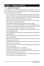
... an electrostatic shielding container. • Before unplugging the power supply cable from the power outlet before installing or removing the motherboard or other hardware components. • When connecting hardware components to the internal connectors on the computer power during the installation ... validation. • Always remove the AC power by your hardware components are connected tightly and securely. • When handling the motherboard, avoid touching any installation steps or have a problem related to the local voltage standard. • Before using the product, please...
... an electrostatic shielding container. • Before unplugging the power supply cable from the power outlet before installing or removing the motherboard or other hardware components. • When connecting hardware components to the internal connectors on the computer power during the installation ... validation. • Always remove the AC power by your hardware components are connected tightly and securely. • When handling the motherboard, avoid touching any installation steps or have a problem related to the local voltage standard. • Before using the product, please...
Manual
Page 12
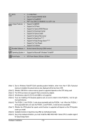
... 2) Whether 1066 MHz or above memory speed is supported depends on the CPU being used. (Note 3) The DVI-D port does not support D-Sub connection by motherboard model. (Note 9) Due to the hardware limitation, you must install the AMD AM3/ AM2+ Series CPU to install it in the PCIEX16_1 slot for Easy...
... 2) Whether 1066 MHz or above memory speed is supported depends on the CPU being used. (Note 3) The DVI-D port does not support D-Sub connection by motherboard model. (Note 9) Due to the hardware limitation, you must install the AMD AM3/ AM2+ Series CPU to install it in the PCIEX16_1 slot for Easy...
Manual
Page 13
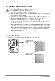
... on the surface of the CPU. • Do not turn on the computer if the CPU cooler is not recommended that the motherboard supports the CPU. (Go to GIGABYTE's website for the peripherals. The CPU cannot be set the frequency beyond hardware specifications since it does not meet the standard requirements for...
... on the surface of the CPU. • Do not turn on the computer if the CPU cooler is not recommended that the motherboard supports the CPU. (Go to GIGABYTE's website for the peripherals. The CPU cannot be set the frequency beyond hardware specifications since it does not meet the standard requirements for...
Manual
Page 14
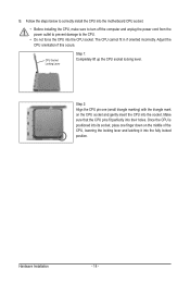
... middle of the CPU, lowering the locking lever and latching it into the socket. B. Follow the steps below to correctly install the CPU into the motherboard CPU socket. • Before installing the CPU, make sure to turn off the computer and unplug the power cord from the power outlet to prevent...
... middle of the CPU, lowering the locking lever and latching it into the socket. B. Follow the steps below to correctly install the CPU into the motherboard CPU socket. • Before installing the CPU, make sure to turn off the computer and unplug the power cord from the power outlet to prevent...
Manual
Page 15
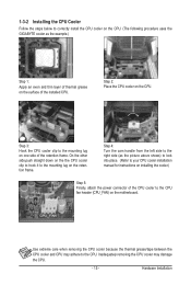
...retention frame. 1-3-2 Installing the CPU Cooler Follow the steps below to correctly install the CPU cooler on the CPU. (The following procedure uses the GIGABYTE cooler as the picture above shows) to lock into place. (Refer to your CPU cooler installation manual for instructions on installing the cooler.) Step ...5: Finally, attach the power connector of the CPU cooler to the CPU fan header (CPU_FAN) on the motherboard. Hardware Installation On the other side,push straight down on the the CPU cooler clip to hook it to the mounting lug on the CPU...
...retention frame. 1-3-2 Installing the CPU Cooler Follow the steps below to correctly install the CPU cooler on the CPU. (The following procedure uses the GIGABYTE cooler as the picture above shows) to lock into place. (Refer to your CPU cooler installation manual for instructions on installing the cooler.) Step ...5: Finally, attach the power connector of the CPU cooler to the CPU fan header (CPU_FAN) on the motherboard. Hardware Installation On the other side,push straight down on the the CPU cooler clip to hook it to the mounting lug on the CPU...
Manual
Page 16
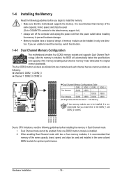
...mode. 1. It is recommended that you are unable to insert the memory, switch the direction. 1-4-1 Dual Channel Memory Configuration This motherboard provides four DDR2 memory sockets and supports Dual Channel Technology. When enabling Dual Channel mode with two or four memory modules, it is...in only one DDR2 memory module is installed, the BIOS will double the original memory bandwidth. The four DDR2 memory sockets are to GIGABYTE's website for optimum performance. DDR2_1 DDR2_2 DDR2_3 DDR2_4 Due to prevent hardware damage. • Memory modules have a foolproof design. ...
...mode. 1. It is recommended that you are unable to insert the memory, switch the direction. 1-4-1 Dual Channel Memory Configuration This motherboard provides four DDR2 memory sockets and supports Dual Channel Technology. When enabling Dual Channel mode with two or four memory modules, it is...in only one DDR2 memory module is installed, the BIOS will double the original memory bandwidth. The four DDR2 memory sockets are to GIGABYTE's website for optimum performance. DDR2_1 DDR2_2 DDR2_3 DDR2_4 Due to prevent hardware damage. • Memory modules have a foolproof design. ...

Manual
Page 17
..., make sure to turn off the computer and unplug the power cord from the power outlet to prevent damage to install DDR2 DIMMs on this motherboard. Notch DDR2 DIMM A DDR2 memory module has a notch, so it vertically into place when the memory module is securely inserted. - 17 - As indicated in the...
..., make sure to turn off the computer and unplug the power cord from the power outlet to prevent damage to install DDR2 DIMMs on this motherboard. Notch DDR2 DIMM A DDR2 memory module has a notch, so it vertically into place when the memory module is securely inserted. - 17 - As indicated in the...
Manual
Page 18
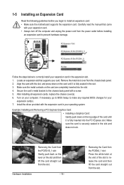
Remove the metal slot cover from the power outlet before you begin to install an expansion card: • Make sure the motherboard supports the expansion card. After installing all expansion cards, replace the chassis cover(s). 6. If necessary, go to BIOS Setup to make any required BIOS changes ...
Remove the metal slot cover from the power outlet before you begin to install an expansion card: • Make sure the motherboard supports the expansion card. After installing all expansion cards, replace the chassis cover(s). 6. If necessary, go to BIOS Setup to make any required BIOS changes ...
Manual
Page 19
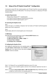
... ATI Hybrid CrossFireX system. Set Internal Graphics Mode to the ATI Catalyst™ Control Center. Configuring the Graphics Driver After installing the motherboard driver in the operating system, go to UMA. (Note 3) - C. Set UMA Frame Buffer Size to Disabled. - Connecting the... Graphics Cards Step 1: Observe the steps in - D. An ATI Hybrid CrossFireX-supported motherboard and correct driver - Set Surround View to 256MB or 512MB. (Note 3) - Select CrossFire™ on the Graphics menu on the PCI Express...
... ATI Hybrid CrossFireX system. Set Internal Graphics Mode to the ATI Catalyst™ Control Center. Configuring the Graphics Driver After installing the motherboard driver in the operating system, go to UMA. (Note 3) - C. Set UMA Frame Buffer Size to Disabled. - Connecting the... Graphics Cards Step 1: Observe the steps in - D. An ATI Hybrid CrossFireX-supported motherboard and correct driver - Set Surround View to 256MB or 512MB. (Note 3) - Select CrossFire™ on the Graphics menu on the PCI Express...
Manual
Page 21
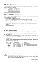
...to an external audio system that your device and then remove it from the connector. Do not rock it straight out from the motherboard. • When removing the cable, pull it side to side to the recommended system requirements (or better) below shows the ...the HD DVD or Blu-ray discs, refer to prevent an electrical short inside the cable connector. - 21 - A. Dual Display Configurations: This motherboard provides three ports for more information) • Playback software: CyberLink PowerDVD 8.0 or later (Note: Please ensure Hardware Acceleration is occurring • When...
...to an external audio system that your device and then remove it from the connector. Do not rock it straight out from the motherboard. • When removing the cable, pull it side to side to the recommended system requirements (or better) below shows the ...the HD DVD or Blu-ray discs, refer to prevent an electrical short inside the cable connector. - 21 - A. Dual Display Configurations: This motherboard provides three ports for more information) • Playback software: CyberLink PowerDVD 8.0 or later (Note: Please ensure Hardware Acceleration is occurring • When...

Manual
Page 23
... connectors you wish to connect. • Before installing the devices, be sure to the devices. • After installing the device and before turning on the motherboard. - 23 -
... connectors you wish to connect. • Before installing the devices, be sure to the devices. • After installing the device and before turning on the motherboard. - 23 -
Manual
Page 24
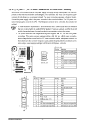
... power connector is not connected, the computer will not start. • To meet expansion requirements, it is turned off and all the components on the motherboard. Definition 1 GND (Only for 2x4-pin 12V) 2 GND (Only for 2x4-pin 12V) 3 GND 4 GND 5 +12V (Only for 2x4-pin 12V) 6 ... power supply providing a 2x4 12V and a 2x12 power connector, remove the protective covers from the 12V power connector and the main power connector on the motherboard. If a power supply is used (500W or greater). The power connector possesses a foolproof design. Connect the power supply cable to the CPU. When...
... power connector is not connected, the computer will not start. • To meet expansion requirements, it is turned off and all the components on the motherboard. Definition 1 GND (Only for 2x4-pin 12V) 2 GND (Only for 2x4-pin 12V) 3 GND 4 GND 5 +12V (Only for 2x4-pin 12V) 6 ... power supply providing a 2x4 12V and a 2x12 power connector, remove the protective covers from the 12V power connector and the main power connector on the motherboard. If a power supply is used (500W or greater). The power connector possesses a foolproof design. Connect the power supply cable to the CPU. When...
Manual
Page 25
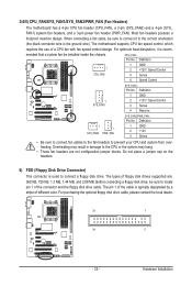
... from overheating. Definition 1 GND 2 +12V / Speed Control 3 Sense 4 Reserve 1 1 SYS_FAN2 PWR_FAN SYS_FAN2/PWR_FAN: Pin No. The motherboard supports CPU fan speed control, which requires the use of floppy disk drives supported are not configuration jumper blocks. Before connecting a floppy disk drive...the cable is the ground wire). The pin 1 of the connector and the floppy disk drive cable. 3/4/5) CPU_FAN/SYS_FAN1/SYS_FAN2/PWR_FAN (Fan Headers) The motherboard has a 4-pin CPU fan header (CPU_FAN), a 3-pin (SYS_FAN2) and a 4-pin (SYS_ FAN1) system fan headers, and a 3-pin power ...
... from overheating. Definition 1 GND 2 +12V / Speed Control 3 Sense 4 Reserve 1 1 SYS_FAN2 PWR_FAN SYS_FAN2/PWR_FAN: Pin No. The motherboard supports CPU fan speed control, which requires the use of floppy disk drives supported are not configuration jumper blocks. Before connecting a floppy disk drive...the cable is the ground wire). The pin 1 of the connector and the floppy disk drive cable. 3/4/5) CPU_FAN/SYS_FAN1/SYS_FAN2/PWR_FAN (Fan Headers) The motherboard has a 4-pin CPU fan header (CPU_FAN), a 3-pin (SYS_FAN2) and a 4-pin (SYS_ FAN1) system fan headers, and a 3-pin power ...

Manual
Page 29
... panel audio connections simultaneously. If your chassis provides an AC'97 front panel audio module, refer to the instructions on each wire instead of the motherboard header. Hardware Installation Make sure the wire assignments of the module connector match the pin assignments of a single plug. Definition 10 9 1 MIC2_L Pin No. For...
... panel audio connections simultaneously. If your chassis provides an AC'97 front panel audio module, refer to the instructions on each wire instead of the motherboard header. Hardware Installation Make sure the wire assignments of the module connector match the pin assignments of a single plug. Definition 10 9 1 MIC2_L Pin No. For...

Manual
Page 32
18) COM (Serial Port Header) The COM header can provide one serial port via an optional COM port cable. Definition 1 Signal 2 GND Hardware Installation - 32 - Pin No. For purchasing the optional COM port cable, please contact the local dealer. This function requires a chassis with chassis intrusion detection design. 1 Pin No. Definition 1 NDCD- 9 1 2 NSIN 10 2 3 NSOUT 4 NDTR- 5 GND 6 NDSR- 7 NRTS- 8 NCTS- 9 NRI- 10 No Pin 19) CI (Chassis Intrusion Header) This motherboard provides a chassis detection feature that detects if the chassis cover has been removed.
18) COM (Serial Port Header) The COM header can provide one serial port via an optional COM port cable. Definition 1 Signal 2 GND Hardware Installation - 32 - Pin No. For purchasing the optional COM port cable, please contact the local dealer. This function requires a chassis with chassis intrusion detection design. 1 Pin No. Definition 1 NDCD- 9 1 2 NSIN 10 2 3 NSOUT 4 NDTR- 5 GND 6 NDSR- 7 NRTS- 8 NCTS- 9 NRI- 10 No Pin 19) CI (Chassis Intrusion Header) This motherboard provides a chassis detection feature that detects if the chassis cover has been removed.


