Manual
Page 3
... Your Motherboard Revision The revision number on your motherboard revision before updating motherboard BIOS, drivers, or when looking for technical information. Copyright © 2009 GIGA-BYTE TECHNOLOGY CO., LTD. No part of GIGABYTE. For example, "REV: 1.0" means the revision of the motherboard is ...the information on/from the Support&Downloads\Motherboard\Technology Guide page on how to the specifications and features in the use GIGABYTE's unique features, read the User's Manual. Disclaimer Information in this manual is protected by any means without prior notice...
... Your Motherboard Revision The revision number on your motherboard revision before updating motherboard BIOS, drivers, or when looking for technical information. Copyright © 2009 GIGA-BYTE TECHNOLOGY CO., LTD. No part of GIGABYTE. For example, "REV: 1.0" means the revision of the motherboard is ...the information on/from the Support&Downloads\Motherboard\Technology Guide page on how to the specifications and features in the use GIGABYTE's unique features, read the User's Manual. Disclaimer Information in this manual is protected by any means without prior notice...
Manual
Page 4
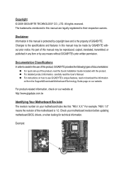
Table of Contents Box Contents...6 Optional Items...6 GA-MA785G-UD3H Motherboard Layout 7 Block Diagram...8 Chapter 1 Hardware Installation 9 1-1 Installation Precautions 9 1-2 Product Specifications 10 1-3 Installing the CPU and CPU Cooler ...CrossFireX™ Configuration 19 1-7 Back Panel Connectors 20 1-8 Internal Connectors 23 Chapter 2 BIOS Setup 35 2-1 Startup Screen 36 2-2 The Main Menu 37 2-3 MB Intelligent Tweaker(M.I.T 39 2-4 Standard CMOS Features 45 2-5 Advanced BIOS Features 47 2-6 Integrated Peripherals 49 2-7 Power Management Setup 52 2-8 PnP/PCI Configurations ...
Table of Contents Box Contents...6 Optional Items...6 GA-MA785G-UD3H Motherboard Layout 7 Block Diagram...8 Chapter 1 Hardware Installation 9 1-1 Installation Precautions 9 1-2 Product Specifications 10 1-3 Installing the CPU and CPU Cooler ...CrossFireX™ Configuration 19 1-7 Back Panel Connectors 20 1-8 Internal Connectors 23 Chapter 2 BIOS Setup 35 2-1 Startup Screen 36 2-2 The Main Menu 37 2-3 MB Intelligent Tweaker(M.I.T 39 2-4 Standard CMOS Features 45 2-5 Advanced BIOS Features 47 2-6 Integrated Peripherals 49 2-7 Power Management Setup 52 2-8 PnP/PCI Configurations ...

Manual
Page 5
... 62 3-3 Technical Manuals 62 3-4 Contact...63 3-5 System...63 3-6 Download Center 64 Chapter 4 Unique Features 65 4-1 Xpress Recovery2 65 4-2 BIOS Update Utilities 68 4-2-1 Updating the BIOS with the Q-Flash Utility 68 4-2-2 Updating the BIOS with the @BIOS Utility 71 4-3 EasyTune 6...72 4-4 Easy Energy Saver 73 4-5 Q-Share...75 4-6 Time Repair...76 Chapter 5 Appendix...77 5-1 Configuring SATA...
... 62 3-3 Technical Manuals 62 3-4 Contact...63 3-5 System...63 3-6 Download Center 64 Chapter 4 Unique Features 65 4-1 Xpress Recovery2 65 4-2 BIOS Update Utilities 68 4-2-1 Updating the BIOS with the Q-Flash Utility 68 4-2-2 Updating the BIOS with the @BIOS Utility 71 4-3 EasyTune 6...72 4-4 Easy Energy Saver 73 4-5 Q-Share...75 4-6 Time Repair...76 Chapter 5 Appendix...77 5-1 Configuring SATA...
Manual
Page 8
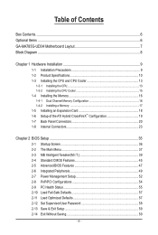
...) D-Sub DVI-D or HDMI (Note 1) 6 SATA 3Gb/s ATA-133/100/66/33 IDE Channel PCI Bus TSB43AB23 3 IEEE 1394a 12 USB Ports AMD SB710 Dual BIOS CODEC LPC Bus IT8718 Floppy LPT Port COM Port PS/2 KB or Mouse Surround Speaker Out Center/Subwoofer Speaker Out Side Speaker Out MIC Line...
...) D-Sub DVI-D or HDMI (Note 1) 6 SATA 3Gb/s ATA-133/100/66/33 IDE Channel PCI Bus TSB43AB23 3 IEEE 1394a 12 USB Ports AMD SB710 Dual BIOS CODEC LPC Bus IT8718 Floppy LPT Port COM Port PS/2 KB or Mouse Surround Speaker Out Center/Subwoofer Speaker Out Side Speaker Out MIC Line...
Manual
Page 12
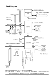
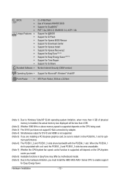
...supported will be less than 4 GB of licensed AWARD BIOS Support for DualBIOS™ PnP 1.0a, DMI 2.0, SM BIOS 2.4, ACPI 1.0b Support for @BIOS Support for Q-Flash Support for Xpress BIOS Rescue Support for Download Center Support for Xpress Install ... cooler you must install the AMD AM3/ AM2+ Series CPU to enable support for opti- When the PCIEX4_1 slot is populated with the PCIEX4_1 slot. BIOS w w w w Unique Features w w w w w w w w w w Bundled Software w 2 x 8 Mbit flash Use of physical memory is installed, ...
...supported will be less than 4 GB of licensed AWARD BIOS Support for DualBIOS™ PnP 1.0a, DMI 2.0, SM BIOS 2.4, ACPI 1.0b Support for @BIOS Support for Q-Flash Support for Xpress BIOS Rescue Support for Download Center Support for Xpress Install ... cooler you must install the AMD AM3/ AM2+ Series CPU to enable support for opti- When the PCIEX4_1 slot is populated with the PCIEX4_1 slot. BIOS w w w w Unique Features w w w w w w w w w w Bundled Software w 2 x 8 Mbit flash Use of physical memory is installed, ...
Manual
Page 16
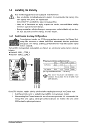
... - - - - - - - - 1-4 Installing the Memory Read the following guidelines before installing the memory in Dual Channel mode. 1. It is installed. 2. A memory module can be used . (Go to GIGABYTE's website for optimum performance. When enabling Dual Channel mode with two or four memory modules, it is installed, the...
... - - - - - - - - 1-4 Installing the Memory Read the following guidelines before installing the memory in Dual Channel mode. 1. It is installed. 2. A memory module can be used . (Go to GIGABYTE's website for optimum performance. When enabling Dual Channel mode with two or four memory modules, it is installed, the...
Manual
Page 18
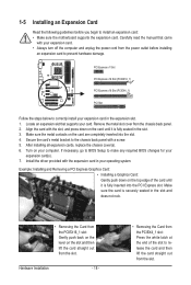
... steps below to the chassis back panel with the slot, and press down on the top edge of the slot to make any required BIOS changes for your card. After installing all expansion cards, replace the chassis cover(s). 6. Remove the metal slot cover from the slot. Align...the slot. 4. 1-5 Installing an Expansion Card Read the following guidelines before installing an expansion card to prevent hardware damage. If necessary, go to BIOS Setup to release the card and then lift the card straight out from the chassis back panel. 2. Example: Installing and Removing a PCI Express Graphics...
... steps below to the chassis back panel with the slot, and press down on the top edge of the slot to make any required BIOS changes for your card. After installing all expansion cards, replace the chassis cover(s). 6. Remove the metal slot cover from the slot. Align...the slot. 4. 1-5 Installing an Expansion Card Read the following guidelines before installing an expansion card to prevent hardware damage. If necessary, go to BIOS Setup to release the card and then lift the card straight out from the chassis back panel. 2. Example: Installing and Removing a PCI Express Graphics...
Manual
Page 19
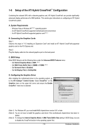
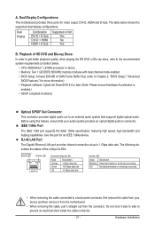
...for AMD platform. An ATI Hybrid CrossFireX-supported motherboard and correct driver - An ATI Hybrid CrossFireX-supported graphics card (Note 2) B. BIOS Setup Enter BIOS Setup to OnChipVGA. D. Configuring the Graphics Driver After installing the motherboard driver in the operating system first. - 19 - System Requirements...configuring an ATI Hybrid CrossFireX system. stalled. (Note 3) To change the Internal Graphics Mode or UMA Frame Buffer Size setting in BIOS Setup, be sure to disable the CrossFire function in the operating system, go to UMA. (Note 3) - Windows Vista or Windows...
...for AMD platform. An ATI Hybrid CrossFireX-supported motherboard and correct driver - An ATI Hybrid CrossFireX-supported graphics card (Note 2) B. BIOS Setup Enter BIOS Setup to OnChipVGA. D. Configuring the Graphics Driver After installing the motherboard driver in the operating system first. - 19 - System Requirements...configuring an ATI Hybrid CrossFireX system. stalled. (Note 3) To change the Internal Graphics Mode or UMA Frame Buffer Size setting in BIOS Setup, be sure to disable the CrossFire function in the operating system, go to UMA. (Note 3) - Windows Vista or Windows...
Manual
Page 21
...Athlon™ LE1640 processor or above • Memory: Two 1 GB DDR2 800 MHz memory modules with dual channel mode enabled • BIOS Setup: At least 256 MB of the LAN port LEDs. IEEE 1394a Port The IEEE 1394 port supports the IEEE 1394a specification, featuring...connector, first remove the cable from the connector. A. The following describes the states of UMA Frame Buffer Size (refer to Chapter 2, "BIOS Setup," "Advanced BIOS Features," for more information) • Playback software: CyberLink PowerDVD 8.0 or later (Note: Please ensure Hardware Acceleration is occurring • ...
...Athlon™ LE1640 processor or above • Memory: Two 1 GB DDR2 800 MHz memory modules with dual channel mode enabled • BIOS Setup: At least 256 MB of the LAN port LEDs. IEEE 1394a Port The IEEE 1394 port supports the IEEE 1394a specification, featuring...connector, first remove the cable from the connector. A. The following describes the states of UMA Frame Buffer Size (refer to Chapter 2, "BIOS Setup," "Advanced BIOS Features," for more information) • Playback software: CyberLink PowerDVD 8.0 or later (Note: Please ensure Hardware Acceleration is occurring • ...
Manual
Page 27
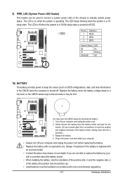
... power cord. 2. System Status LED S0 On S1 Blinking S3/S4/S5 Off 10) BATTERY The battery provides power to keep the values (such as BIOS configurations, date, and time information) in S3/S4 sleep state or powered off your computer. • Always turn off (S5). Turn off . You may be...
... power cord. 2. System Status LED S0 On S1 Blinking S3/S4/S5 Off 10) BATTERY The battery provides power to keep the values (such as BIOS configurations, date, and time information) in S3/S4 sleep state or powered off your computer. • Always turn off (S5). Turn off . You may be...
Manual
Page 28
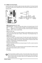
The LED keeps blinking when the sys- If a problem is detected, the BIOS may issue beeps in S3/S4 sleep S3/S4/S5 Off state or powered off (S5). • PW (Power Switch, Red): Connects to the power .... The LED is on when the hard drive is on the chassis front panel. When connecting your system using the power switch (refer to Chapter 2, "BIOS Setup," "Power Management Setup," for information about beep codes. • HD (Hard Drive Activity LED, Blue) Connects to the hard drive activity LED on the...
The LED keeps blinking when the sys- If a problem is detected, the BIOS may issue beeps in S3/S4 sleep S3/S4/S5 Off state or powered off (S5). • PW (Power Switch, Red): Connects to the power .... The LED is on when the hard drive is on the chassis front panel. When connecting your system using the power switch (refer to Chapter 2, "BIOS Setup," "Power Management Setup," for information about beep codes. • HD (Hard Drive Activity LED, Blue) Connects to the hard drive activity LED on the...
Manual
Page 33
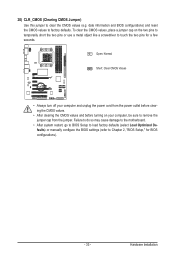
... to do so may cause damage to the motherboard. • After system restart, go to BIOS Setup to load factory defaults (select Load Optimized Defaults) or manually configure the BIOS settings (refer to Chapter 2, "BIOS Setup," for a few seconds. Open: Normal Short: Clear CMOS Values • Always turn ...off your computer, be sure to touch the two pins for BIOS configurations). - 33 - Hardware Installation To clear the CMOS values, place a jumper cap on your computer and unplug the power cord from the...
... to do so may cause damage to the motherboard. • After system restart, go to BIOS Setup to load factory defaults (select Load Optimized Defaults) or manually configure the BIOS settings (refer to Chapter 2, "BIOS Setup," for a few seconds. Open: Normal Short: Clear CMOS Values • Always turn ...off your computer, be sure to touch the two pins for BIOS configurations). - 33 - Hardware Installation To clear the CMOS values, place a jumper cap on your computer and unplug the power cord from the...
Manual
Page 35
... power to the CMOS to clear the CMOS values.) - 35 - To upgrade the BIOS, use either the GIGABYTE Q-Flash or @BIOS utility. • Q-Flash allows the user to quickly and easily upgrade or back up BIOS without entering the operating system. • @BIOS is turned off, the battery on using the current version of the...
... power to the CMOS to clear the CMOS values.) - 35 - To upgrade the BIOS, use either the GIGABYTE Q-Flash or @BIOS utility. • Q-Flash allows the user to quickly and easily upgrade or back up BIOS without entering the operating system. • @BIOS is turned off, the battery on using the current version of the...
Manual
Page 36
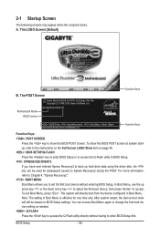
... instructions on the Full Screen LOGO Show item on page 48. : BIOS SETUP\Q-FLASH Press the key to enter BIOS Setup or to access the Q-Flash utility in Boot Menu is effective for subsequent access to accept. Motherboard Model BIOS Version GA-MA785G-UD3H E3 . . . . : BIOS Setup : XpressRecovery2 : Boot Menu : Qflash 06/05/2009-RS785-SB710-7A66BG04C...
... instructions on the Full Screen LOGO Show item on page 48. : BIOS SETUP\Q-FLASH Press the key to enter BIOS Setup or to access the Q-Flash utility in Boot Menu is effective for subsequent access to accept. Motherboard Model BIOS Version GA-MA785G-UD3H E3 . . . . : BIOS Setup : XpressRecovery2 : Boot Menu : Qflash 06/05/2009-RS785-SB710-7A66BG04C...
Manual
Page 37
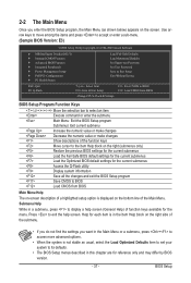
...Exit Without Saving ESC: Quit F8: Q-Flash Select Item F10: Save & Exit Setup Change CPU's Clock & Voltage F11: Save CMOS to BIOS F12: Load CMOS from BIOS BIOS Setup Program Function Keys Move the selection bar to select an item Execute command or enter the submenu Main Menu: Exit the... The on-screen description of a highlighted setup option is displayed on the bottom line of function keys available for reference only and may differ by BIOS version. - 37 - 2-2 The Main Menu Once you want in the Main Menu or a submenu, press + to access more advanced options. •...
...Exit Without Saving ESC: Quit F8: Q-Flash Select Item F10: Save & Exit Setup Change CPU's Clock & Voltage F11: Save CMOS to BIOS F12: Load CMOS from BIOS BIOS Setup Program Function Keys Move the selection bar to select an item Execute command or enter the submenu Main Menu: Exit the... The on-screen description of a highlighted setup option is displayed on the bottom line of function keys available for reference only and may differ by BIOS version. - 37 - 2-2 The Main Menu Once you want in the Main Menu or a submenu, press + to access more advanced options. •...
Manual
Page 38
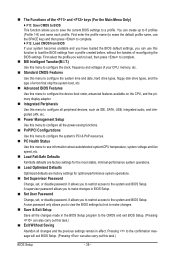
... time and date, hard drive types, floppy disk drive types, and the type of errors that stop the system boot, etc. Advanced BIOS Features Use this menu to configure the device boot order, advanced features available on the CPU, and the primary display adapter. Integrated Peripherals ...saving functions. PnP/PCI Configurations Use this menu to configure the system's PCI & PnP resources. PC Health Status Use this task.) BIOS Setup - 38 - You can also carry out this menu to make changes in effect. First select the profile you wish to load, then press to...
... time and date, hard drive types, floppy disk drive types, and the type of errors that stop the system boot, etc. Advanced BIOS Features Use this menu to configure the device boot order, advanced features available on the CPU, and the primary display adapter. Integrated Peripherals ...saving functions. PnP/PCI Configurations Use this menu to configure the system's PCI & PnP resources. PC Health Status Use this task.) BIOS Setup - 38 - You can also carry out this menu to make changes in effect. First select the profile you wish to load, then press to...
Manual
Page 39
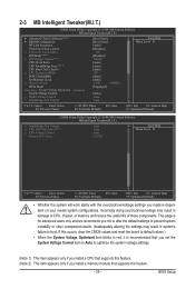
If this feature. - 39 - BIOS Setup Incorrectly doing overclock/overvoltage may result in damage to optimize the system voltage settings. (Note 1) This item appears only if you install a CPU that ...
If this feature. - 39 - BIOS Setup Incorrectly doing overclock/overvoltage may result in damage to optimize the system voltage settings. (Note 1) This item appears only if you install a CPU that ...
Manual
Page 40
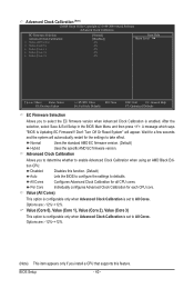
...is set to take effect. Normal Uses the standard AMD EC firmware version. (Default) Hybrid Uses the specific AMD EC firmware version. BIOS Setup - 40 - Advanced Clock Calibration (Note) CMOS Setup Utility-Copyright (C) 1984-2009 Award Software Advanced Clock Calibration EC Firmware Selection ...only when Advanced Clock Calibration is enabled. Options are : -12%~+12%. After the selection, select Save & Exit Setup in the BIOS Main Menu and then press . Per Core Individually configures Advanced Clock Calibration for all CPU cores. Wait for a few seconds and ...
...is set to take effect. Normal Uses the standard AMD EC firmware version. (Default) Hybrid Uses the specific AMD EC firmware version. BIOS Setup - 40 - Advanced Clock Calibration (Note) CMOS Setup Utility-Copyright (C) 1984-2009 Award Software Advanced Clock Calibration EC Firmware Selection ...only when Advanced Clock Calibration is enabled. Options are : -12%~+12%. After the selection, select Save & Exit Setup in the BIOS Main Menu and then press . Per Core Individually configures Advanced Clock Calibration for all CPU cores. Wait for a few seconds and ...
Manual
Page 41
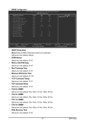
Row Precharge Time Options are : Auto (default), 3T~6T. BIOS Setup RAS to CAS R/W Delay Options are : Auto (default), 3T~6T. Trfc3 for DIMM4 Options are : Auto (default), 75ns, 105ns, 127.5ns, 195ns, 327.5ns. ...
Row Precharge Time Options are : Auto (default), 3T~6T. BIOS Setup RAS to CAS R/W Delay Options are : Auto (default), 3T~6T. Trfc3 for DIMM4 Options are : Auto (default), 75ns, 105ns, 127.5ns, 195ns, 327.5ns. ...
Manual
Page 42
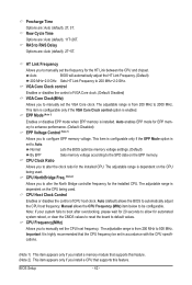
... EPP mode for automated system reboot, or clear the CMOS values to reset the board to configure EPP memory voltage. Normal Lets the BIOS optimize memory voltage settings. (Default) By EPP Sets memory voltage according to manually set the CPU host frequency. CPU NorthBridge Freq. (Note...2) This item appears only if you to manually set the VGA Core clock. Precharge Time Options are : Auto (default), 11T~26T. Auto BIOS will automatically adjust the HT Link Frequency. (Default) 200 MHz~2.0 GHz Sets HT Link Frequency to be set the frequency for the installed CPU...
... EPP mode for automated system reboot, or clear the CMOS values to reset the board to configure EPP memory voltage. Normal Lets the BIOS optimize memory voltage settings. (Default) By EPP Sets memory voltage according to manually set the CPU host frequency. CPU NorthBridge Freq. (Note...2) This item appears only if you to manually set the VGA Core clock. Precharge Time Options are : Auto (default), 11T~26T. Auto BIOS will automatically adjust the HT Link Frequency. (Default) 200 MHz~2.0 GHz Sets HT Link Frequency to be set the frequency for the installed CPU...


