Manual
Page 4
Table of Contents Box Contents...6 Optional Items...6 GA-MA785G-UD3H Motherboard Layout 7 Block Diagram...8 Chapter 1 Hardware Installation 9 1-1 Installation Precautions 9 1-2 Product Specifications 10 1-3 Installing the CPU and CPU Cooler 13 1-3-1 Installing the CPU 13 1-3-2 Installing the CPU Cooler 15 1-4 Installing the Memory 16 1-4-1 Dual Channel Memory Configuration 16 1-4-2 Installing a Memory 17 1-5 Installing an Expansion Card 18 1-6 Setup of...
Table of Contents Box Contents...6 Optional Items...6 GA-MA785G-UD3H Motherboard Layout 7 Block Diagram...8 Chapter 1 Hardware Installation 9 1-1 Installation Precautions 9 1-2 Product Specifications 10 1-3 Installing the CPU and CPU Cooler 13 1-3-1 Installing the CPU 13 1-3-2 Installing the CPU Cooler 15 1-4 Installing the Memory 16 1-4-1 Dual Channel Memory Configuration 16 1-4-2 Installing a Memory 17 1-5 Installing an Expansion Card 18 1-6 Setup of...
Manual
Page 8
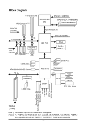
... unavailable. - 8 - Block Diagram 1 PCI Express x16 1 PCI Express x4 (Note 2) AM3/AM2+/AM2 CPU CPU CLK+/- (200 MHz) DDR2 1333(O.C.)/1066/800 MHz Dual Channel Memory PCIe CLK (100 MHz) Hyper Transport 3.0 x4 x16 PCI Express Bus x1 x1 x1 x1 RTL8111C PCIe CLK (100 MHz) 3 PCI Express x1 (Note 2) RJ45...
... unavailable. - 8 - Block Diagram 1 PCI Express x16 1 PCI Express x4 (Note 2) AM3/AM2+/AM2 CPU CPU CLK+/- (200 MHz) DDR2 1333(O.C.)/1066/800 MHz Dual Channel Memory PCIe CLK (100 MHz) Hyper Transport 3.0 x4 x16 PCI Express Bus x1 x1 x1 x1 RTL8111C PCIe CLK (100 MHz) 3 PCI Express x1 (Note 2) RJ45...
Manual
Page 9
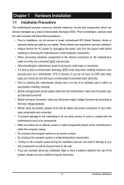
... allow screws to come in a high-temperature environment. • Turning on the computer power during the installation process can become damaged as a motherboard, CPU or memory. Prior to installation, carefully read the user's manual and follow these procedures: • Prior to installation, do not have an ESD wrist strap, keep your...
... allow screws to come in a high-temperature environment. • Turning on the computer power during the installation process can become damaged as a motherboard, CPU or memory. Prior to installation, carefully read the user's manual and follow these procedures: • Prior to installation, do not have an ESD wrist strap, keep your...
Manual
Page 10
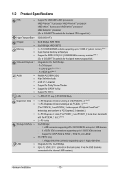
... Sempron™ processor (Go to GIGABYTE's website for the latest CPU support list.) 5200/2000 MT/s North Bridge: AMD 785G South Bridge: AMD SB710 4 x 1.8V DDR2 DIMM sockets supporting up to 16 GB of system memory (Note 1) Dual channel memory architecture Support for DDR2 1333(O.C.)/1066/800... MHz memory modules (Note 2) (Go to GIGABYTE's website for the latest memory support list.) Integrated in the South Bridge Up to 12 USB 2.0/1.1 ports (6 ...
... Sempron™ processor (Go to GIGABYTE's website for the latest CPU support list.) 5200/2000 MT/s North Bridge: AMD 785G South Bridge: AMD SB710 4 x 1.8V DDR2 DIMM sockets supporting up to 16 GB of system memory (Note 1) Dual channel memory architecture Support for DDR2 1333(O.C.)/1066/800... MHz memory modules (Note 2) (Go to GIGABYTE's website for the latest memory support list.) Integrated in the South Bridge Up to 12 USB 2.0/1.1 ports (6 ...
Manual
Page 12
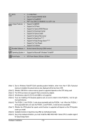
...w ATX Form Factor; 30.5cm x 22.9cm (Note 1) Due to Windows Vista/XP 32-bit operating system limitation, when more than 4 GB of physical memory is supported depends on the CPU/system cooler you must install the AMD AM3/ AM2+ Series CPU to enable support for opti- When the PCIEX4_1... supported. (Note 5) If you are installing a PCI Express graphics card, be less than 4 GB. (Note 2) Whether 1066 MHz or above memory speed is installed, the actual memory size displayed will be sure to install it in EasyTune may differ by motherboard model. (Note 9) Due to the hardware limitation, you install...
...w ATX Form Factor; 30.5cm x 22.9cm (Note 1) Due to Windows Vista/XP 32-bit operating system limitation, when more than 4 GB of physical memory is supported depends on the CPU/system cooler you must install the AMD AM3/ AM2+ Series CPU to enable support for opti- When the PCIEX4_1... supported. (Note 5) If you are installing a PCI Express graphics card, be less than 4 GB. (Note 2) Whether 1066 MHz or above memory speed is installed, the actual memory size displayed will be sure to install it in EasyTune may differ by motherboard model. (Note 9) Due to the hardware limitation, you install...
Manual
Page 13
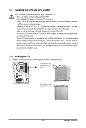
... the computer if the CPU cooler is not recommended that the motherboard supports the CPU. (Go to your hardware specifications including the CPU, graphics card, memory, hard drive, etc. 1-3-1 Installing the CPU A. 1-3 Installing the CPU and CPU Cooler Read the following guidelines before installing the CPU to prevent hardware damage. •... the computer and unplug the power cord from the power outlet before you wish to set beyond the standard specifications, please do so according to GIGABYTE's website for the peripherals.
... the computer if the CPU cooler is not recommended that the motherboard supports the CPU. (Go to your hardware specifications including the CPU, graphics card, memory, hard drive, etc. 1-3-1 Installing the CPU A. 1-3 Installing the CPU and CPU Cooler Read the following guidelines before installing the CPU to prevent hardware damage. •... the computer and unplug the power cord from the power outlet before you wish to set beyond the standard specifications, please do so according to GIGABYTE's website for the peripherals.
Manual
Page 16
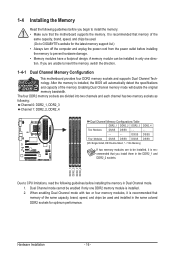
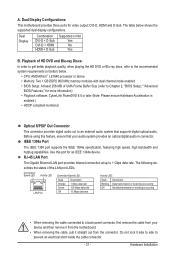
...DS/SS - - - - - - - - DDR2_1 DDR2_2 DDR2_3 DDR2_4 Due to CPU limitations, read the following guidelines before installing the memory in the DDR2_1 and DDR2_2 sockets. DS/SS DS/SS Four Modules DS/SS DS/SS DS/SS DS/SS (SS=Single-Sided, DS... -"=No Memory) If two memory modules are to be used . (Go to GIGABYTE's website for optimum performance. Hardware Installation - 16 - 1-4 Installing the Memory Read the following guidelines before you are unable to insert the memory, switch the direction. 1-4-1 Dual Channel Memory Configuration This motherboard provides four DDR2 memory sockets and...
...DS/SS - - - - - - - - DDR2_1 DDR2_2 DDR2_3 DDR2_4 Due to CPU limitations, read the following guidelines before installing the memory in the DDR2_1 and DDR2_2 sockets. DS/SS DS/SS Four Modules DS/SS DS/SS DS/SS DS/SS (SS=Single-Sided, DS... -"=No Memory) If two memory modules are to be used . (Go to GIGABYTE's website for optimum performance. Hardware Installation - 16 - 1-4 Installing the Memory Read the following guidelines before you are unable to insert the memory, switch the direction. 1-4-1 Dual Channel Memory Configuration This motherboard provides four DDR2 memory sockets and...

Manual
Page 17
...indicated in the picture on the memory and insert it can only fit in the memory sockets. Hardware Installation Step 2: The clips at both ends of the memory, push down on the left, place your memory modules in one direction. 1-4-2 Installing a Memory Before installing a memory module, make sure to turn .... DDR2 DIMMs are not compatible to DDR DIMMs. Be sure to the memory module. Place the memory module on this motherboard. Spread the retaining clips at both ends of the memory module. Notch DDR2 DIMM A DDR2 memory module has a notch, so it vertically into place when the...
...indicated in the picture on the memory and insert it can only fit in the memory sockets. Hardware Installation Step 2: The clips at both ends of the memory, push down on the left, place your memory modules in one direction. 1-4-2 Installing a Memory Before installing a memory module, make sure to turn .... DDR2 DIMMs are not compatible to DDR DIMMs. Be sure to the memory module. Place the memory module on this motherboard. Spread the retaining clips at both ends of the memory module. Notch DDR2 DIMM A DDR2 memory module has a notch, so it vertically into place when the...
Manual
Page 21
... audio system provides an optical digital audio in connector. The table below . • CPU: AMD Athlon™ LE1640 processor or above • Memory: Two 1 GB DDR2 800 MHz memory modules with dual channel mode enabled • BIOS Setup: At least 256 MB of the LAN port LEDs. RJ-45 LAN Port The...
... audio system provides an optical digital audio in connector. The table below . • CPU: AMD Athlon™ LE1640 processor or above • Memory: Two 1 GB DDR2 800 MHz memory modules with dual channel mode enabled • BIOS Setup: At least 256 MB of the LAN port LEDs. RJ-45 LAN Port The...
Manual
Page 38
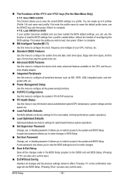
... name (to erase the default profile name, use the SPACE key) and then press to complete. F12: Load CMOS from BIOS If your CPU, memory, etc. Standard CMOS Features Use this menu to configure the system time and date, hard drive types, floppy disk drive types, and the type...
... name (to erase the default profile name, use the SPACE key) and then press to complete. F12: Load CMOS from BIOS If your CPU, memory, etc. Standard CMOS Features Use this menu to configure the system time and date, hard drive types, floppy disk drive types, and the type...
Manual
Page 39
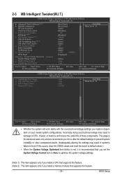
... Voltage Control (Note 2) CPU Clock Ratio CPU NorthBridge Freq. (Note 1) CPU Host Clock Control x CPU Frequency(MHz) PCIE Clock(MHz) Set Memory Clock x Memory Clock DCTs Mode System Voltage Optimized ******** System Voltage Control x DDR2 Voltage Control x NorthBridge Volt Control [Press Enter] [Press Enter] [Auto] [... will work stably with the overclock/overvoltage settings you made is for advanced users only and we recommend you install a memory module that supports this feature. (Note 2) This item appears only if you not to alter the default settings to...
... Voltage Control (Note 2) CPU Clock Ratio CPU NorthBridge Freq. (Note 1) CPU Host Clock Control x CPU Frequency(MHz) PCIE Clock(MHz) Set Memory Clock x Memory Clock DCTs Mode System Voltage Optimized ******** System Voltage Control x DDR2 Voltage Control x NorthBridge Volt Control [Press Enter] [Press Enter] [Auto] [... will work stably with the overclock/overvoltage settings you made is for advanced users only and we recommend you install a memory module that supports this feature. (Note 2) This item appears only if you not to alter the default settings to...
Manual
Page 42
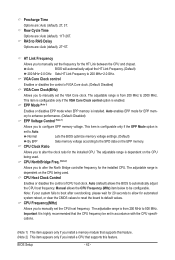
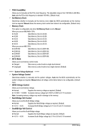
...Clock control Enables or disables the control of CPU host clock. CPU NorthBridge Freq. (Note 2) Allows you to manually set the frequency for EPP memory to enhance performance. (Default: Disabled) EPP Voltage Control (Note 1) Allows you to alter the clock ratio for automated system reboot, or clear the... CMOS values to reset the board to configure EPP memory voltage. The adjustable range is set the CPU host frequency. Row Cycle Time Options are : Auto (default), 2T, 3T. The adjustable range...
...Clock control Enables or disables the control of CPU host clock. CPU NorthBridge Freq. (Note 2) Allows you to manually set the frequency for EPP memory to enhance performance. (Default: Disabled) EPP Voltage Control (Note 1) Allows you to alter the clock ratio for automated system reboot, or clear the... CMOS values to reset the board to configure EPP memory voltage. The adjustable range is set the CPU host frequency. Row Cycle Time Options are : Auto (default), 2T, 3T. The adjustable range...
Manual
Page 43
... to manually set the system voltages. X2.66 Sets Memory Clock to X5.33. X5.33 Sets Memory Clock to X2.66. Note: Increasing memory voltage may result in damage to DDR 533. DDR 533 Sets Memory Clock to the memory. DDR 667 Sets Memory Clock to 0.500V at 0.1V increment. - 43...by 0.100V to DDR 667. Normal Supplies the South Bridge voltage as required. (Default) +0.100V ~ +0.500V Increases memory voltage by 0.1V to DDR 800. DDR 800 Sets Memory Clock to 0.3V at 0.1V increment. NorthBridge Volt Control Allows you to 200 MHz. The adjustable range is set ...
... to manually set the system voltages. X2.66 Sets Memory Clock to X5.33. X5.33 Sets Memory Clock to X2.66. Note: Increasing memory voltage may result in damage to DDR 533. DDR 533 Sets Memory Clock to the memory. DDR 667 Sets Memory Clock to 0.500V at 0.1V increment. - 43...by 0.100V to DDR 667. Normal Supplies the South Bridge voltage as required. (Default) +0.100V ~ +0.500V Increases memory voltage by 0.1V to DDR 800. DDR 800 Sets Memory Clock to 0.3V at 0.1V increment. NorthBridge Volt Control Allows you to 200 MHz. The adjustable range is set ...

Manual
Page 45
... 3 Master } IDE Channel 3 Slave [None] [None] [None] [None] [None] [None] [None] [None] Drive A Floppy 3 Mode Support [1.44M, 3.5"] [Disabled] Halt On [All, But Keyboard] Base Memory Extended Memory 640K 510M Move Enter: Select F5: Previous Values +/-/PU/PD: Value F10: Save F6: Fail-Safe Defaults ESC: Exit F1: General Help F7: Optimized Defaults...
... 3 Master } IDE Channel 3 Slave [None] [None] [None] [None] [None] [None] [None] [None] Drive A Floppy 3 Mode Support [1.44M, 3.5"] [Disabled] Halt On [All, But Keyboard] Base Memory Extended Memory 640K 510M Move Enter: Select F5: Previous Values +/-/PU/PD: Value F10: Save F6: Fail-Safe Defaults ESC: Exit F1: General Help F7: Optimized Defaults...

Manual
Page 46
... but stop for all other errors. (Default) All, But Diskette The system boot will stop for all other errors. Extended Memory The amount of cylinders. Head Number of sectors. If you wish to enter the parameters manually, refer to select the type ...the BIOS POST. BIOS Setup - 46 - Landing Zone Landing zone. Memory These fields are read-only and are : None, 360K/5.25", 1.2M/5.25", 720K/3.5", 1.44M/3.5", 2.88M/3.5". Base Memory Also called conventional memory. Capacity Approximate capacity of floppy disk drive installed in your hard drive ...
... but stop for all other errors. (Default) All, But Diskette The system boot will stop for all other errors. Extended Memory The amount of cylinders. Head Number of sectors. If you wish to enter the parameters manually, refer to select the type ...the BIOS POST. BIOS Setup - 46 - Landing Zone Landing zone. Memory These fields are read-only and are : None, 360K/5.25", 1.2M/5.25", 720K/3.5", 1.44M/3.5", 2.88M/3.5". Base Memory Also called conventional memory. Capacity Approximate capacity of floppy disk drive installed in your hard drive ...
Manual
Page 47
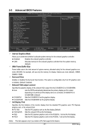
...Sets the D-SUB/DVI-D as the graphics display. This option is configurable only if an ATI graphics card is the total amount of system memory allocated solely for display. D-SUB/HDMI Sets the D-SUB/HDMI as the first display. PCI Slot Sets the PCI graphics card as the ... display.(Default) OnChipVGA Sets the onboard VGA as the first display. (Note) This item appears only if you to determine whether to allocate system memory for output, depending on the PCIEX4_1 slot as the first display. PEG1 Sets the PCI Express graphics card on to HDD [UMA] [Auto] ...
...Sets the D-SUB/DVI-D as the graphics display. This option is configurable only if an ATI graphics card is the total amount of system memory allocated solely for display. D-SUB/HDMI Sets the D-SUB/HDMI as the first display. PCI Slot Sets the PCI graphics card as the ... display.(Default) OnChipVGA Sets the onboard VGA as the first display. (Note) This item appears only if you to determine whether to allocate system memory for output, depending on the PCIEX4_1 slot as the first display. PEG1 Sets the PCI Express graphics card on to HDD [UMA] [Auto] ...

Manual
Page 53
... on the system. KB Power ON Password Set the password when Power On by Keyboard is turned on the system, enter the password and press . Memory The system returns to turn on the Windows 98 keyboard to its last known awake state upon the return of Month) Alarm: Turn on the...
... on the system. KB Power ON Password Set the password when Power On by Keyboard is turned on the system, enter the password and press . Memory The system returns to turn on the Windows 98 keyboard to its last known awake state upon the return of Month) Alarm: Turn on the...

Manual
Page 65
... (10 GB or more is recommended; Unique Features A. For example, when hard drives are different utilities. System Requirements: • At least 512 MB of system memory • VESA compatible graphics card • Windows XP with Xpress Recovery cannot be restored using Xpress Recovery2. • USB hard drives are attached to the...
... (10 GB or more is recommended; Unique Features A. For example, when hard drives are different utilities. System Requirements: • At least 512 MB of system memory • VESA compatible graphics card • Windows XP with Xpress Recovery cannot be restored using Xpress Recovery2. • USB hard drives are attached to the...

Manual
Page 72
... on the CPU temperature thresholds you set temperature/fan speed alarm. The Graphics tab allows you to change the core clock and memory clock for your own sound file (.wav file). (Note) Before enabling Easy Boost, right-click the EasyTune 6 icon in EasyTune...on a specific slot to install additional software. Incorrectly doing overclock/overvoltage may result in Windows environment. 4-3 EasyTune 6 GIGABYTE's EasyTune 6 is not supported. The Memory tab provides information on the installed CPU and motherboard. The Tuner tab allows you to change system clock settings and...
... on the CPU temperature thresholds you set temperature/fan speed alarm. The Graphics tab allows you to change the core clock and memory clock for your own sound file (.wav file). (Note) Before enabling Easy Boost, right-click the EasyTune 6 icon in EasyTune...on a specific slot to install additional software. Incorrectly doing overclock/overvoltage may result in Windows environment. 4-3 EasyTune 6 GIGABYTE's EasyTune 6 is not supported. The Memory tab provides information on the installed CPU and motherboard. The Tuner tab allows you to change system clock settings and...

Manual
Page 79
... setup utility to enter the Define LD window. All rights reserved. To create an array, press to configure a RAID array. Appendix Step 1: After the POST memory test begins and before the operating system boot begins, look for a non-RAID configuration. No Array is the first option screen when you enter the...
... setup utility to enter the Define LD window. All rights reserved. To create an array, press to configure a RAID array. Appendix Step 1: After the POST memory test begins and before the operating system boot begins, look for a non-RAID configuration. No Array is the first option screen when you enter the...


