
Manual
Page 7
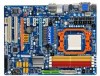
GA-MA785G-UD3H Motherboard Layout KB_USB VGA_DVI ATX_12V_2X4 HDMI OPTICAL USB_1394 USB_LAN CPU_FAN Socket AM2 PWR_FAN ATX AUDIO F_AUDIO PCIEX1_1 AMD 785G IT8718 F_USB1 F_USB2 F_USB3 DDR2_1 DDR2_2 DDR2_3 DDR2_4 SYS_FAN2 RTL8111C PCIEX16_1 IDE CD_IN PCIEX1_2 PCIEX1_3 CODEC PCIEX4_1 SPDIF_IO PCI1 PCI2 COM GA-MA785G-UD3H BATTERY CLR_CMOS AMD SB710 SATA2_1 SATA2_0 B_BIOS M_BIOS SATA2_5 SATA2_4 TSB43AB23 SATA2_3 SATA2_2 F_PANEL PWR_LED CI LPT SYS_FAN1 FDD F_1394_1 F_1394_2 - 7 -
GA-MA785G-UD3H Motherboard Layout KB_USB VGA_DVI ATX_12V_2X4 HDMI OPTICAL USB_1394 USB_LAN CPU_FAN Socket AM2 PWR_FAN ATX AUDIO F_AUDIO PCIEX1_1 AMD 785G IT8718 F_USB1 F_USB2 F_USB3 DDR2_1 DDR2_2 DDR2_3 DDR2_4 SYS_FAN2 RTL8111C PCIEX16_1 IDE CD_IN PCIEX1_2 PCIEX1_3 CODEC PCIEX4_1 SPDIF_IO PCI1 PCI2 COM GA-MA785G-UD3H BATTERY CLR_CMOS AMD SB710 SATA2_1 SATA2_0 B_BIOS M_BIOS SATA2_5 SATA2_4 TSB43AB23 SATA2_3 SATA2_2 F_PANEL PWR_LED CI LPT SYS_FAN1 FDD F_1394_1 F_1394_2 - 7 -
Manual
Page 12
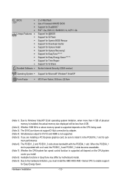
... HDMI is installed, the actual memory size displayed will depend on the CPU being used. (Note 3) The DVI-D port does not support D-Sub connection by motherboard model. (Note 9) Due to the hardware limitation, you must install the AMD AM3/ AM2+ Series CPU to Windows Vista/XP 32-bit operating system limitation... (Note 9) Support for Time Repair Support for Q-Share Norton Internet Security (OEM version) Operating System w Support for Microsoft® Windows® Vista/XP Form Factor w ATX Form Factor; 30.5cm x 22.9cm (Note 1) Due to enable support for opti-
... HDMI is installed, the actual memory size displayed will depend on the CPU being used. (Note 3) The DVI-D port does not support D-Sub connection by motherboard model. (Note 9) Due to the hardware limitation, you must install the AMD AM3/ AM2+ Series CPU to Windows Vista/XP 32-bit operating system limitation... (Note 9) Support for Time Repair Support for Q-Share Norton Internet Security (OEM version) Operating System w Support for Microsoft® Windows® Vista/XP Form Factor w ATX Form Factor; 30.5cm x 22.9cm (Note 1) Due to enable support for opti-

Manual
Page 23
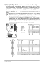
... 20 18 1) ATX_12V_2X4 2) ATX 3) CPU_FAN 4) SYS_FAN1/SYS_FAN2 5) PWR_FAN 6) FDD 7) IDE 8) SATA2_0/1/2/3/4/5 9) PWR_LED 10) BATTERY 7 8 11 9 4 6 16 19 17 11) F_PANEL 12) F_AUDIO 13) CD_IN 14) SPDIF_IO 15) F_USB1/F_USB2 16) F_1394_1/F_1394_2 17) LPT 18) COM 19) CI 20) CLR_CMOS Read the following guidelines before turning on the motherboard. - 23 - Hardware Installation...
... 20 18 1) ATX_12V_2X4 2) ATX 3) CPU_FAN 4) SYS_FAN1/SYS_FAN2 5) PWR_FAN 6) FDD 7) IDE 8) SATA2_0/1/2/3/4/5 9) PWR_LED 10) BATTERY 7 8 11 9 4 6 16 19 17 11) F_PANEL 12) F_AUDIO 13) CD_IN 14) SPDIF_IO 15) F_USB1/F_USB2 16) F_1394_1/F_1394_2 17) LPT 18) COM 19) CI 20) CLR_CMOS Read the following guidelines before turning on the motherboard. - 23 - Hardware Installation...
Manual
Page 24
...GND (Only for 2x4-pin 12V) 3 GND 4 GND 5 +12V (Only for 2x4-pin 12V) 6 +12V (Only for 2x4-pin 12V) 7 +12V 8 +12V 12 24 1 13 ATX ATX: Pin No. 1 2 3 4 5 6 7 8 9 10 11 12 Definition Pin No. 3.3V 13 3.3V 14 GND 15 +5V 16 GND 17 +5V 18 GND 19 Power Good 20...power supply providing a 2x4 12V and a 2x12 power connector, remove the protective covers from the 12V power connector and the main power connector on the motherboard. The power connector possesses a foolproof design. Connect the power supply cable to the CPU. If the 12V power connector is not connected, the computer ...
...GND (Only for 2x4-pin 12V) 3 GND 4 GND 5 +12V (Only for 2x4-pin 12V) 6 +12V (Only for 2x4-pin 12V) 7 +12V 8 +12V 12 24 1 13 ATX ATX: Pin No. 1 2 3 4 5 6 7 8 9 10 11 12 Definition Pin No. 3.3V 13 3.3V 14 GND 15 +5V 16 GND 17 +5V 18 GND 19 Power Good 20...power supply providing a 2x4 12V and a 2x12 power connector, remove the protective covers from the 12V power connector and the main power connector on the motherboard. The power connector possesses a foolproof design. Connect the power supply cable to the CPU. If the 12V power connector is not connected, the computer ...

Manual
Page 97
... to the CPU_FAN header properly? No Correctly insert the memory into the memory socket. Is the power connector of the CPU cooler connected to the motherboard. 5-3-2 Troubleshooting Procedure If you encounter any troubles during system startup, follow the troubleshooting procedure below to solve the problem. A (Continued...) - 97 - Insert the graphics card... problem is securely seated in the expansion slot and power connectors are firmly attached. Yes The problem is attached to start the computer. Connect the ATX main power cable and the 12V power cable.
... to the CPU_FAN header properly? No Correctly insert the memory into the memory socket. Is the power connector of the CPU cooler connected to the motherboard. 5-3-2 Troubleshooting Procedure If you encounter any troubles during system startup, follow the troubleshooting procedure below to solve the problem. A (Continued...) - 97 - Insert the graphics card... problem is securely seated in the expansion slot and power connectors are firmly attached. Yes The problem is attached to start the computer. Connect the ATX main power cable and the 12V power cable.


